Week 9 - Project 1 - Door Trim Lower with Engineering Features
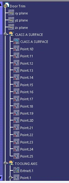
Creation of Tooling Axis:
1. Check the qualty of surface by using the boundary command.
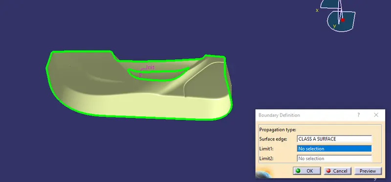
2. Select in which direction we can see the whole surface.
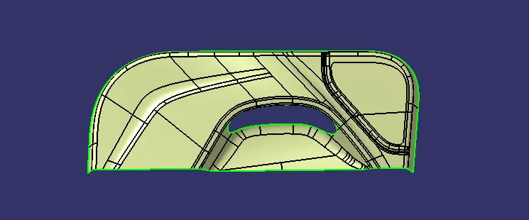
3. Extract the surface and place the point on the center of the surface.

4. Create point on the center.
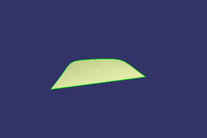
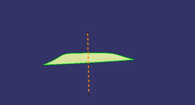
5. Create a line perpendicular to the surface and thats our tooling axis and make it thicker and brighter to make it visible.
Draft Analysis on Class-A:
1. Change the surface to the material mode.
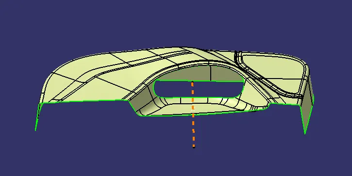
2. To start the draft analysis first we have to place the compass on the tooling axis. For that zoom out and find the compass where it is.
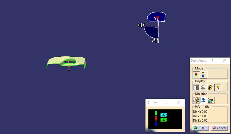
3. Click and drag the compass on the tooling axis and then lock it on the axis.
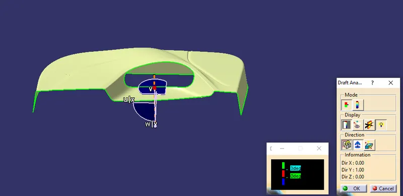
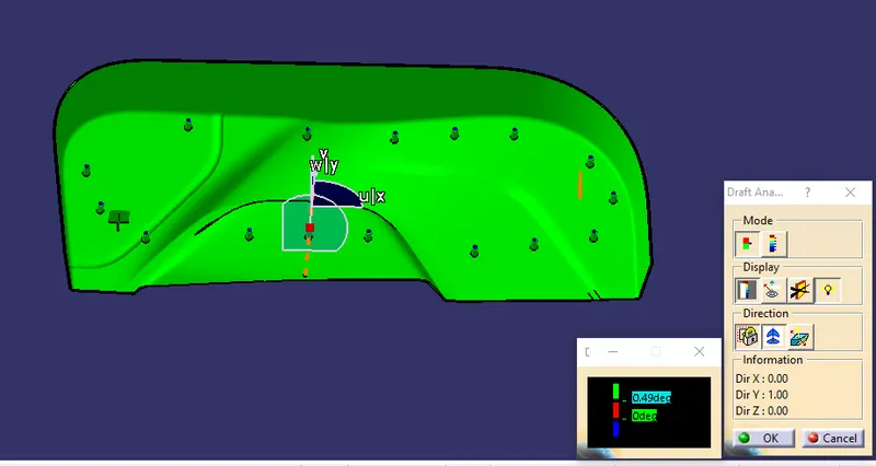
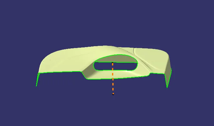
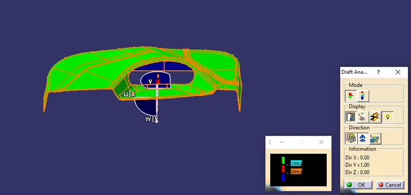
4. Click on the surface anywhere to start draft analysis. Here GREEN color shows the surface is more than 3 degree.
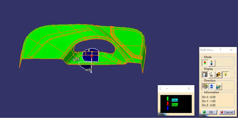
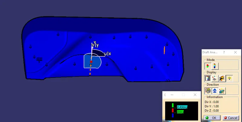
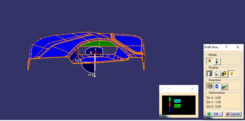
5. Click on invert draft surface to check the surface further more.
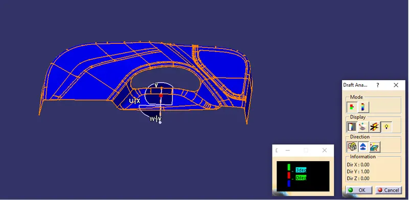
Multi-Section View of Draft Analysis:
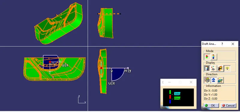
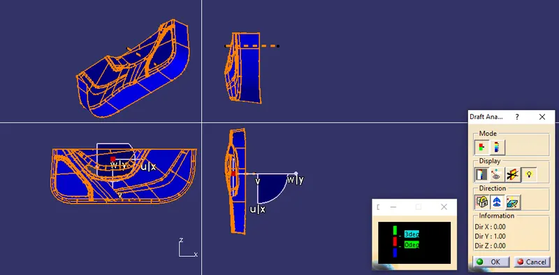
Multi-Section View of Plastic Component:
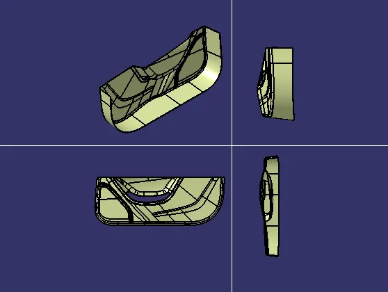
Multi-Section View of Solid Component:
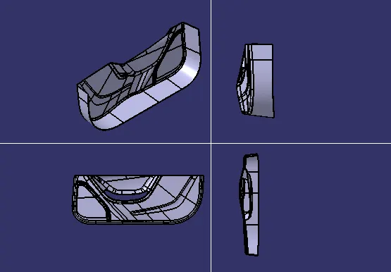
Multi-Section View of Solid Component After Fixing the Heat Stakes & Locators:
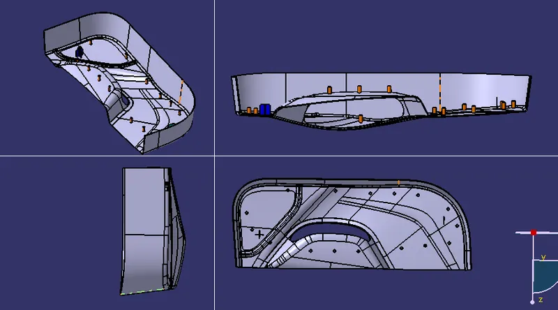
Sketches with Iso-Constrained Status:
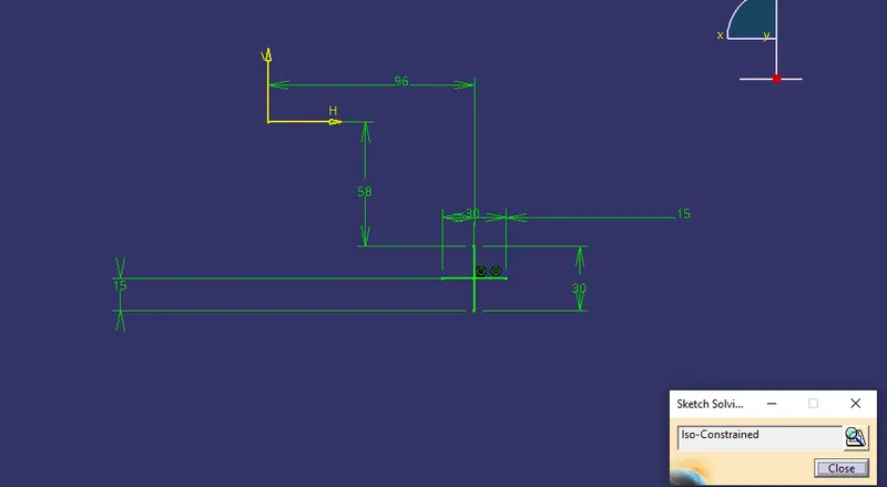
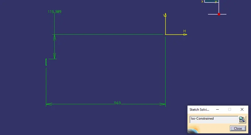
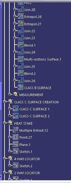
Heat Stakes:

4-Way Locator:
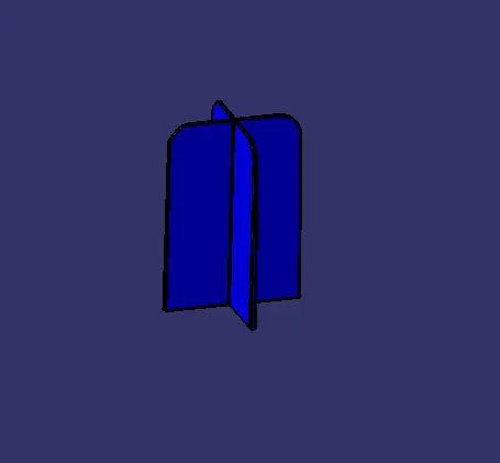
2-Way Locator:

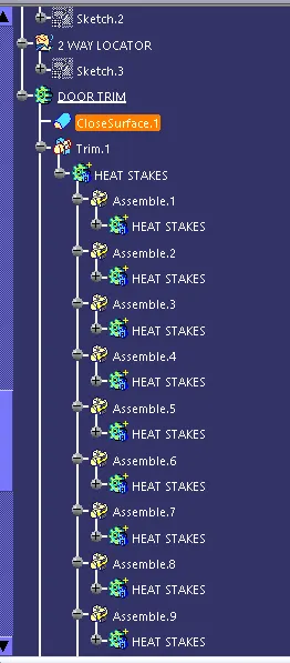
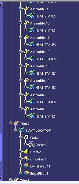
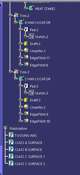
Draft Analysis on Plastic Component:
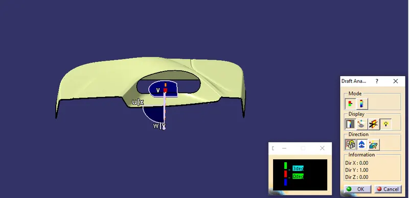
Draft Analysis on Final Component: