Door Trim Lower with Engineering Features
ENGINEERING FEATURES CREATION
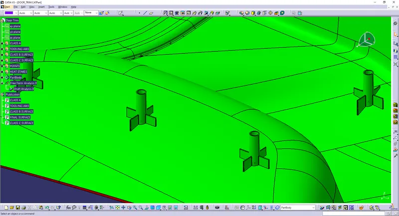
OBJECTIVE: Create Heat stakes for the door trim considering design rules using Class A surface with the thickness of the component 2.5 mm.
INTRODUCTION:
3-2-1 PRINCIPLE:
The 3-2-1 method is a work-holding principle where three pins are located on the 1st principle plane, i.e., either XY, YZ, ZX. And two pins are located on the 2nd plane perpendicular to the 1st plane, and at last, one pin on the plane is mutually perpendicular to the 1st and 2nd planes.
A work-piece free in space can move in an infinite number of directions. For analysis, this motion can be broken down into 12 directional movements or "degrees of freedom". All 12 degrees of freedom must be restricted to ensure proper referencing of a work-piece.
As shown in image below, the 12 degrees of freedom all relate to the central axis of the work-piece. Notice the 6 axial degrees and 6 radial degrees of freedom. The axial degrees of freedom permit straight-line movement in both directions along the 3-principle axis shown as X, Y & Z. The radial degrees of freedom permit rotational movement, in both clockwise & counter clockwise radial directions around the same three axes.
Degrees of Freedom of a Rigid Body
Consider the rigid body shown below which is situated in space. It can have 12 degrees of freedom.

HEAT STAKES :
Heat Staking is a pulsed-heat process to join two or more parts out of which one at least is made of plastic. The process is to deform the plastic material using heat and force at a set process time. The bond is made by partially de-forming the plastic part in order to fix the other. Heat Staking makes it easy to bond metal to plastic and is commonly used in high volume/low cost applications such as automotive, IT and consumer appliances.
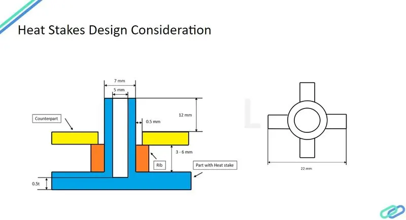
Shaping Plastic Using Heat and Pressure:
The plastic is deformed by heating it to a temperature above the glass transition temperature. Super-heated air or a thermode is used for this. Pressure is then applied to create the stake. After the stake has been formed, the plastic should be cooled down again below the glass transition temperature. Cooling is performed under constant pressure to ensure good fixation of the parts. Compressed air can be applied for cooling when a thermode is used. Heat is used to facilitate the creation of the stake. Heat control is critical, especially for glass-filled plastics which often have a process window of less than 10 degrees Celsius. When the temperature is too high, the glass fibres come out of the plastic which leads to a rough surface and adhesion to the thermode. If the temperature is too low, the plastic will crack due to cold deformation.
Heat staking Benefits:
- Similar and dissimilar materials may be joined: metal to metal, plastic to plastic, metal to plastic
- Accurate control operating within a small process window
- Local heating resulting in no damage to surrounding materials
- Processing of glass-filled materials
- No mechanical vibration
- Many heat-stake shapes possible through custom designed tools
2-WAY LOCATORS:
A 2-way locating pin restricts motion along 1 axis (or 2 degrees of Freedom), like a round pin in a slot. Likewise, a 4-way pin restricts 4 degrees of freedom along 2 axes. A round locating pin located concentrically in a hole is a common application of a 4-way pin, and helps to further secure the piece.
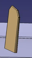
4-WAY LOCATORS:
4-way mean you prevent movement at 2 axes (+X, -X, +Y and -Y) on the plane. Generally, you have cylindrical pin on the fixture and circular hole at workpiece part.
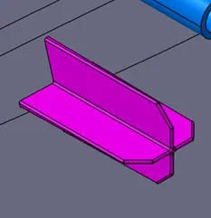
TOOLING AXIS:
- Considering the Ejection from the cavity of the mould after manufacturing the interior trim must have the nominal 3-degree draft angle.
- Hence the tooling axis is created by considering the above factor.
- The direction in which the mold or core and cavity opens is the tooling axis.
- In this case below is the tooling axis that I have used.
- The Line in the black color is our tooling axis.

CLASS A SURFACE:
- In automotive design, a class A surface is any of a set of freeform surfaces of high efficiency and quality.
- It is the visible aesthetic surface of any automotive component.
- Class A surface refers to those surfaces which are visible and abide to the physical meaning, in a product.
- This classification is primarily used in the automotive and increasingly in consumer goods industry.
- It is a requirement where aesthetics has a significant contribution.
- For this reason, the exterior of automobiles is deemed Class-A.
- Below is the CLASS SURFACE that I have used for this model.
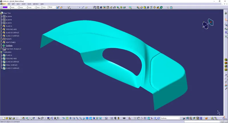
CLASS B SURFACE:
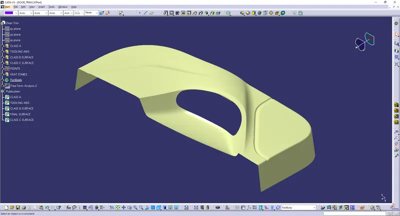
- Class B surfaces are Engineering Surfaces which are invisible to the eyes or often on the back side of the Class A surfaces.
- It is mainly the thickness of the component or Class A.
- These surfaces need to be designed as per the Class A surface i.e., the continuity, thickness of the component, functionality etc should be maintained.
- These surfaces include the main engineering features such as Screw bosses, Ribs, Snaps, Stiffeners and fixations.
- B surfaces also do not contain any aesthetic styling content and textures since it is not visible to eyes.
- Below is the image of CLASS B that I have created.
CLASS C SURFACE:
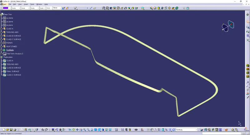
- Class C surfaces are connectors between Class A and B surfaces.
- This surface connects both A and B surfaces along the Tooling Axis.
- It contains the draft as per the design.
- It is basically the thickened surface between both A and B surface.
- Below is the Class C surface that I have created for this model.
CLOSED SURFACE:
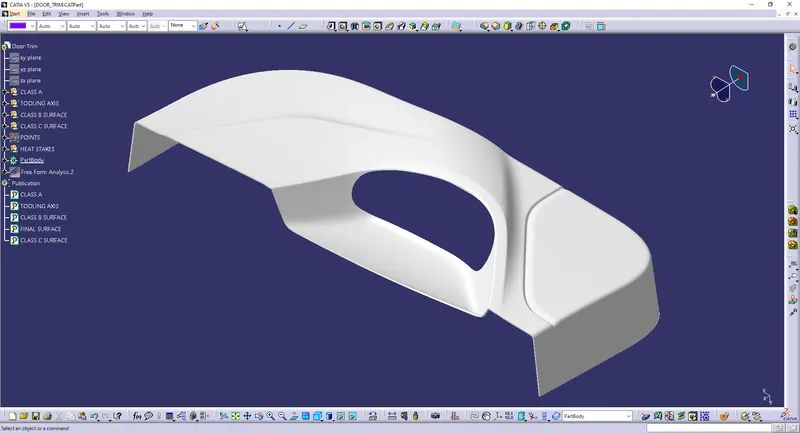
- Now the class – A and Class- C surfaces were joined together by removing the gaps in-between them with the help of extrapolation and Trim surface.
- Then, by defining the part body by using the Closed Surface command in Part Design, the component's solid body is created.
DRAFT ANALYSIS:
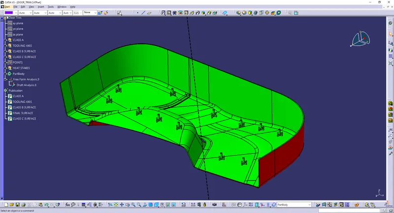
- Draft Analysis is a tool in CATIA which identifies the zones which deviates from the specified values of angles along a defined draft direction using colour codes.
- It highlights the regions of draft using colours.
- Draft analysis is the first step performed after receiving the Class A of the component.
- Draft analysis should be passed in order to make the plastic component manufacturable.
- Acceptable draft angles are used as range for draft analysis that is 0 to 3 degree.
- For Heat Stakes draft given is 0.5 to 2 degree.
SOLID BODY:
CONCLUSION:
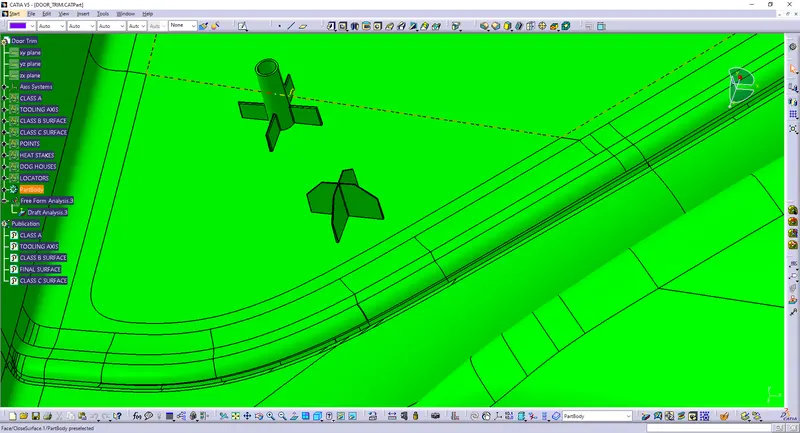
This reports concludes the creation of HEAT STAKES , DOG HOUSES & LOCATORS by following all Design Consideration for this model.