Bumper Design
BUMPER DESIGN
OBJECTIVE:
Create the Bumper Plastic component through the given Class-A surface. To begin with, the tooling axis for the given Class-A Surface should be created meeting the requirements of the draft angle and at the end perform the Draft analysis on the model.
INTRODUCTION :
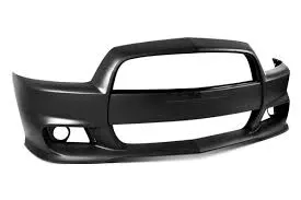
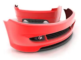
A bumper is a structure attached to or integrated with the front and rear ends of a motor vehicle, to absorb impact in a minor collision, ideally minimizing repair costs.
They are designed to absorb impact to the front and rear of vehicles and minimize low-speed collision damage. Today, standard passenger vehicle bumpers have a rigid reinforcing bar under the outer cover, with sections of compressible foam or plastic underneath.
A bumper is made up of four parts:
- Bumper cover.
- The bumper absorber.
- The bumper reinforcement bar.
- The bumper mounting system
Modern bumpers are made with a combination of materials. The first element is an impact absorbing spring device, usually gas-filled cartridges which mount the front bumper to the chassis. This allows the bumper system to absorb minor impacts without any damage.
Actually, bumpers in cars are meant for absorbing shock or impact at low velocity like accidentally hitting while reversing the car.
Now coming to the selection of material for making bumper, the material should have the capability to absorb the impact (i.e.) either nullify the effect or reduce the effect of the strike.
Lets consider metals as bumpers, metals transfer the load applied at one end to the other with negligible loss, so metals are not optimum material for bumpers. Lets consider plastics as bumpers, they have tendency to absorb load and reduce the effect of the impact also rubbers have the tendency to absorb and almost nullify the effect.
Looking into design and processing aspect, bumpers are big in size so they are processed by techniques like injection molding, blow molding and roto-molding. Considering the above processing techniques plastics are suitable material of choice.
Considering the above said processing methods, most commonly ABS, PC/ABS is injection molded and blow molded ABS are used in cars like Hyundai, Ford. When processed by roto-molding pulverized HDPE is processed easily and is used in making bumpers.
Acrylonitrile Butadiene Styrene(ABS):
Acrylonitrile Butadiene Styrene is a copolymer made by polymerizing styrene and acrylonitrile in the presence of polybutadiene. The styrene gives the plastic a shiny, impervious surface. The butadiene, a rubbery substance, provides resilience even at low temperatures. A variety of modifications can be made to improve impact resistance, toughness, and heat resistance.
PROPERTIES OF ABS-
| PROPERTY | METRIC | UNITS | ENGLISH | UNITS |
|---|---|---|---|---|
| General | ||||
| Density | 1.01e3 - 1.21e3 | kg/m^3 | 63.1 - 75.5 | lb/ft^3 |
| Mechanical | ||||
| Yield Strength | 1.85e7 - 5.1e7 | Pa | 2.68 - 7.4 | ksi |
| Tensile Strength | 2.76e7 - 5.52e7 | Pa | 4 - 8.01 | ksi |
| Elongation | 0.015 - 1 | % strain | 1.5 - 100 | % strain |
| Hardness (Vickers) | 5.49e7 - 1.5e8 | Pa | 5.6 - 15.3 | HV |
| Fracture Toughness | 1.19e6 - 4.29e6 | Pa/m^0.5 | 1.08 - 3.9 | ksi/in^0.5 |
| Young's Modulus | 1.19e9 - 2.9e9 | Pa | 0.16 - 0.421 | 10^6 psi |
DESIGN FLOW:
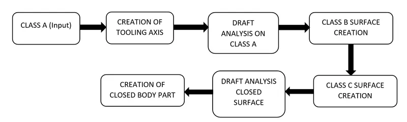
TOOLING AXIS:
- Considering the Ejection from the cavity of the mould after manufacturing the interior trim must have the nominal 3-degree draft angle.
- Hence the tooling axis is created by considering the above factor.
- The direction in which the mold or core and cavity opens is the tooling axis.
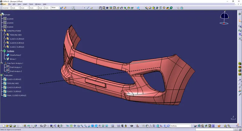
- In this case below is the tooling axis that I have used.
- The Line in the black color is our tooling axis
CLASS A SURFACE:
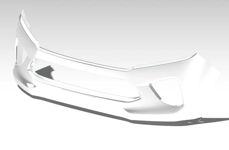
- In automotive design, a class A surface is any of a set of freeform surfaces of high efficiency and quality.
- It is the visible aesthetic surface of any automotive component.
- Class A surface refers to those surfaces which are visible and abide to the physical meaning, in a product.
- This classification is primarily used in the automotive and increasingly in consumer goods industry.
- It is a requirement where aesthetics has a significant contribution.
- For this reason, the exterior of automobiles is deemed Class-A.
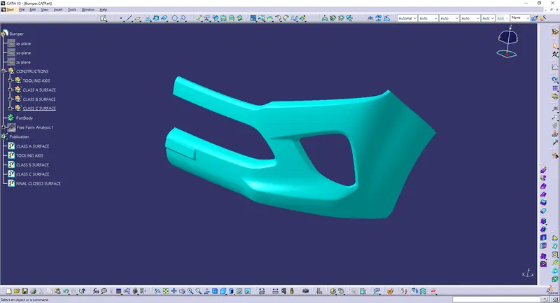
- Below is the CLASS SURFACE that is given to me as input.
CLASS B SURFACE:
- Class B surfaces are Engineering Surfaces which are invisible to the eyes or often on the back side of the Class A surfaces.
- It is mainly the thickness of the component or Class A.
- These surfaces need to be designed as per the Class A surface i.e., the continuity, thickness of the component, functionality etc should be maintained.
- These surfaces include the main engineering features such as Screw bosses, Ribs, Snaps, Stiffeners and fixations.
- B surfaces also do not contain any aesthetic styling content and textures since it is not visible to eyes.
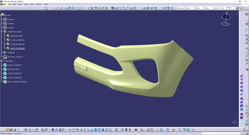
- Below is the image of CLASS B that I have created
CLASS C SURFACE:
- Class C surfaces are connectors between Class A and B surfaces.
- This surface connects both A and B surfaces along the Tooling Axis.
- It contains the draft as per the design.
- It is basically the thickened surface between both A and B surface.
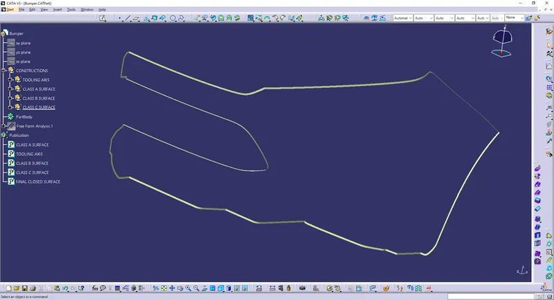
- Below is the Class C surface that I have created for this model
CLOSED SURFACE:
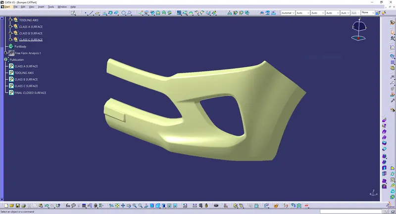
- Now the class – A and Class- C surfaces were joined together by removing the gaps in-between them with the help of extrapolation and Trim surface.
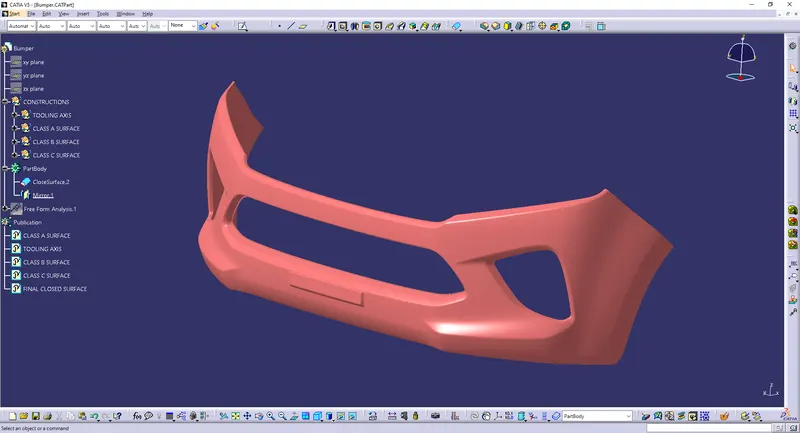
- Then, by defining the part body by using the Closed Surface command in Part Design, the component's solid body is created.
FINAL SOLID BODY:
DRAFT ANALYSIS:
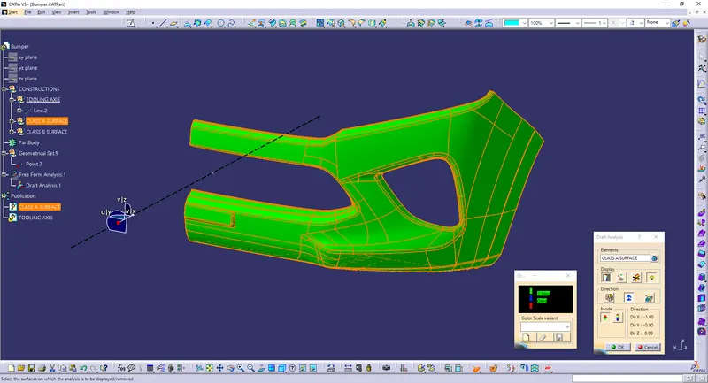
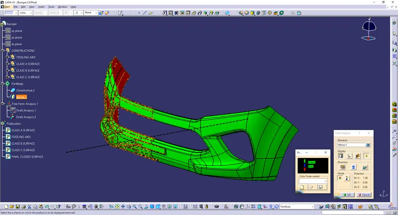
- Draft Analysis is a tool in CATIA which identifies the zones which deviates from the specified values of angles along a defined draft direction using colour codes.
- It highlights the regions of draft using colours.
- Draft analysis is the first step performed after receiving the Class A of the component.
- Draft analysis should be passed in order to make the plastic component manufacturable.
- Acceptable draft angles are used as range for draft analysis that is 0 to 3 degree.
SURFACE:
SOILD BODY:
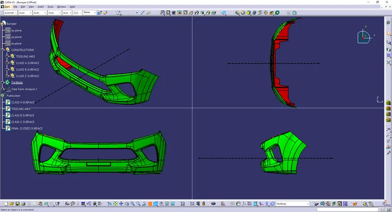
FOUR VIEWS:
CONCLUSION-
Finally the Class – A, B & C surfaces with the Tooling Direction have been Published and the bumper is moved on to the designing of the next operation – the creation of other features.