Coin Holder Design
COIN HOLDER DESIGN
OBJECTIVE:
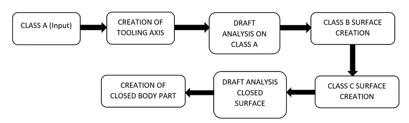
To create the coin holder plastic component through the CLASS A surface and create the required tooling axis and perform the Draft analysis on the model so that our end product is manufacturable.
INTRODUCTION:
The Coin Holder is used in automobiles for storage of coin and other small items which needs to easily accessible for the passengers.The Location of the holder might be in the Dashboard,side door trims and between the car seats.
The design should be in a such a way that the it should blend in with other components and interior and should not take more space.Also, it should be comfortable for easy access.This report explains the process of coin holder design which is created based on the A-surface input recieved.
DESIGN CONSIDERATION:
- Class – A surface should be aesthetically smooth and good.
- Final Solid should also pass the draft analysis.
- Plastics used in cars have the potential to develop new properties to meet the rapidly changing needs of the automotive industry.
- Material used for this product is
Polypropylene
Polypropylrne is used the most frequently of any plastic in automotive manufacturing. Being a thermoplastic polymer, it can easily be formed into almost any shape. It has excellent chemical and heat resistance and is generally resistant to impact. Given this plastic's resume, you will frequently find it in car bumpers, gas cans and even the carpet fibers of your car's interior flooring. It's also a more economical alternative to expensive plastics of similar strength and durability, which helps drive down the cost of manufacturing.
| Homopol | Copolym | ||
| Density | / kgm-3 | 905 | 905 |
| Price / Tonne | / £ | 680 | 620 |
| Tensile Strength | / Mpa | 33 | 25 |
| Tensile Modulus | / Gpa | 1.4 | 1.0 |
| Elongation at Break | / % | 150 | 300 |
| Hardness | / Rockwell "R" Scale | 90 | 80 |
| Notched Izod Impact | / kJm-1 | 0.07 | 0.1 |
| Heat Distortion Temp (HDT) | @ 0.45 MPa / °C | 105 | 100 |
| Heat Distortion Temp (HDT) | @ 1.80 MPa / °C | 65 | 60 |
| Volume Resistivity | / logÙm | 19 | 19 |
| Oxygen Index | / % | 17 | 17 |
P.P Is the material having good surface finish , Translucent & Good fatigue resistance taking all these under consideration we choose this material.
TOOLING AXIS:
- Considering the Ejection from the cavity of the mould after manufacturing the interior trim must have the nominal 3-degree draft angle.
- Hence the tooling axis is created by considering the above factor.
- The direction in which the mold or core and cavity opens is the tooling axis.
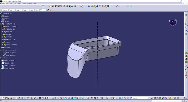
- In this case below is the tooling axis that I have used.
- The Line in the black color is our tooling axis.
CLASS A SURFACE:
- In automotive design, a class A surface is any of a set of freeform surfaces of high efficiency and quality.
- It is the visible aesthetic surface of any automotive component.
- Class A surface refers to those surfaces which are visible and abide to the physical meaning, in a product.
- This classification is primarily used in the automotive and increasingly in consumer goods industry.
- It is a requirement where aesthetics has a significant contribution.
- For this reason, the exterior of automobiles is deemed Class-A.
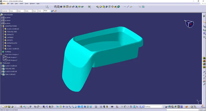
- Below is the CLASS SURFACE that I have used .
CLASS B SURFACE:
- Class B surfaces are Engineering Surfaces which are invisible to the eyes or often on the back side of the Class A surfaces.
- It is mainly the thickness of the component or Class A.
- These surfaces need to be designed as per the Class A surface i.e., the continuity, thickness of the component, functionality etc should be maintained.
- These surfaces include the main engineering features such as Screw bosses, Ribs, Snaps, Stiffeners and fixations.
- B surfaces also do not contain any aesthetic styling content and textures since it is not visible to eyes.
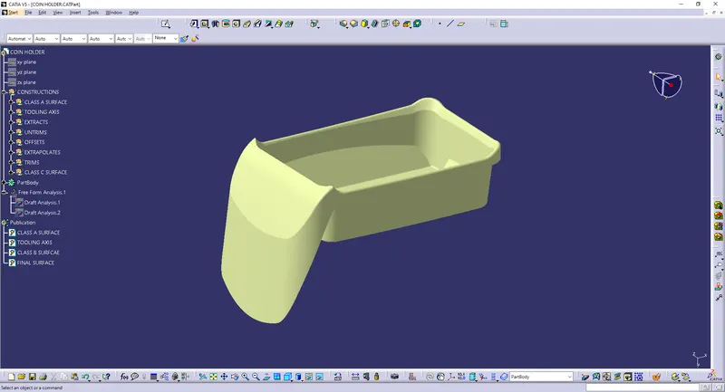
- Below is the image of CLASS B that I have created.
CLASS C SURFACE:
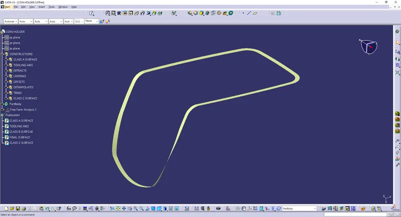
- Class C surfaces are connectors between Class A and B surfaces.
- This surface connects both A and B surfaces along the Tooling Axis.
- It contains the draft as per the design.
- It is basically the thickened surface between both A and B surface.
- Below is the Class C surface that I have used for this model.
CLOSED SURFACE:
- Now the class – A and Class- C surfaces were joined together by removing the gaps in-between them with the help of extrapolation(tangent continuity) and Trim surface.
- Then, by defining the part body by using the Closed Surface command in Part Design, the component's solid body is created.
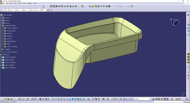
Final Solid body after using CLOSED BODY command in PART Workbench :
DRAFT ANALYSIS:
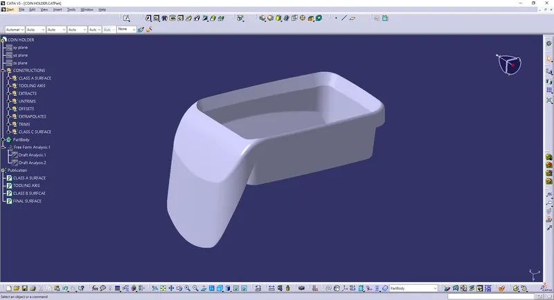
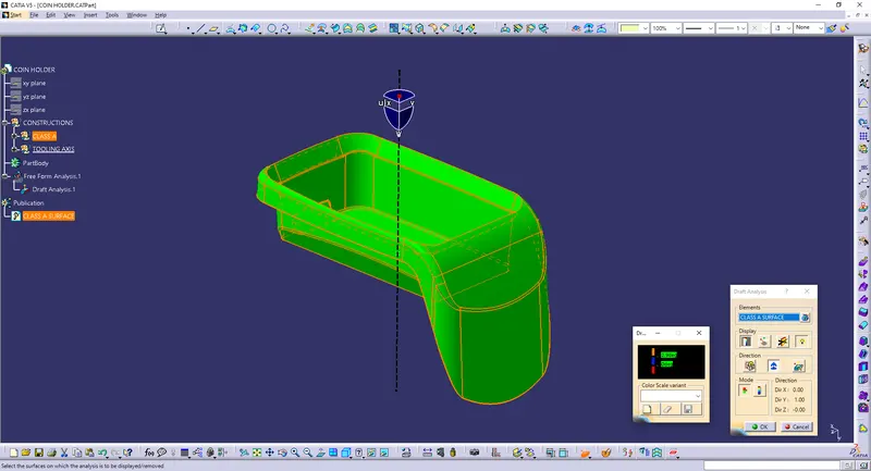
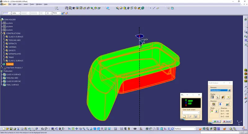
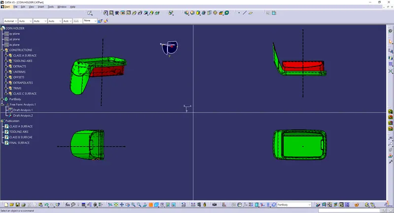
- Draft Analysis is a tool in CATIA which identifies the zones which deviates from the specified values of angles along a defined draft direction using colour codes.
- It highlights the regions of draft using colours.
- Draft analysis is the first step performed after receiving the Class A of the component.
- Draft analysis should be passed in order to make the plastic component manufacturable.
- Acceptable draft angles are used as range for draft analysis.
- Below are the images of draft analysis that i have performed for this model
DRAFT ANALYSIS ON CLASS A SURFACE :
DRAFT ANALYSIS ON SOLID BODY :
FOUR VIEWS :
CONCLUSION
Finally the Class – A, B & C surfaces with the Tooling Direction have been Published and the Coin Holder is moved on to the designing of the next operation – the creation of other features.