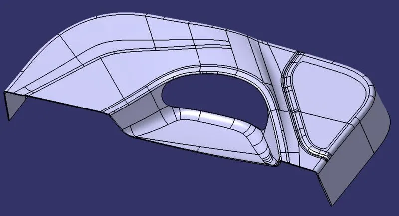
Week 9 - Project 1 - Door Trim Lower with Engineering Features
Object :- Create the Door Trim Lower Plastic component through the given Class-A surface. To begin with, the tooling axis for the given Class-A Surface should be created meeting the requirements of the draft angle and at the end perform the Draft analysis on the model.
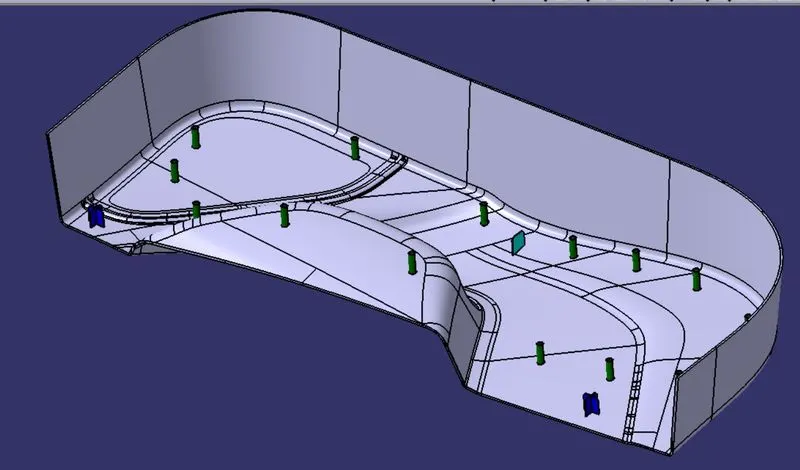
And create the Heat Stakes and the locators considering the design rules for the door applique.
Introduction :- This project is done on CATIA software. This software is different from other. It is easy to designing for surface modelling. Its have more accuracy than other.
Class A Surface :-
In automotive design application Class A Surfaces are created on all visible exterior surfaces (ex; body panels, bumper, grill, lights etc.) and all visible surfaces of see-touch & feel parts in interior (ex: Dashboard, seats, door pads etc.). This can also include beauty covers in the engine compartment, mud flaps, trunk panels and carpeting. This surface has 0 mm thickness.
Given Class A Surface
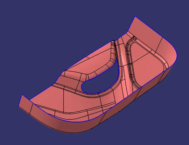
Tooling Axis :-
Tooling axis or tooling direction is main consideration for plastic part and mold parts because it defines movement of mold part and possibility of plastic part to come-out from mold part (Core and Cavity). In Molding machine arrangement is given to open the mold along a direction which is known as Tooling Direction. The mold is built from two separate halves (Core and Cavity) and tooling direction basically define the direction of mold pulls apart. Tooling direction is known as primary direction.
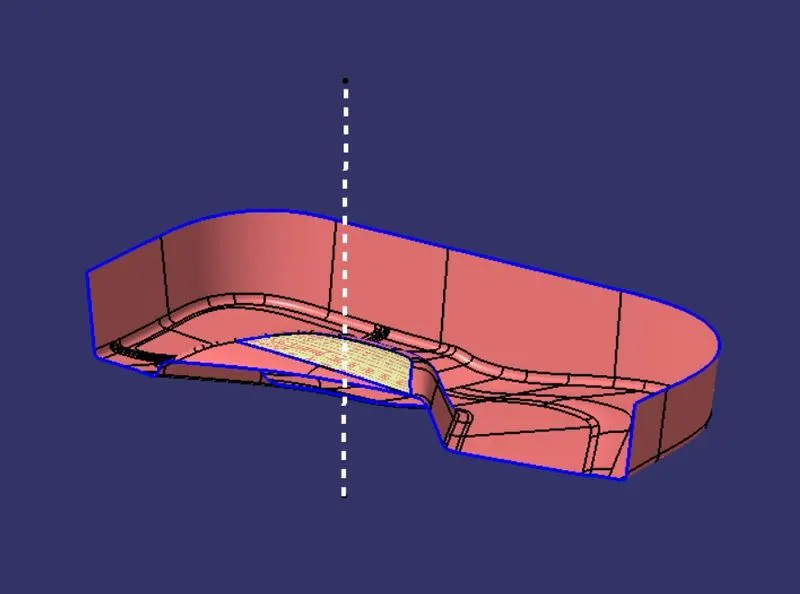
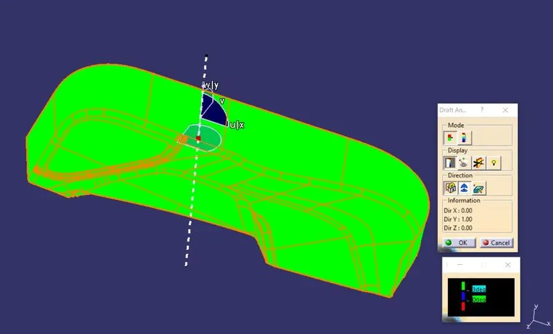
- Here I create a tooling axis. First I extract a surface then create a mid pont on this surface. After then I create a vertical line through this point and anlyze the draft analysis, then I found every thing is ok. So finally I consider it as tooling axis.
Another Method of Creating Tooling Axis :-
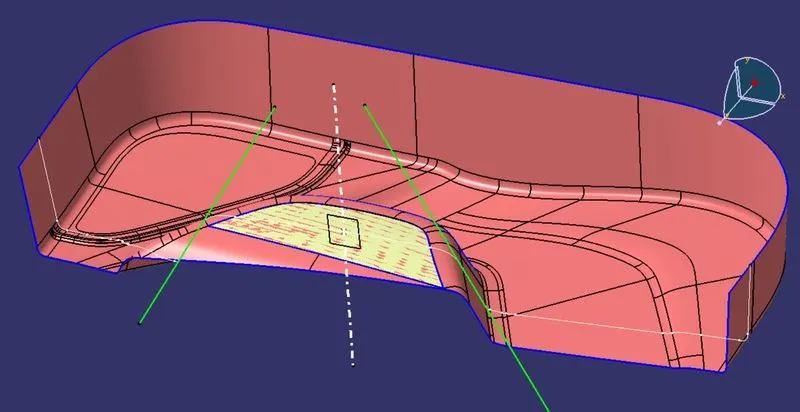
- Here I create a tooling axis. First I extract a surface then create a mid ponit on this surface then create a plane at this point. After it I create a intersection curve whith the help of class a surface and plane. According to myself thinking analysis I create 2 lines (green lines) along this taper surface. And then I create a bisecting line with the help of 2 green lines and then anlyze the draft analysis, after it I found that everything is ok. So finally it is considered as tooling axis. You can see according to below figure.
Draft Analysis :-
The Draft Analysis allows the user to easily analyze a part for proper draft angle. A Draft Angle describes the amount of taper for molded or cast parts perpendicular to the parting line. Draft Analysis is applicable for 3D part models. To create a draft analysis for any 3D part file, the user needs to select part/surface and select the pull direction. You can change the pull direction.
Draft Analysis of Class A Surface In CATIA :- It provides colour based identification. With the help of this we can easily find that which surface is in clear and which is in stuck by colour changing. Here I give the draft angle 3 degree. The result in colour based that the surface which green (means draft angle > 3 degree) is right. And where the colour is blue mean draft angle is 3 degree to 0 degree if this surface area is low then you can go. If you find red colour zone then it means draft angle is less than 0 degree. Then you will have to create tooling axis by another way if possible, otherwise you can say your design engineer to correct for designing.
Class B Surface :- The surface which is back side of Class A surface is called Class B Surface. Mostly it not visible. It is created with the help of Class A surface with some distance (thickness) like 2mm, 3mm etc.
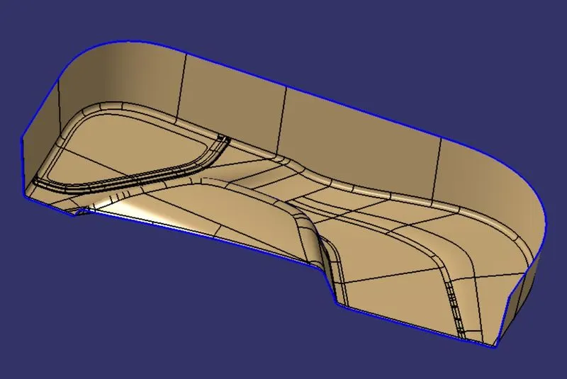
- Here I created Class B Surface on 2.5mm from Class A Surface.
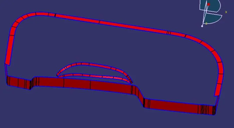
Class C Surface :- The Class C surface is the back side of a part of a surface that is permanently covered by another part.
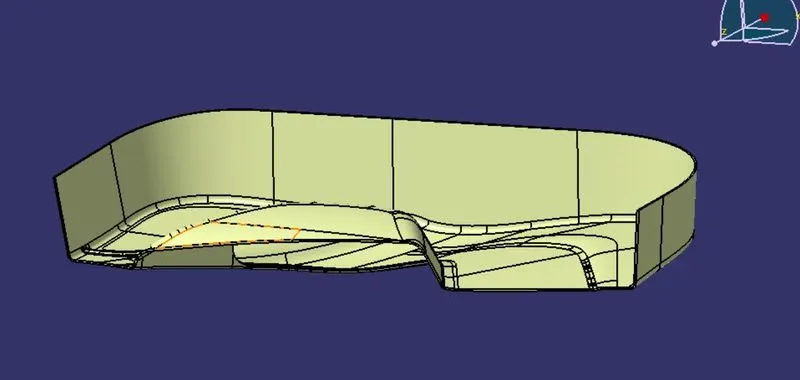
With the help of join and trim feature I have created a closed surface body.
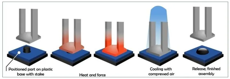
Heat Staking :- Heat Staking is a joining technology to join two or more parts together where at least one is made out of plastic. The process is used to melt and deform the plastic material using heat and force at a set process time.
How it works-
- The Hot Bar or thermode, with a defined cavity, comes down on the stud
- Force is applied on the stud and once the required force is achieved the heating process starts
- The force together with the pre-set heat will soften the stud and mold it into the required shape and at the same time fix the second part
- Cool down, still under force, to below glass transition temperature and finally lift the Hot Bar/thermode
Advantage of this :-
- Simplification of machinery
- Reduced cost of machinery
- Multiple fastening points
- Allows higher density of welds compared to hot air cold from or ultrasonic welding
Note- There are no any hard and fast rule for heat stake designing. At the designing time we should keep in mind keep some parameters like-
- Thickness of the top should not be very less otherise it could take sink mark due to thin thickness.
- Root diameter should not be so big that it could be happen sink mark.
- It height should be greater than locaters height.
- You can give 0.5 degree draft angle.
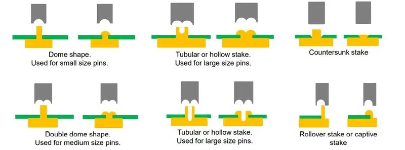
Variations in Heat Stake designs :-
- Dome shape
- Tubular or hollow stake
- Counter stake
- Double dome shape
- Rollover stake or Captive stake
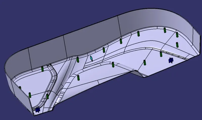
Designed Door Trim Component with 4 way locaters, 2 way locaters and heat steaks :-
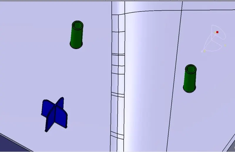
Draft Analysis of Final Part :-
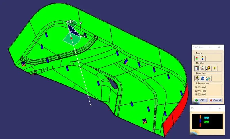
- Here I have given 3 degree draft angle. Some area is blue like heat stake, 4 way locaters, 2 way locaters because there is provided 0.5 degree draft angle.
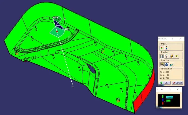
- When I give 0.49 degree draft angle then I found everything is ok.
Conclusion :- In this project we learnt that how to find tooling axis in appropriate way and how to create Class B and Class C Surface from Class A Surface. And mainly I learnt that how to create 4 Way Locater, 2 Way Locater, Heat Steak and apart from it's design parameters of this.
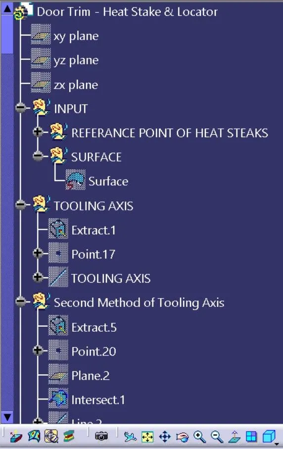
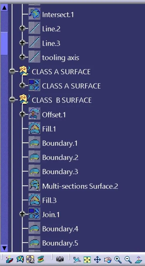
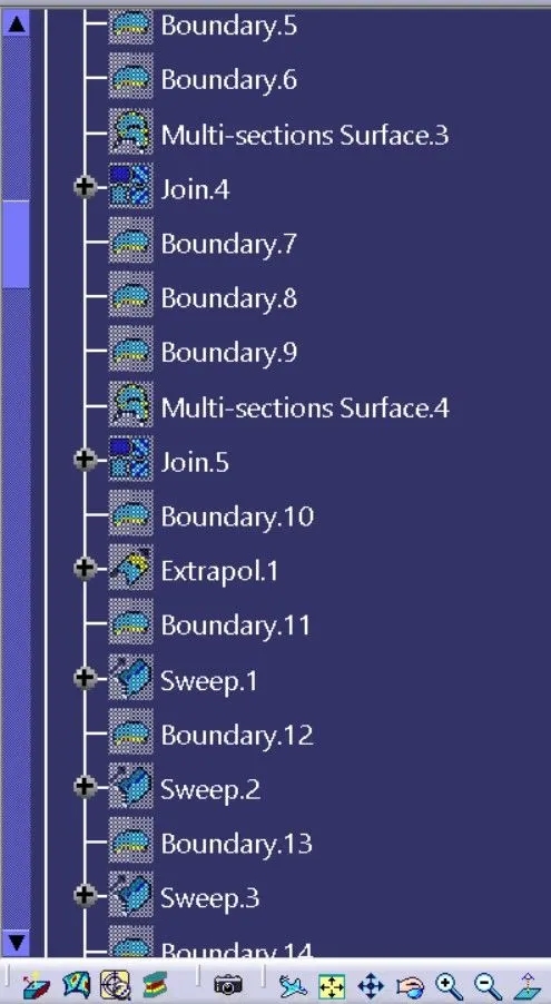
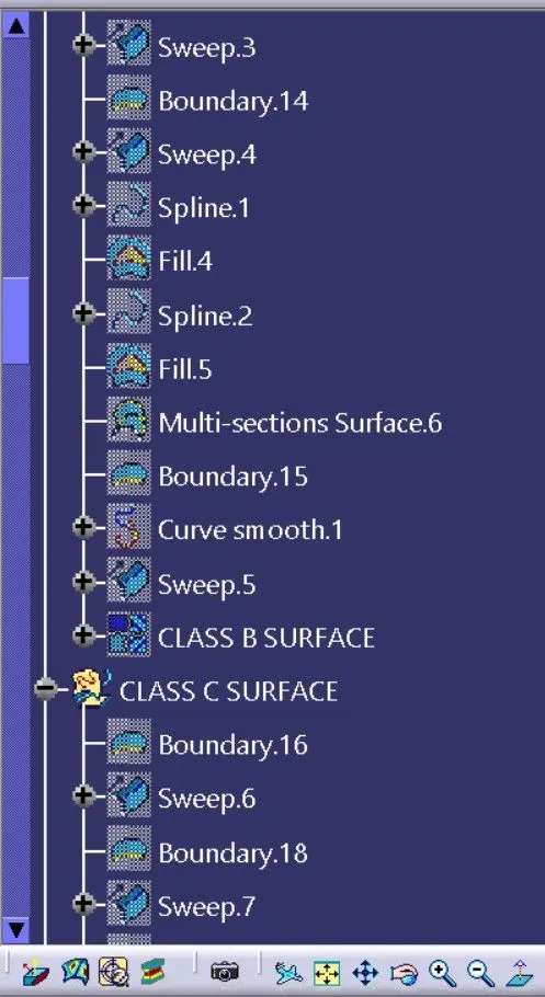
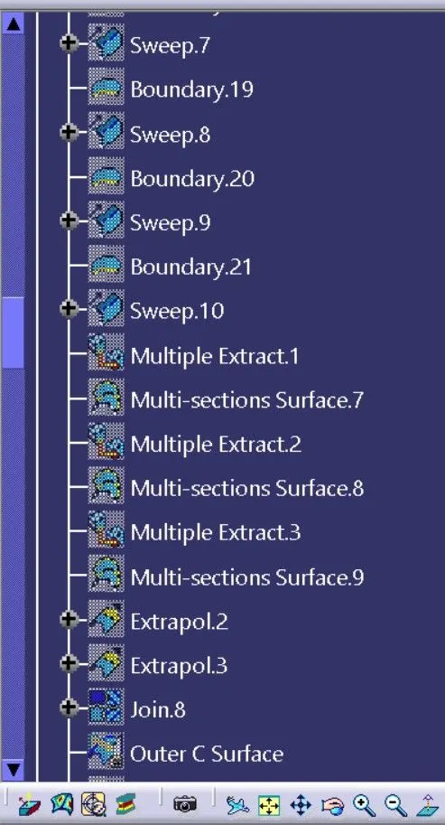
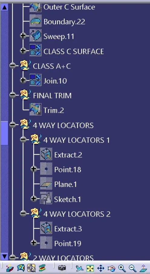
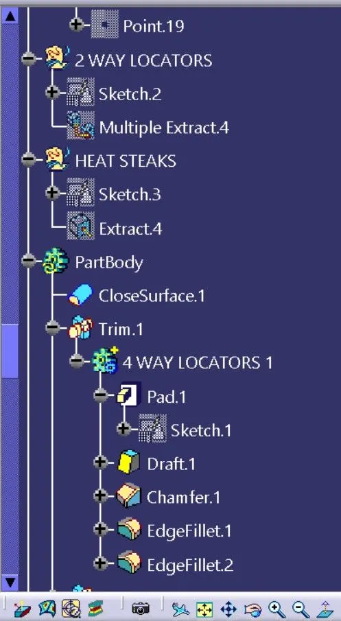
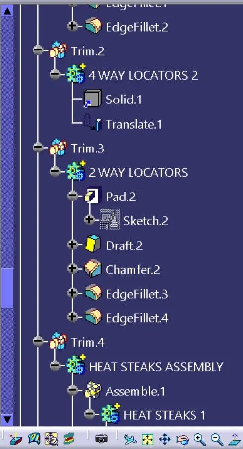
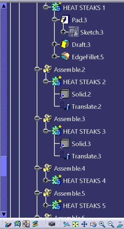
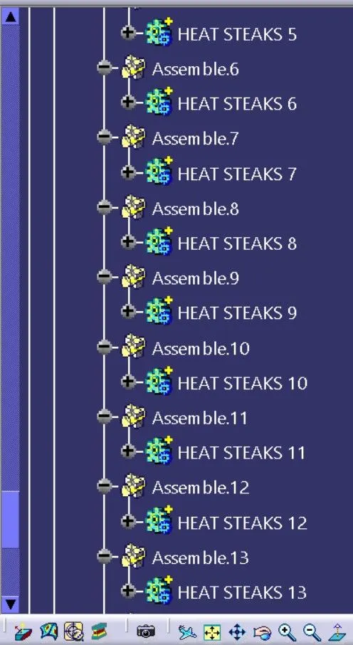
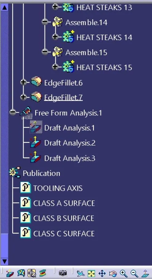
Feature Tree and Some Views of This Part :-