Photo Realistic Rendering
American Chopper Modelling Using SolidWorks
Objective:-
- To create a model of different part of Chopper.
- Assembly of different part of model for Chopper.
- Create a photorealistic model and render the model of the Chopper using Solidworks Photoview 360.
What is part modelling ?
Part Modelling is feature in which I create solid body and see the part that how to looking in reality, like as realise the vertuility. It uses different purpose. With the help of this I create many parts and assemble them and check it. If it is not correctly then I can change in part. And get a final part.
Part which is created for American Chopper :
The following part of the chopper is modelled by Solidworks and assembled them.
- Transmission Belt
- Kickstand
- Front Fender
- Rear fender
- Oil Tank
- Chain
- Pedal
- Front Wheel
- Rear Wheel
- Front Fork
- Chassis
- Engine
- Gas Tank
Now let us see the every part in detail.
- Transmission Belt :- In the Chopper transmission belt is used to transmit the power from engine to gearbox.
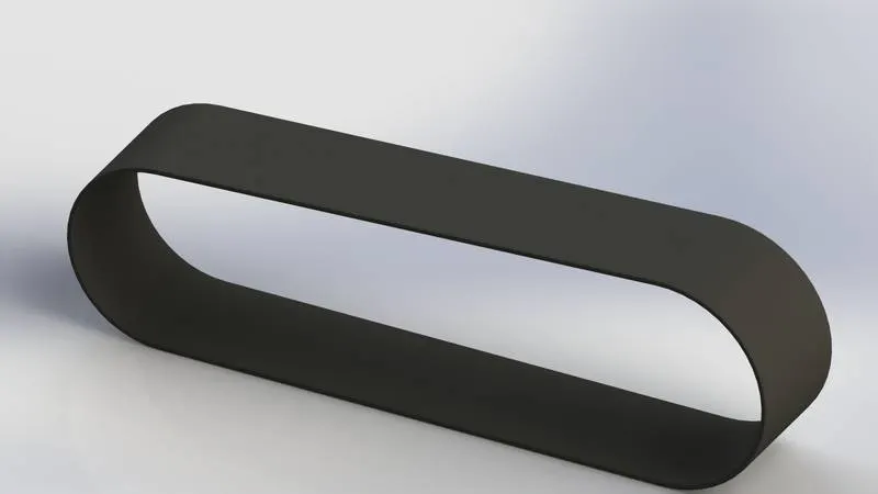
Feature is used to create the transmission belt.
- Sketch
- Offset
- Extrude
- Fillet
- Appearance
Sketch- Sketch is a 2D drawing representation respect to the plane in solidworks. It is a basic drawing. I draw a sketch with the help of line, arc, rectangle, circle, spline etc.
Offset- Offset is a feature with the help of this I draw entities with offset distance from reference which I select. I can select a many reference like line, arc, circle etc in one time.
Extrude- Extrude is a feature in which I convert 3D solid body from 2D sketch.
Fillet- Fillet is used to where the edge is on the body (external or internal). With the help of this I change the edge into circular edge.
Procedure followed to create the model of transmission belt.
- First of all I opened the solidworks software. Then click the new part to create the model.
- Before draw the sketch I changed the default plane name as
- Front plane – Front Plane Transmission Belt
- Top Plane – Top Plane Transmission Belt
- Right Plane – Right Plane Transmission Belt
- Then Front Plane is selected to sketch.
- I draw a 2D sketch with given dimension and relation with fully defined. And create a duplicate sketch from some distance with the help of offset entities.
- After it I changed the 2D sketch to 3D body.
- Then I gave the fillet as required dimension. After it the model of transmission belt is ready.
- And then I saved with part name as Transmission Belt.
- Kick-stand :- Kickstand is used when the bike is on rest (stand) position. With the help of this I can stand the bike anywhere on plane surface.
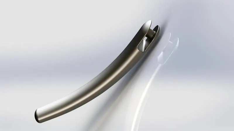
Feature is used to create the Kickstand.
- Sketch
- Loft
- Dome
- Boss Extrude
- Cut Extrude
- Split
- Fillet
- Plane
Where as
Loft - In this feature I create a solid body with complex geometry as various cross-section. The face is considered as Loft profile.
Dome - With the help of this entity I create a dome on regular or irregular shape. The centre of dome is outside from face.
Cut Extrude - It is work on opposite as extrude ( Boss extrude). With the help of this I cut the extruded body.
Split – Split line tool is used to project an entity on other surface.
-
Front Fender :- Front fender is that part of Chopper which is used to cover the front wheel. It is mounted on front fork. It protect from debris and waste particle which is flow by moving front wheel on running condition.
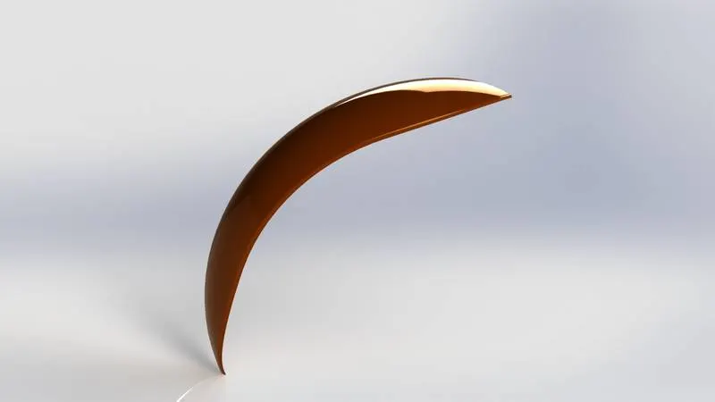
Feature is used to create the model of Front Fender.
- Sketch
- Offset Entities
- Trim Entities
- Revolve
- Dynamic Mirror
- Split
- Fillet
- Appearance
Where as ,
Trim Entities – With the help of this tool we trim (cut) or extend the line, curve etc. It works by which option we used like Power trim.
Revolve – It work like as extrude but it work on around an axis which I select.
Dynamic Mirror – With the help of this entity I mirrored a sketch which I select.
- Rear Fender: – Rear Fender is used same as front fender. It is the cover above rear wheel and mounted on rear part of chassis.
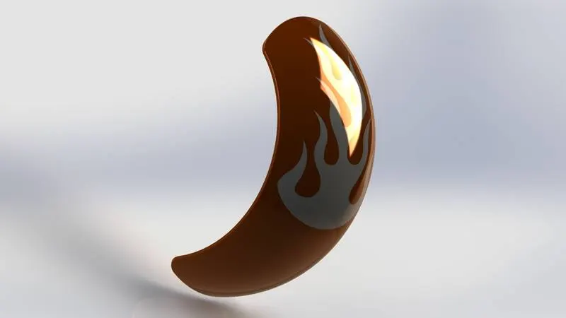
Feature is used to create the model of Rear Fender.
- Sketch
- Offset Entities
- Trim Entities
- Revolve
- Split
- Fillet
- Appearance
Where as ,
Appearance – It defines visual properties of the model like colour, texture etc. It is not used to change the material properties.
- Oil Tank :- Oil tank is the part of Chopper. The fuel which is required to running of chopper is stored in oil tank.
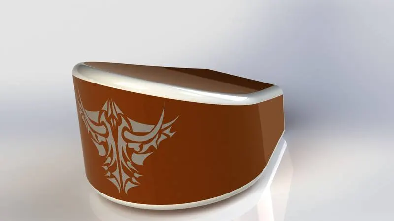
Feature is used to create the Oil Tank.
- Sketch
- Extrude
- Fillet
- Combine
- Shell
- Appearances
Where as ,
Combine - Combine is a property by which we combine two or more bodies.
Shell - Shell is special tool. With the help of this I create hollow in solid body.
- Chain :- Chain is a type of transmission system. In the Chopper model it is used to transmit the power from gear box to rear wheel.
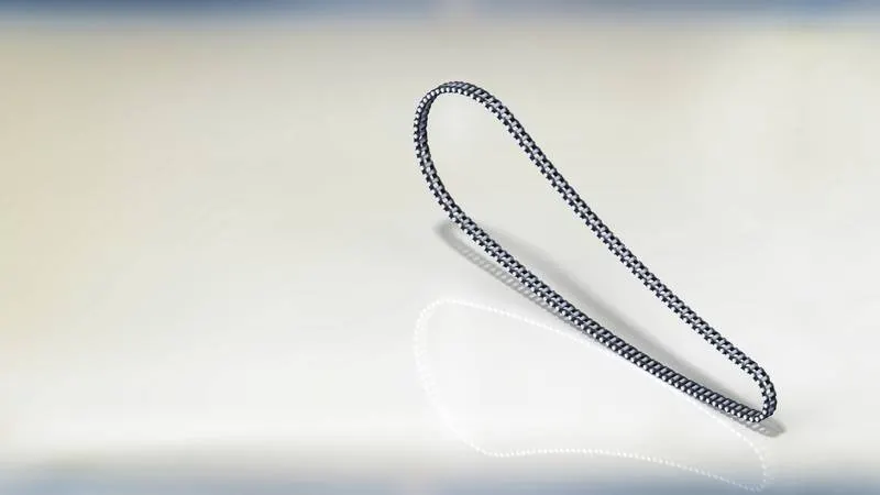
Feature is used to create a Chain model.
- Sketch
- Trim
- Fillet
- Blocks
- Extrude
- Patterns
- Appearances
Where as ,
Blocks - You can draw a blocks or sketch and save it, edit it. It is often used in sketch many times. With the help of this I can insert many blocks.
Patterns - The driven pattern is used to create pattern on planer or 3D curve. In Chain part the base sketch is like curve, circle. So I have used a Curve Driven Pattern.
- Pedal :- Pedal is a external part of Chopper which is attached with chassis. It is provided for comfortability of rider to placed his leg.
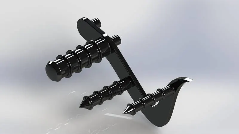
Feature is used to create the Pedal.
- Sketch
- Extrude
- Fillet
- Linear Pattern
- Dome
- Chamfer
- Appearances
Where as ,
Linear Pattern - Linear pattern tool is a kind of pattern tool. It works as circular pattern but slightly difference. This pattern works on linear basis.
- Front Wheel :- The Chopper model is moving on wheel means it travels by wheel. The front wheel is made of steel alloy material. On above the tyre is covered.
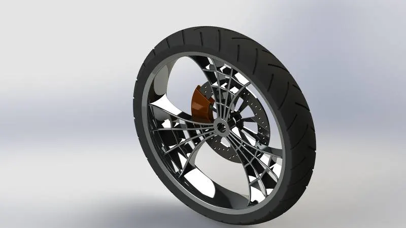
Feature is used to create a model of front wheel.
- Sketch
- Revolve
- Trim
- Fillet Entities
- Boss Extrude
- Revolve Cut
- Linear Pattern
- Chamfer
- Fillet Feature
- Extrude cut
- Circular Pattern
Where as ,
Chamfer - Chamfer is nothing but like as fillet. In chamfer I make an edge into flate with angle as chamfer.
Circular Pattern - In this feature I create a pattern in circular basis. With the help of this I create a grooves in tyre.
- Rear Wheel :- Rear wheel same as front wheel but in this wheel the chain sprocket is attached. By chain sprocket power is transmitted from gear box to rear wheel. Rear wheel is driver wheel where as front wheel is driven wheel.
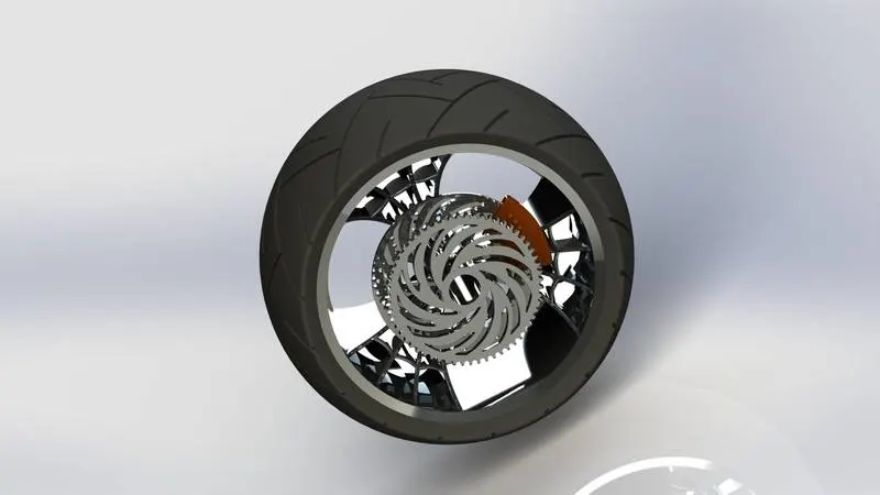
Feature is used to create the Rear Wheel.
- Sketch
- Revolve
- Trim
- Fillet
- Cut Extrude
- Circular Pattern
- Appearances
- Front Fork :– Front Fork is a part of Chopper. With the help of this we turn the bike in any direction with limited angle along a path. To bear the impact due to road imperfection the spring or hydraulic suspension is included in it.
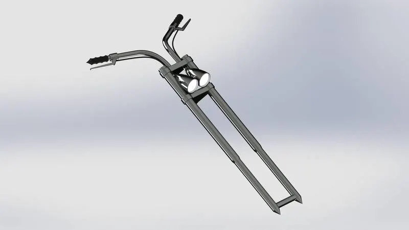
Feature is used to create the model of Front Fork.
- Sketch
- Extrude
- Trim
- Revolve
- Split
- Plane
- Convert Entities
- Body-Move/Copy
- Mirror
- Dome
- Combine
- Projective Curve
- Sweep
- Appearances
Where as ,
Body-Move/Copy - BY this tool entity we can copy the body and move it where we want.
Mirror - With the help of mirror we select the body and mirrored along a plane which I select.
Projective Curve - Projective Curve is a 3D curve which is projected by two different 2D curve.
Sweep - By this feature we can create a shape by moving 2D sketch profile along a path.
- Chassis :- Chassis is a base frame of bike. It is made by strong material. We attach the engine, front fork, rear wheel, seat etc on the chassis.
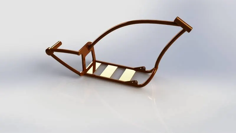
Feature is used to create the model of Chassis.
- Sketch
- Offset
- Convert Entities
- Projective Curve
- Trim
- Plane
- Sweep
- Split
- Revolve
- Cut Extrude
- Fillet
- Combine
- Appearance
- Engine :- Engine is a part of Chopper. It convert a chemical energy to mechanical energy. Which is transferred to gear box. And gear box is connected to rear wheel sprocket by chain then mechanical power is transferred to rear wheel so the bike is move on road.
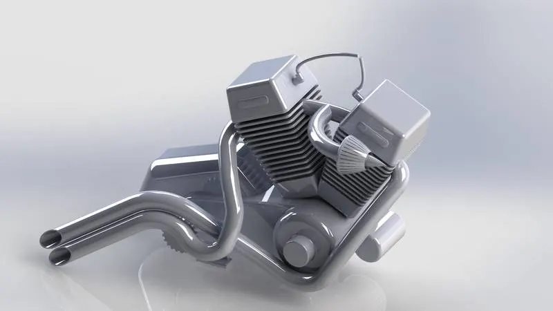
wheel so the bike is move on road.
Feature is used to create the model of Engine.
- Sketch
- Convert Entities
- Trim
- Revolve
- Boss Extrude
- Cut Extrude
- Offset
- Dome
- Fillet
- Projective Curve
- Composite Curve
- Sweep
- Mirror
- Circular Pattern
- Split
Where as ,
Composite Curve - With the help of this feature we composite 2 different curve into single curve.
- Gas Tank :- It use to store the gas which is required to run the engine.
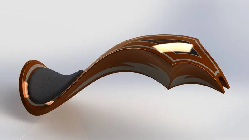
Feature is used to create the Gas Tank.
- Sketch
- Trim
- Project Curve
- Convert Entities
- Sweep Surface
- Loft Surface
- Fill Surface
- Surface Trim
- Surface Knit
- Sweep cut
- Fillet
- Appearances
Where as ,
Loft Surface - With the help of this tool we create a surface by 3D curve.
Sweep Surface - It is used to create section position surface along a path.
Fill Surface - This feature construct the surface patch with any number of side, within a boundary existing by edge, side or curve.
Surface Trim – By this tool we trim (cut) the surface where I want.
Surface Knit - Surface Knit is used to knit the 2 free edge of the surface together. It also reduce the gap between two surface.
Assembly of Chopper Model :-
First of all I inserted the chassis part in assembly feature in environment. After that I fixed the chassis. Then I insert the every part one by one and assembled the part with chassis by mate tool.
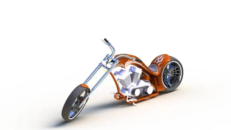
Feature is used to assemble the Chopper Model.
- Insert
- Mates
Where as ,
Insert - Insert is a option by which we insert the part of model.
Mates - Mates is a geometrical relation combination. With the help of this we mates the part as possible relation. We can move a component within degrees of freedom.
Photo Realistic Rendering :-
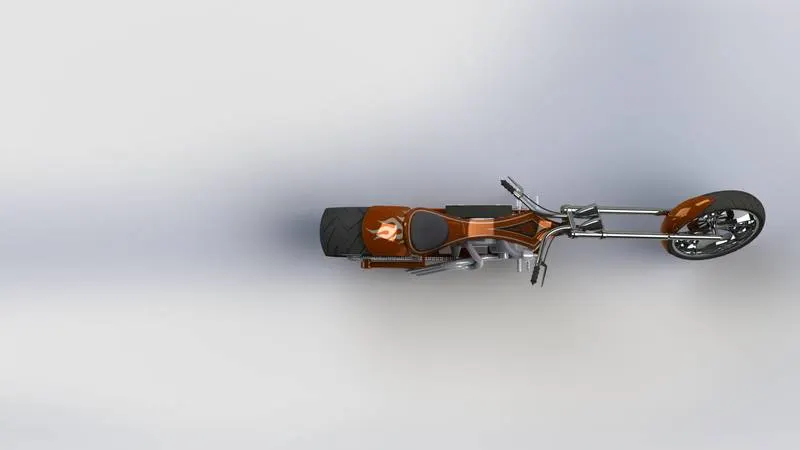
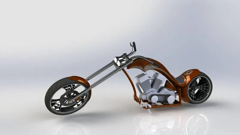
- Rendering is the process of creating realistic image of the Photorealistic model with the environment.
- Rendering has been done in two ways in solidworks.
- Photoview 360
- Solidworks visualize
- In the photorealistic model some of the mate condition and position are changed to render realistic model.
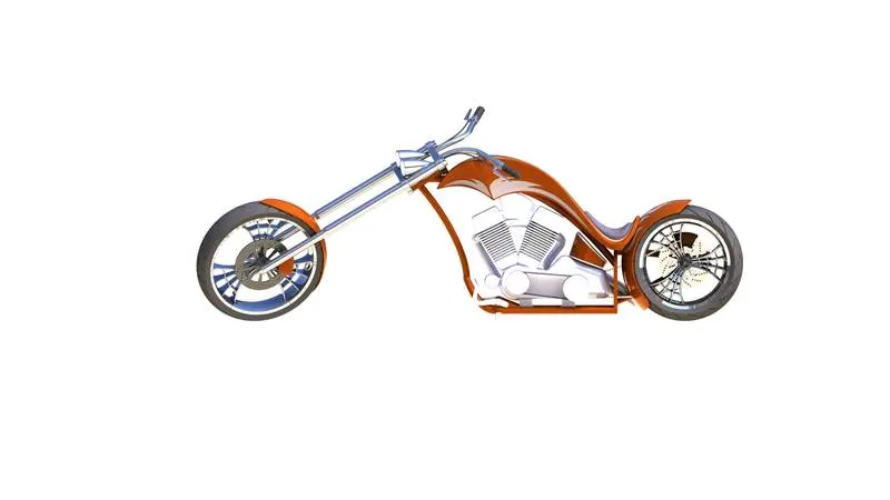
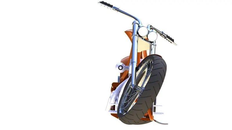
- Then realistic model is rendered into realistic image with different views.
Here are some Rendered images-
Conclusion :
- The parts of the Chopper are modelled using most of the Solidworks modelling tool in solidworks.
- The parts are inserted into assembly environment and Chopper is assembled using assembly module of solidworks.
- The realistic image was rendered with the use of Photoview 360 & Solidworks Visualize.