Week 9 - Project 1 - Door Trim Lower with Engineering Features
DOOR TRIM LOWER
Aim : To Create the Door trim lower component through the given Class-A surface.
Objectives :
- Creation of proper tooling axis considering the required draft angle of a component
- Performing draft analysis on the given Class A Surface and then final component
- Creation of Class B and Class C Surface
- Adding the Heat stake and locators to the Door Applique trims
- Work on to write a detailed report based on the Draft analysis result and add the images required.
Final Look As given Below which is mentioned in the question :
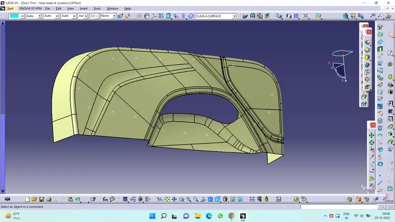
Given Class A Surface :
Tooling Axis :
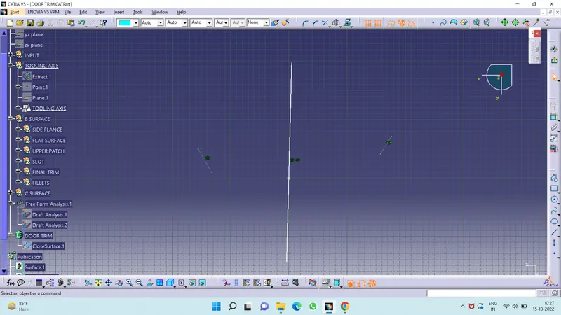
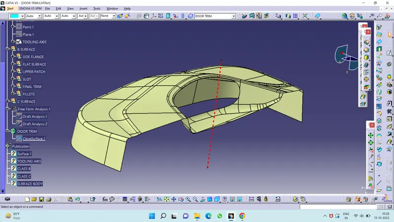
It is defined as the direction in which the mould/core and cavity open. Selection of the direction of the tooling axis depends on the ease at which components can be easily ejected.
By analysing the component the most easily ejectable direction is somewhere close to the Z direction,(might be inclined to it) so we have made a sketch on the YZ plane of Axis System) to create a bisecting line considering the 2 faces which might be difficult to be tooled.
One more sketch is created on the ZX plane of Axis System for considering the lone side face for tooling direction. In the sketch, a line is drawn with a suitable angle to the lone side face so that with the resultant tooling axis the side face is cleared.
Procedure to find Tooling Axis
- Check for any openings in the given model Door Applique by using BOUNDARY. In BOUNDARY > select edges - select the surface to create the boundary at the openings.
- Create a point at the center of the surface by using Point Definition by Point Type - on the surface,Surface - select the surface, and Distance - 0
- By using the Line Definition option create a line in the Y direction by Line Type - Point-Direction, Point - select the point, and Direction - Y which will be the Main Tooling Axis.
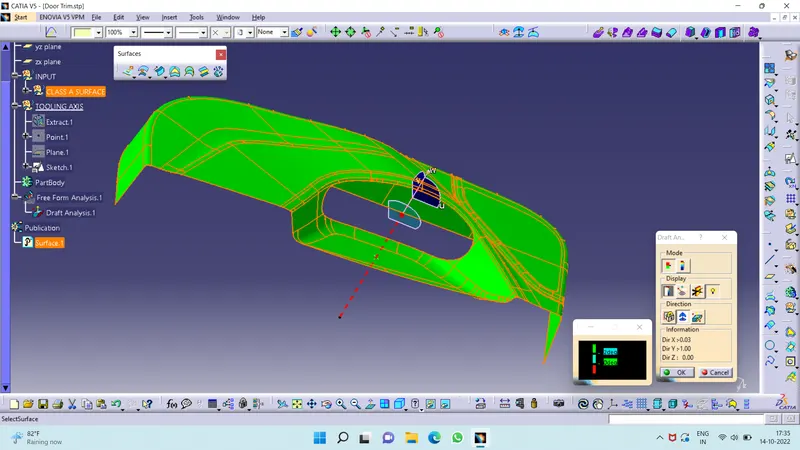
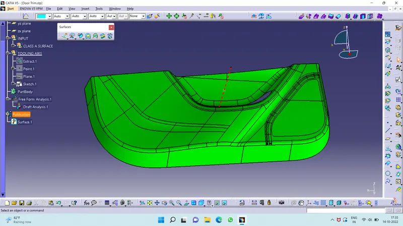
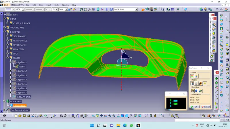
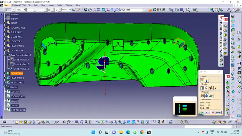
Draft Analysis: to check whether our tooling axis is proper or not we do the draft analysis.
- Go to insert > analysis > feature draft analysis.
- Align the compass with the tooling axis.
- Then, click on the Class-A surface to see if the it is within the permissible limit of the draft values.
- The Class-A surface should turn green and then draft value should be given as 3 degrees.
Class B Surface :
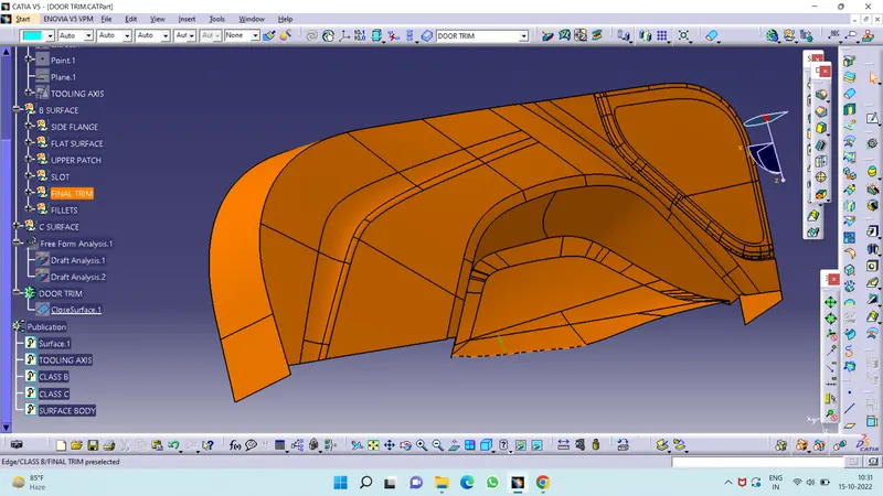
Procedure for Creating B Class Surface
- Extract the plane surfaces from the class A surface neglecting the fillet surfaces.
- Untrim the surfaces from the extracted surfaces to get the actual shape of the surfaces.
- The Untrimmed surfaces should be intersecting with each other. If not intersecting extrapolate the surfaces.
- The thickness of the component is to be maintained at 2.5mm. So Offset the Extrapolated surfaces setting 2.5 mm as the offset value.
- Trim the surfaces as per the shape of the Class A surface.
- Create fillet for the component as per the class A surface. Measure the edge of the fillet value from the class A surface by extracting the fillet surface and untrimming the surface.
- Create fillets for the class B surface and make sure the thickness between the fillet surfaces are maintained the same as the remaining surfaces.
Class C Surface :
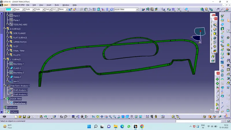
Procedure for Creating C Class Surface
- Extract the edge lines for the class A surface using multiple extract option.
- To create a sweep, there should be a boundary created to it. The boundary should be created separately as creating the boundary completely doesn’t create the sweep smoothly as the model contains the main unnecessary lines.
- To cover those, the smooth option is used to create the smooth surface and the Class A surface model is swept smoothly over the plane areas. Over the draft angled areas, the boundary should be created separately to create the sweep over that area.
- Create edge surface form class A surface using sweep option. Set the sweep mode to draft direction, select the extracted lines as guide curves and the tooling axis as the draft direction. Set the sweep angle as 3 degrees and the length of sweep more than 2.5 mm.
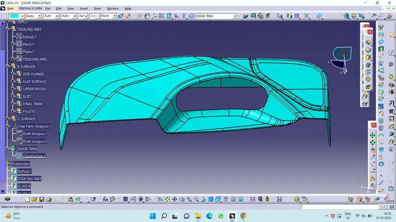
Surface Body (A+B+C) : we create the final solid body using the Closed Surface command.
- Go to Boundary command and click on the new surface. An error dialog-box should pop-up.
- Go to the Part Design workbench.
- Select the Closed Boundary option and then click on the generated surface.
- A closed solid body is obtained.
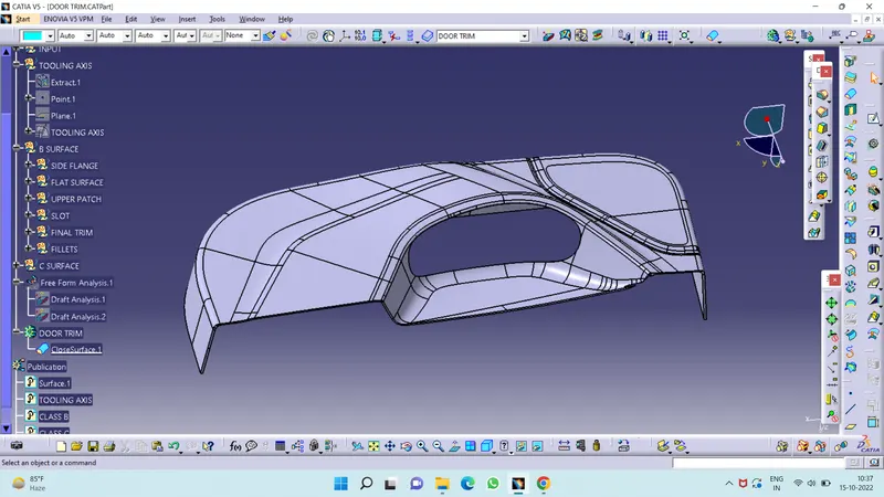
Close body Part :
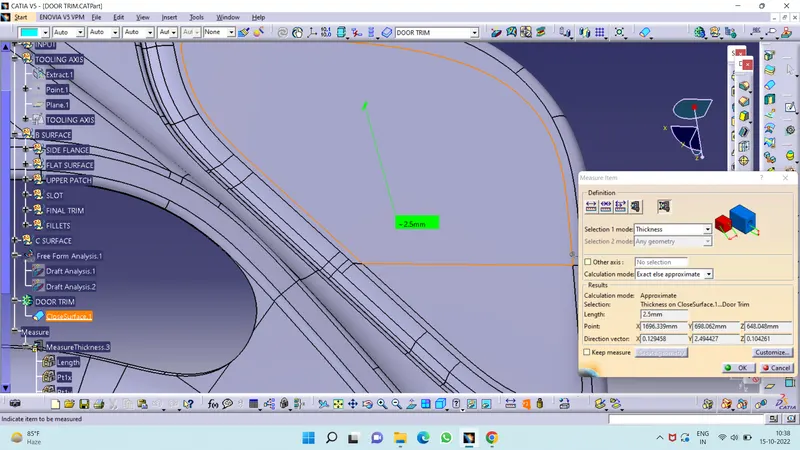
Thickness : 2.5mm
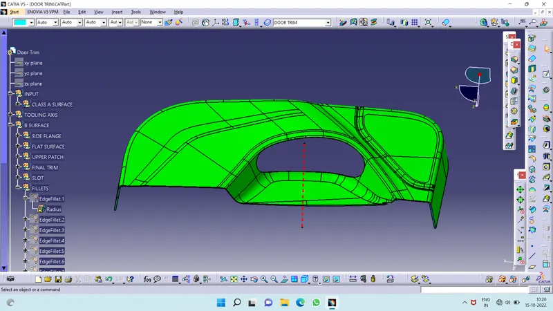
Draft Analysis of Close Body :
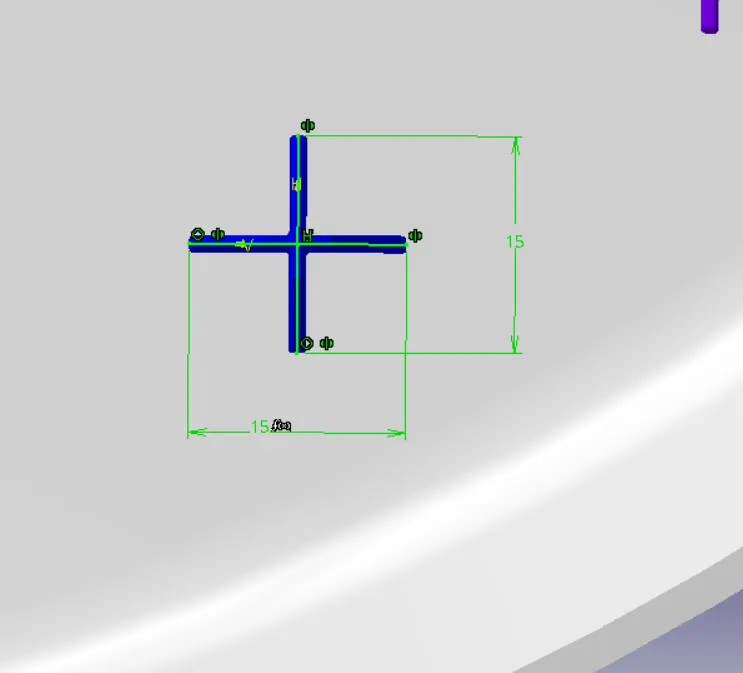
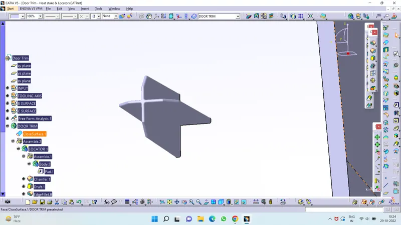
CREATION OF LOCATORS:
To create the locators,
- I created a sketch on the body.
- After creating the sketch, I pad it 0mm in height and thicken it to 1.3mm and
- I drafted it with 0.5deg in the direction of the tooling axis.
- I gave 3mm of chamfer with 45deg of inclination and after
- I gave a fillet of 0.3mm radius.
4-way locator:
CREATION OF HEAT STAKES:
To create the heat stakes, I draw a sketch on the surface. After the creation of the sketch, I pad it to 18mm height and I gave a draft angle of 0.5deg on both sides (inside and outside) and then I gave a fillet with a 0.25mm radius. After creating the heat stake, I created the ribs for supporting purposes. To create the ribs, I draw a sketch and padded it to 12mm in height and 1mm in thickness. After padding the ribs, I drafted 0.5deg in the tooling asix direction and filleted it with a 0.25mm radius. Finally, I union trim the ribs with a heat stake to remove the ribs, which are present inside the heat stakes.
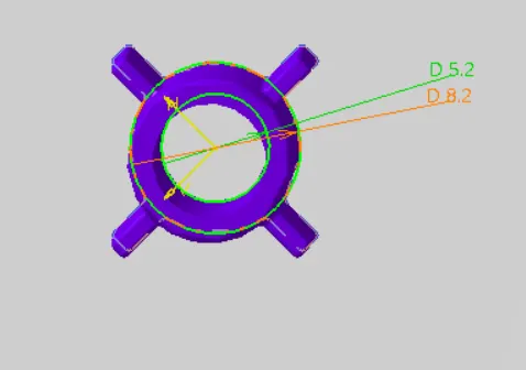
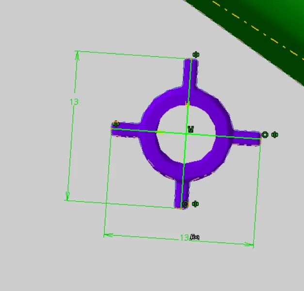
Heat stake with supporting ribs:
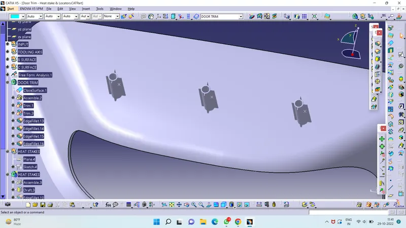
Now I Power copy the heat stakes by giving inputs like point and plane copy them in the part body according to the requirement.
CREATION OF RIBS:
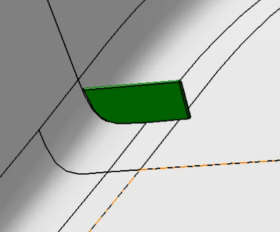
Ribs are a feature in plastic injection molded parts. They are thin extensions that run perpendicular from a wall or plane. They are commonly used to provide additional support and strength to a part. Thickness and location are essential to rib design.
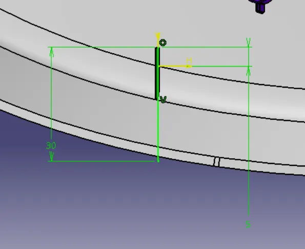
To create the ribs, I draw a sketch and padded it to 12mm in height and 1mm in thickness. After padding the ribs, I drafted 0.5deg in the tooling asix direction and filleted it with a 0.25mm radius.
use power copy to produce rib and another two ribs are produce using tranlate command to have command on both the steps.
CREATION OF DOG HOUSE:
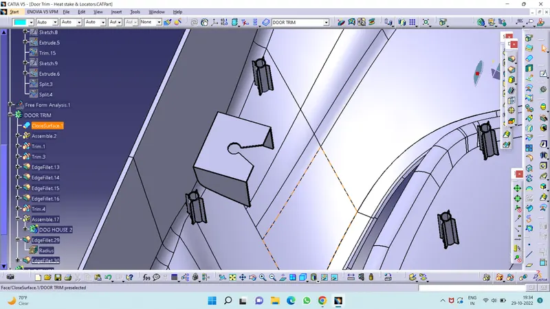
Dog house is an engineering feature used in plastic trim design. Dog houses are used as supporting feature. Sometimes other engineering features like snaps; locators etc. are mounded on them to increase their strength.
- To create the Dog house, I draw a sketch and padded it to 18mm in height .
- After padding in the direction of tooling axis, I drafted 3deg in the tooling axis direction and filleted it with a 3mm radius.
- Than i remove the material from the base of it having a thickness of 0.4*T=1 mm.
- Than provide draft it to 0.5degree in the direction of side core axis.
- Then shell the main padded structure to 0.7*T=1.75mm.
- Remove the second bbody from the first body .
- After joining both the bodies translate it to required points and rotate it with respect to its edge .
- After producing all the dog house unitrim it with the solid surface previously produced.
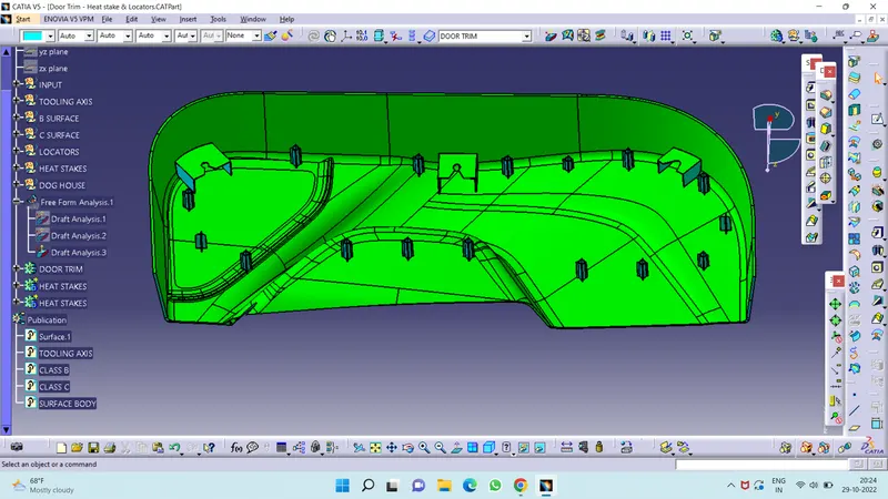
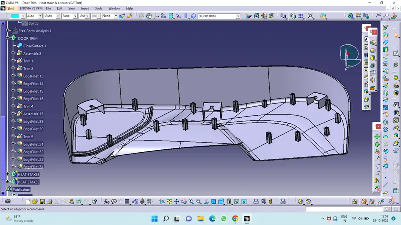
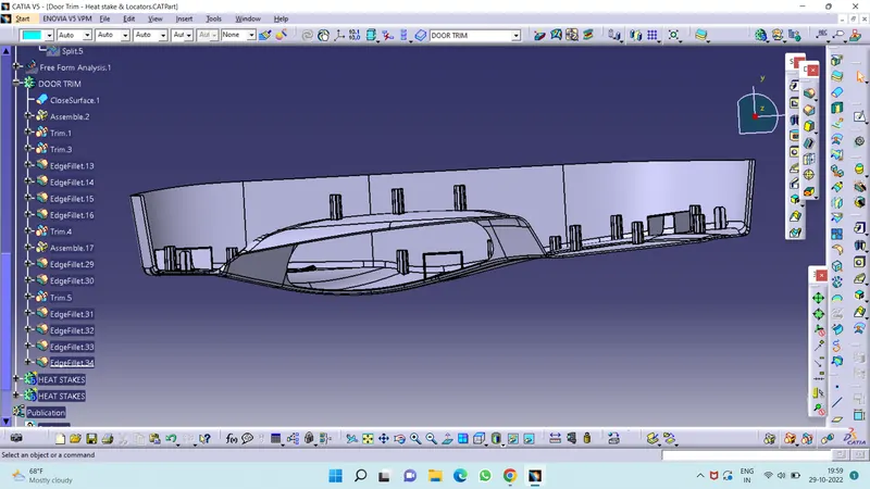
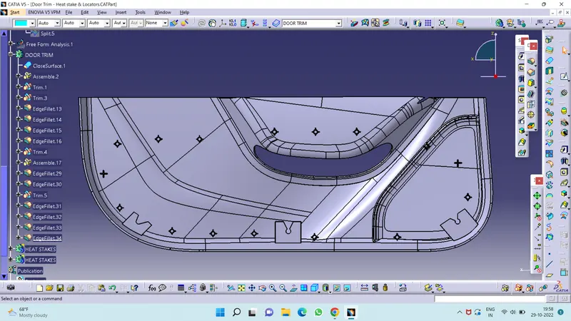
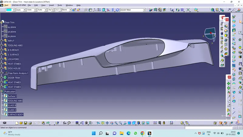
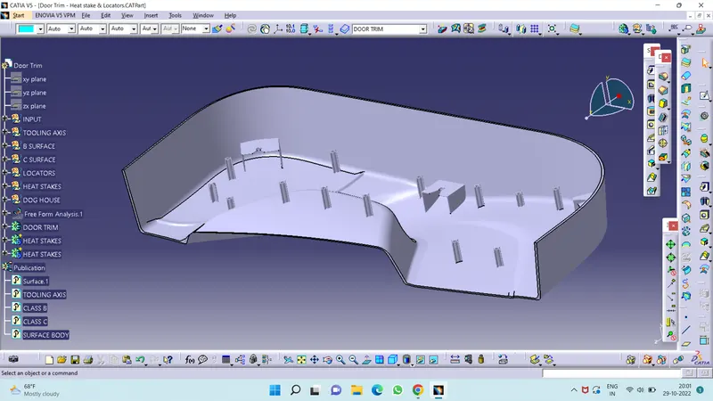
the final produced solid body having all the fetures is shown below...
Final Draft Analysis :
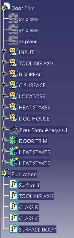
Tree Structure :
All Views of the Part :
Conclusion :
- The Door trim lower Plastic component through the given Class-A surface is created.
- The tooling axis for the given Class-A Surface should be created.
- The draft angle and at the end perform the Draft analysis on the model are done.
- Creation of Class B and Class C Surface are done.
- Adding the Heat stake and locators to the Door Applique trims are done.