Week 9 - Project 1 - Door Trim Lower with Engineering Features
AIM:
Create the Door Trim Plastic component through the given Class-A surface.
OBJECTIVES:
To begin with, the tooling axis for the given Class-A Surface should be created meeting the requirements of the draft angle and at the end perform the Draft analysis on the model. Take the Thickness of the component to be 2.5 mm and Create the Heat Stakes and the locators considering the design rules
GIVEN CLASS A SURFACE:
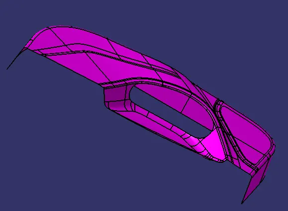
Class-A Surfaces
The aesthetic/free-form surface which constitutes the visible outer layer of a component can be termed as a Class-A Surface. In this project, the Class-A surface of a coin holder which is composed only of curvature continuous surfaces is used as the input for performing the draft analysis.
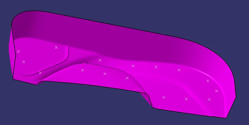
CLASS A SURFACE WITH POINTS:
Draft
To facilitate easy removal of components from the mold, it is necessary to add a taper all along the surface with reference to the tooling direction. This taper is termed as a draft and its value ranges from 0.5 degrees to 3 degrees, with the latter being the most widely accepted norm.
DRAFT ANALYSIS:
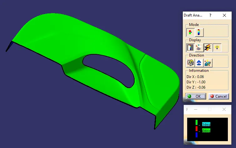
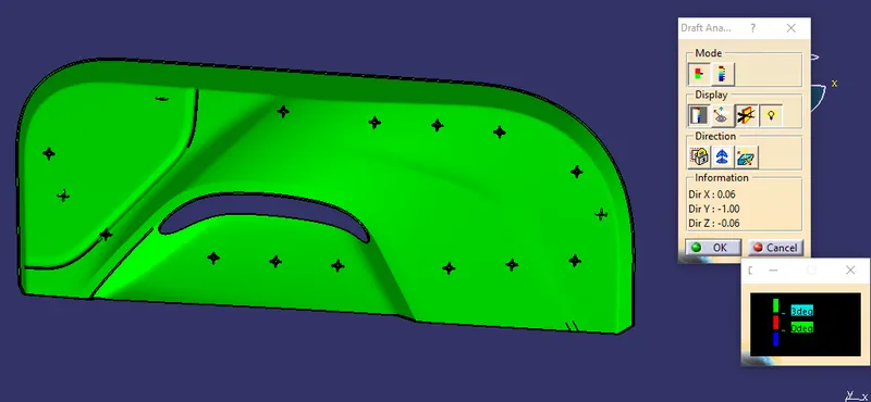
The Draft analysis command in CATIA enables to detect if the drafted part can be removed in an easy manner. This analysis is performed based on colour ranges identifying zones on the analyzed element where the deviation from the draft direction at any point, corresponds to specified values.
Tooling direction
The direction along which the core pulls apart from the cavity is termed as the Tooling direction.
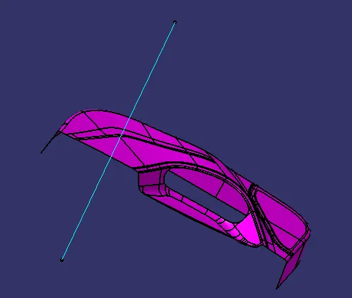
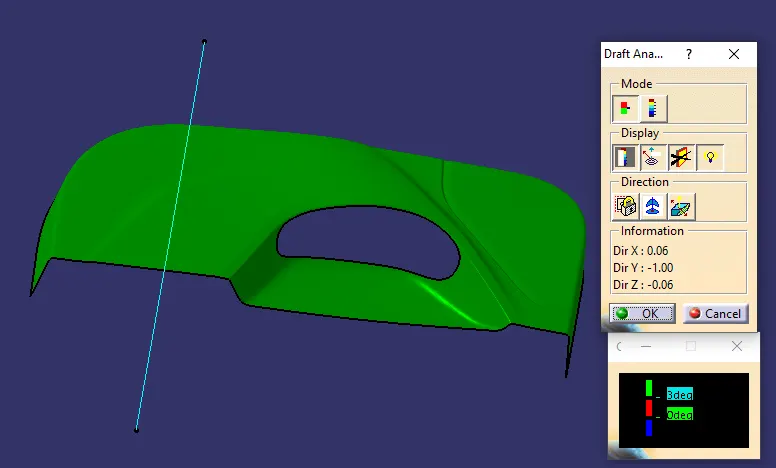
Since draft is measured with reference to a tooling axis, the first step after importing the model into CATIA was the creation of a tooling axis. To incorporate for tool clearances due to the presence of tapered surfaces in the part. Extracting the flat surface on the class A surface and creating the line normal to the surface, and we will check the draft analysis wether it meets our reqirements or not.
Draft Analysis
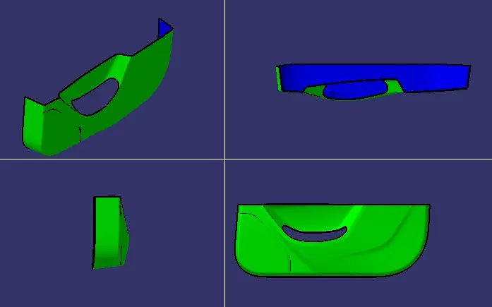
The draft analysis command in CATIA helps to detect whether the drafts provided in the model will facilitate easy removal of the component during manufacture.
This analysis is performed based on colour ranges identifying zones on the analyzed element where the deviation from the draft at any point, corresponds to specified values.
- When the draft angle value of the surface is equal or smaller than a graduated value, the color below the graduated value is applied
- When the draft angle value of the surface is greater than the greatest graduated value, the color above this graduated value is applied
In this project, the required draft for all surfaces were chosen as 3 degrees.
Creation of B-surface:
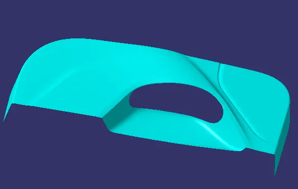
- Once the analysis on the class-A model was done the next step was to create the B-Surface for the model
- The Class-A Surface features were analysed and according to the B-surface creation procedure followed in this project, different regions were selected and assigned different colours and appropriate names
- he surfaces to be made into the B surface were first extracted using the extract tool
- To remove dependencies with the original surface, these extracted surfaces were then made independent using the tool
- In order to join these independent surfaces, they needed to be extended to form interference between adjacent surfaces. For this the extrapolate tool was used
- To remove unwanted extensions in the surfaces after interference, the trim tool was used and the result was a single surface
- Since the idea behind creation of a B surface is to have an offsetted surface from the input class A surface, the next tool used was the offset tool.
creation of c-surface:
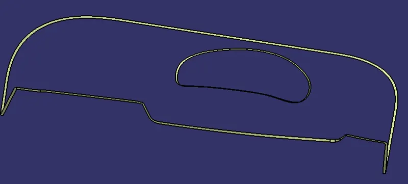
- The C surface forms the connection between the Class-A and B surfaces and is essentially the thickness of the final component
- The C surface was formed using the sweep tool
- For this command, the side flanges and its boundary were extracted from the Class-A Surface and then swept to form the C surface
creation of B+C-surface:
CREATION OF A+B+C SURFACE:
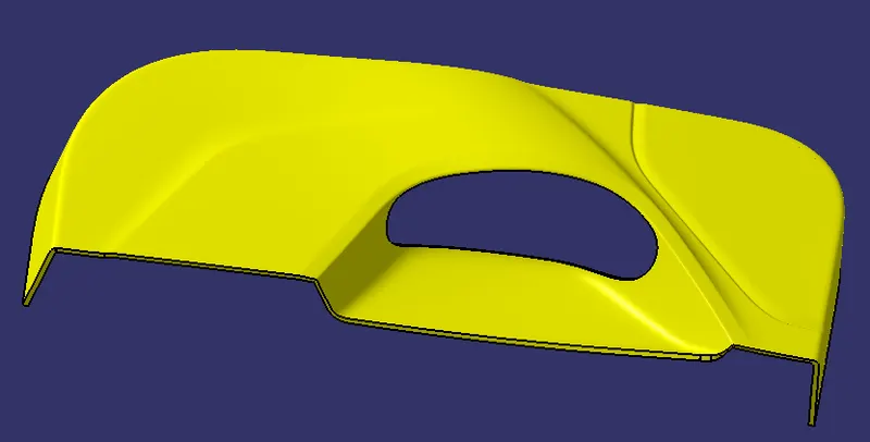
To create the final surface model, the B and C surfaces were first trimmed and joined together using the trim toolThe combined surfaces were then joined with the Class-A Surface using the join tool to create the final surface model.
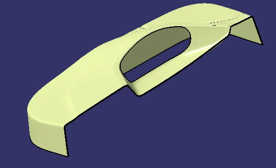
FINAL BODY:
- Before converting the surface model into a solid model, the part was first opened using in the part workbench
- The close surface tool was used to convert the surface model into a solid model
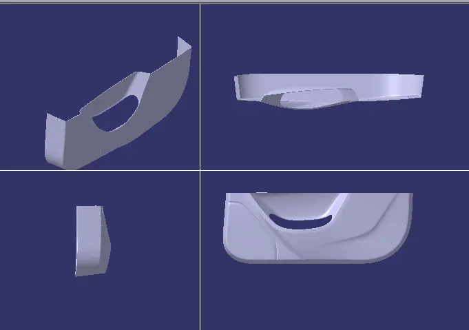
DRAFT ANALYSIS ON FINAL BODY WITH OUT HEAT STAKES AND LOCATORS:
Similar to how the draft analysis was done on the Class-A surface, a separate analysis was done for the solid model as well, with respect to the main tooling axis
CREATION OF LOCATORS:
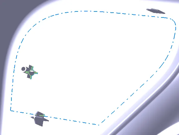
To create the locators, I created a sketch on the body. After creating the sketch, I pad and thicken it to 1.0mm and I drafted it with 0.5deg in the direction of the tooling axis. I gave 6mm of chamfer with 45deg of inclination and after I gave a fillet of 0.5mm radius.
4-way locator AND 2-way locator:
CREATION OF HEAT STAKES:
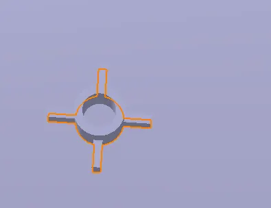
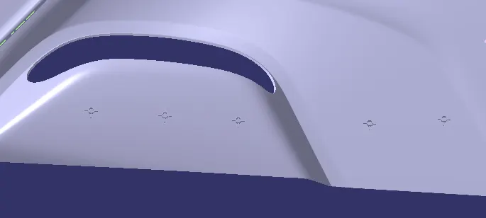
To create the heat stakes, I draw a sketch on the surface. After the creation of the sketch, I paded and I gave a draft angle of 0.5deg and then I gave a fillet with a 0.5mm radius. After creating the heat stake, I created the ribs for supporting purposes. To create the ribs, I draw a sketch and padded and 1mm in thicken. After padding the ribs, I drafted 0.5deg in the tooling asix direction and filleted it with a 0.5mm radius. Finally, I union trim the ribs with a heat stake to remove the ribs, which are present inside the heat stakes.
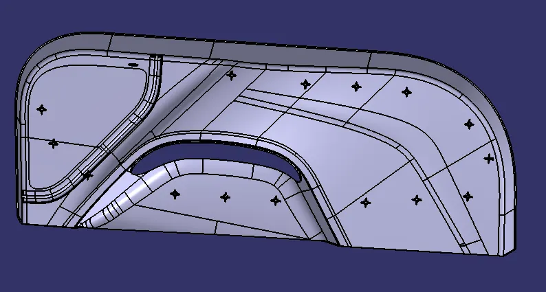
Now I translated the heat stakes by copy-pasting them in the part body and translated point to point as per given points..
Final part body with 4-way and 2-way locators and all the heat stakes with ribs:
DRAFT ANALYSIS FOR FINAL PART BODY :
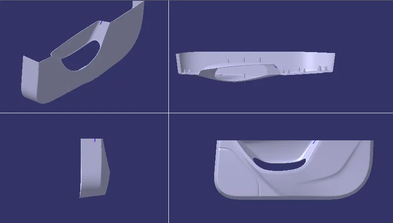
MULTI VIEWS OF FINAL MODEL:
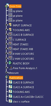
FINAL TREE: