Week 9 - Project 1 - Door Trim Lower with Engineering Features
Door Trim Lower with Engineering Features :-
Aim-
Create the Door Trim Lower Plastic component through the given Class-A surface. To begin with, the tooling axis for the given Class-A Surface should be created meeting the requirements of the draft angle and at the end perform the Draft analysis on the model. Create the Heat Stakes and the locators considering the design rules.
Heat Stakes design-
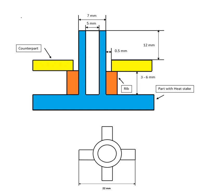
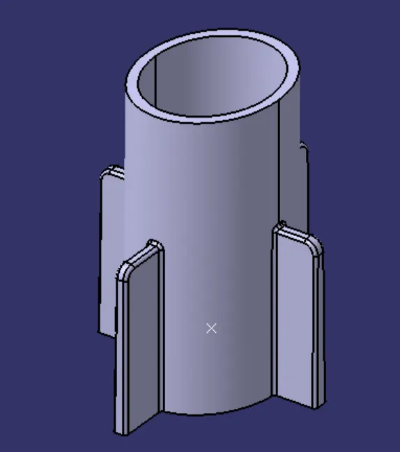
- Counter Part Thickness - Will be given as input
- Component Wall Thickness - Will be given as input
- Length of the Rib - 20 mm
- Height of the Ribs - 10 mm
- Inner Diameter of Heat Stake (d) - 5 mm
- Minimum clearance between heat stake and counterpart - 0.5 mm
- Height of the Heat stake - Depends on the rib height and counter-part thickness
- Minimum fillet of Heat Stakes - 0.25 mm
- Minimum Draft Angle of Heat Stakes - 0.5 degrees
Locator-
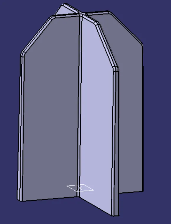
- Height of the locators should be 2 mm to 5 mm greater than the heat stakes
- Thickness, fillet and draft angle are of same as rib design rules.
- Ideal Chamfer value - 5 mm x 45 degrees
- Ideal length of the locators - 25 mm
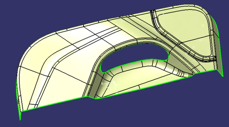
Given Class A Surface-
Class B Surface-
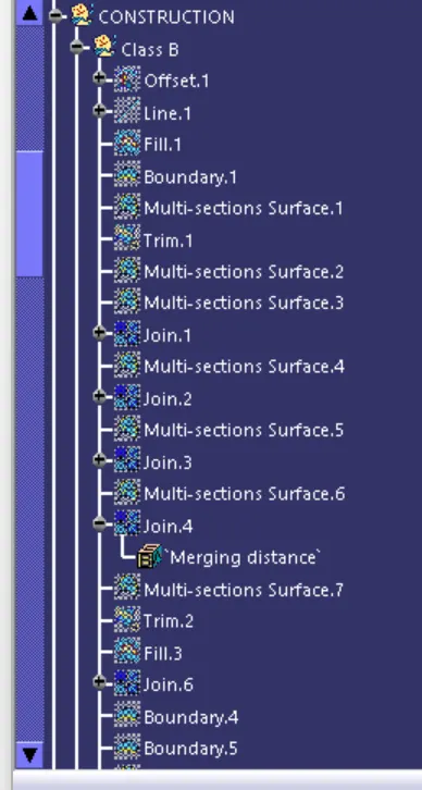
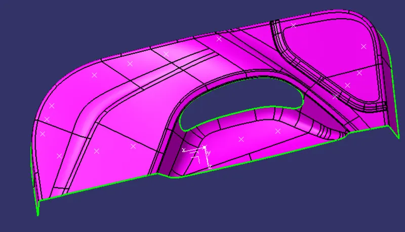
To create class B surface offset the class A with proper direction and distance. Here distance is the thickness of the component. As no given thickness is provided, so we are asuming the thickness value is 3MM. Reasult after offseting-
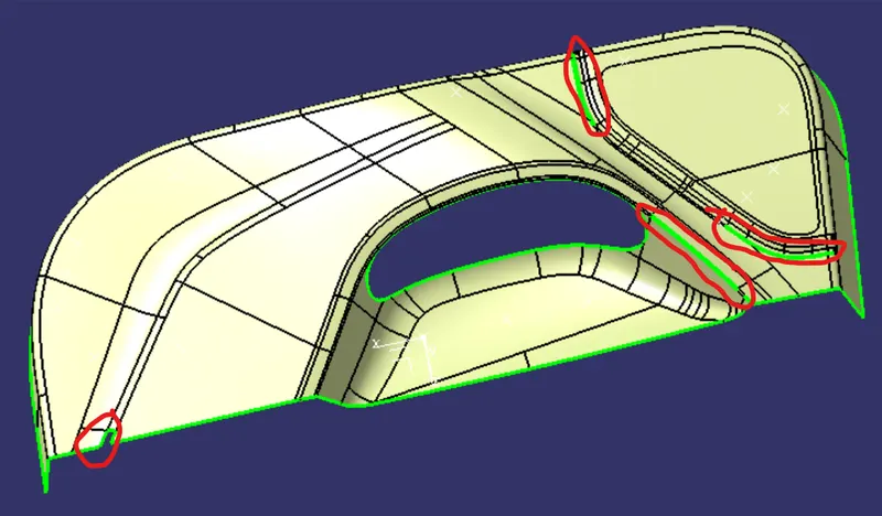
Perticulerly the marked area of the surface not offseted properly. So we will fill that area and the final surface is class B surface.
Class C Surface-
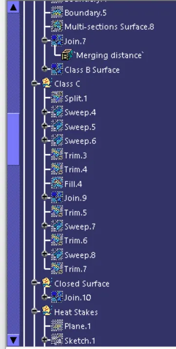
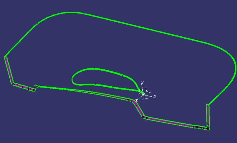
To create class C surface create boundary using class A surface boundary with 'Boundary' command in 5 parts. And use 'Sweep' command to create a surface that is in 90 deg. angle with class A surface. The reasulyent surface will be the class C surface.
Final Closed Surface-
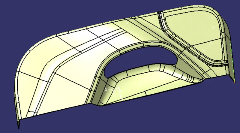
Class C surface trimmed with class B surface properly and joined with class A.
Solid Body-
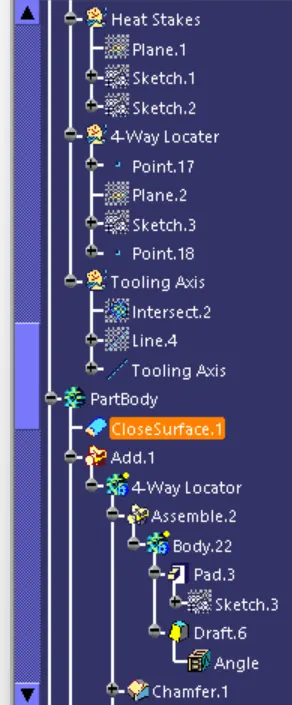
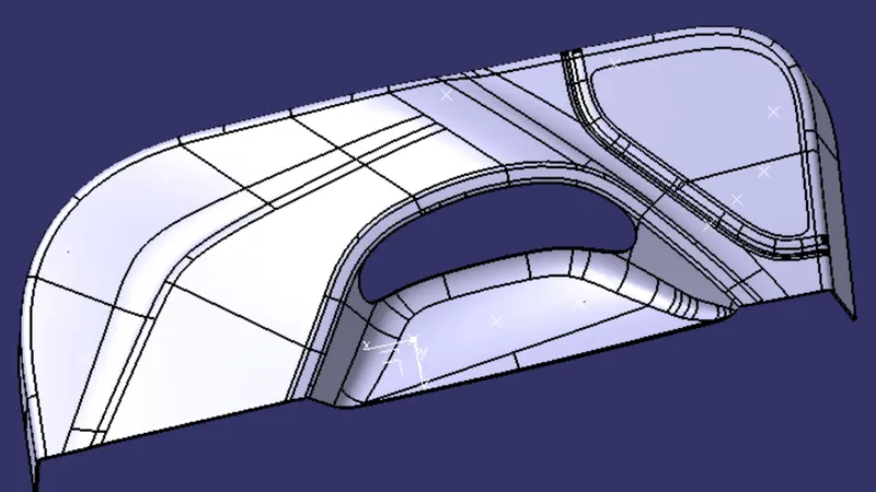
Using 'Closed Surface' command of Part Workbench we have to make make the body solid.
Draft Analysis-
Designers of plastic parts and mould tooling manufacturers can use the Draft Analysis tool to check the correct application of draft to the faces of their part. With draft analysis, you can verify draft angles, examine angle changes within a face, as well as locate parting lines, injection, and ejection surfaces in parts.
Tooling Axis-
For this case as no hole is concerned, so we will try to consider the perpendicular axis of that dented curved surface, for creating the tooling axis. So we will analyse perpendicular plane.
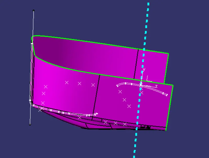
Class A Surface draft analysis-
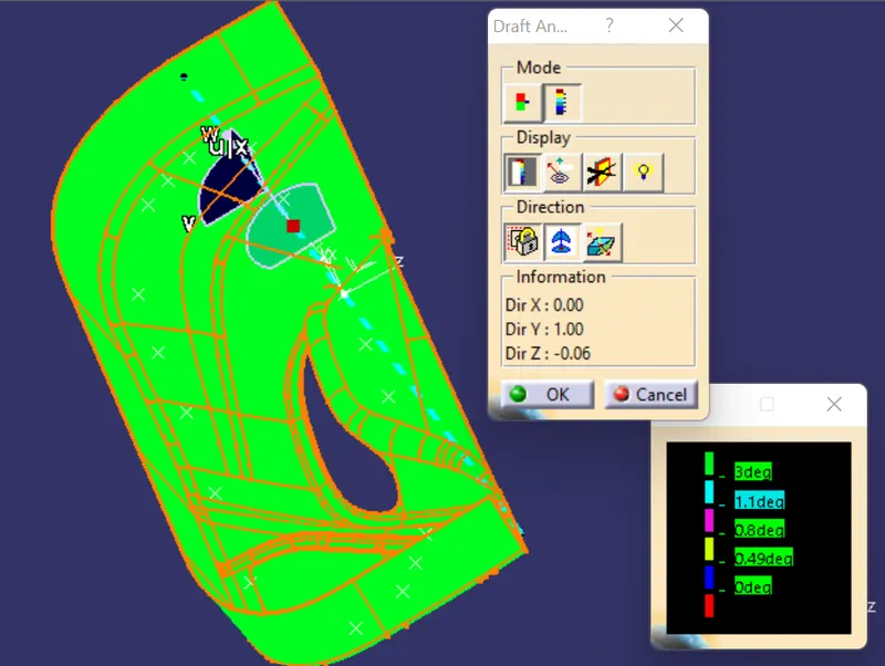
We can see that all surfaces are clearing the draft angle of 3 degree.
Solid body draft analysis-
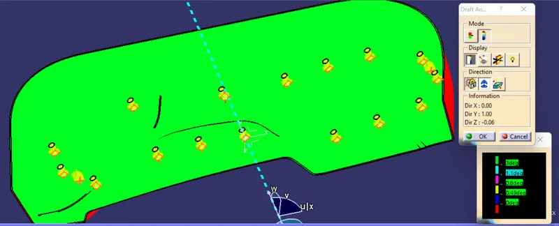
As we cab see from above image that all surfaces are clearing draft angle. Locators and Heat Stacks are clearing 0.5 degree of draft angle. So the part including Heat Stacks & locators are manufacturable.
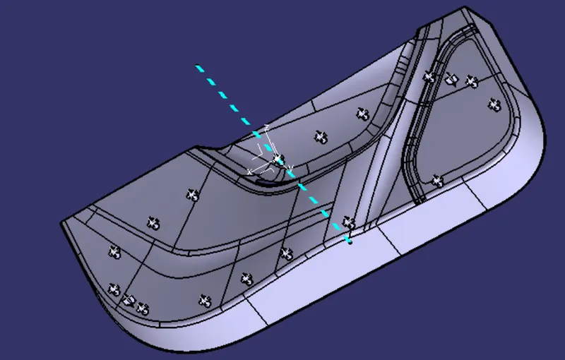
Views of Final Body-
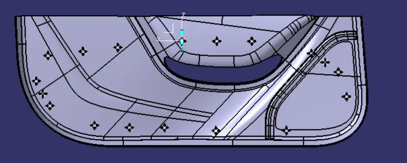
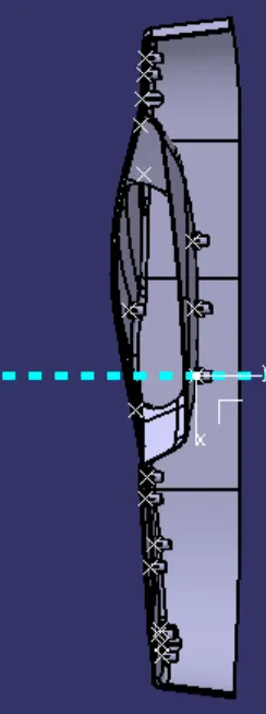
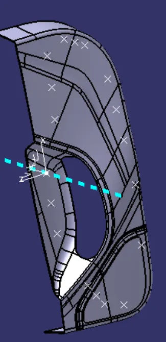
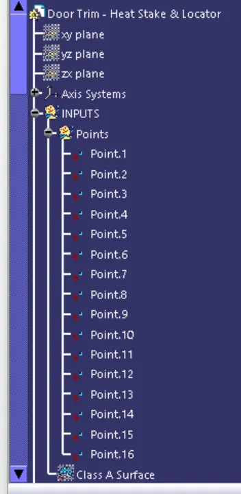
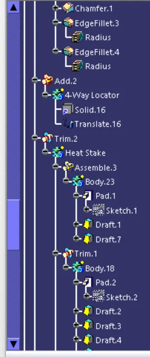
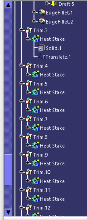
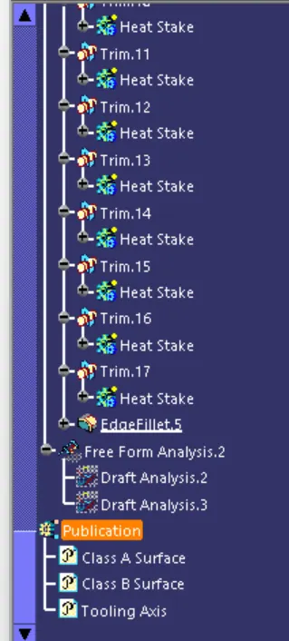
Tree structure of geometrical sets-