Week 9 - Project 1 - Door Trim Lower with Engineering Features
Aim:
To create Door Trim with Heat Stakes and Locator components from the given Class-A Surface and to perform draft analysis on the final component using CATIA V5 tool.
Objectives:
- Creation of Tooling Axis with bisecting method.
- Creation of Class B and Class C surfaces.
- Creating a solid part from the surface using close surface feature.
- Creation of Heat Stakes and Locators at the given reference points.
- Perform draft analysis of final component.
Introduction:
This project aims to create door trim with Heat Stakes and Locator using given Class A surface. The approach includes creation of Class B and Class C surfaces keeping 2.5 mm thickness in mind for the complete component. Later, create Heat Stakes and Locator at the given reference points on the B surface with respect to the given design rules
Design Constraints:
- ALTERATION OF CLASS A IS NOT ALLOWED.
- ALL SURFACES SHOULD BE CLOSED BEFORE CONVERTING TO SOLID.
- ALL FACES SHOULD MEET THE ALLOWED DRAFT REQUIREMENTS.
Procedure:
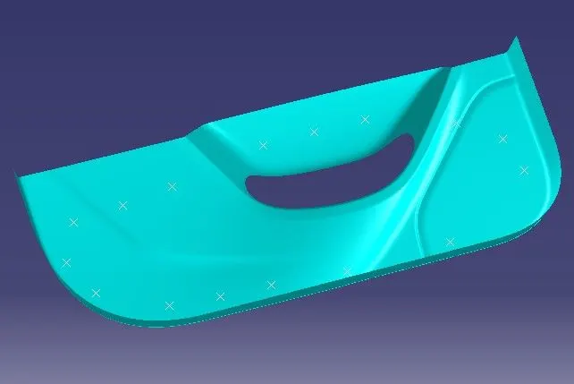
Class A surface:
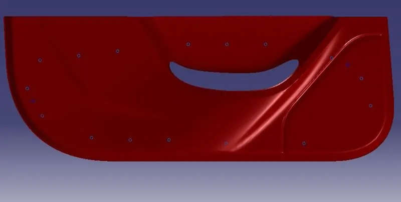
Following surface is the input for component creation.
- Class A surface is used to begin the design of a product.
- To continue with the design process, need to find out the tooling axis for surface-A.
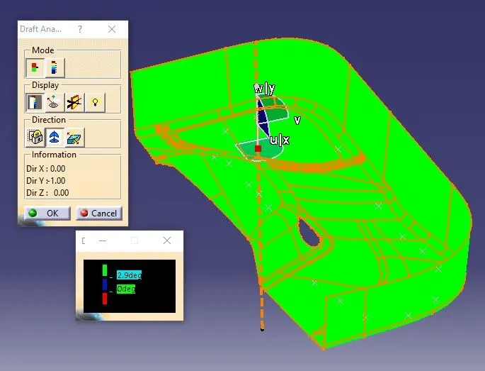
- In the next step, need to check for all the drafts using Draft Analysis tool of CATIA.
Draft Analysis for Surface A:
- The Drafting analysis is performed using the Feature Draft Analysis command from INSERT menu
- The drafting analysis is done with 2.9 degree draft angle.
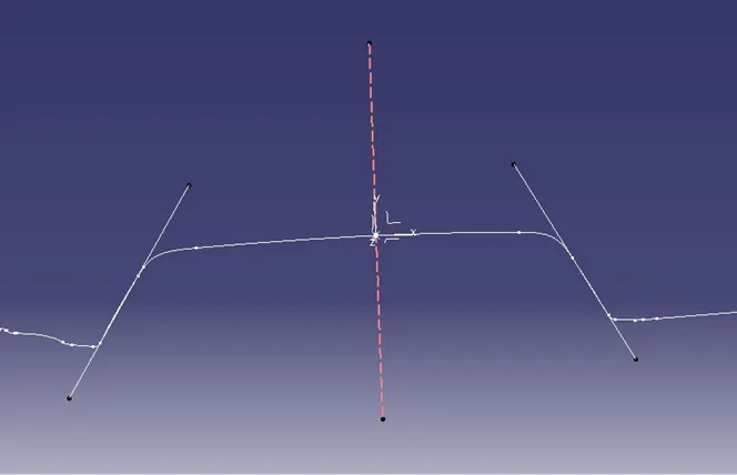
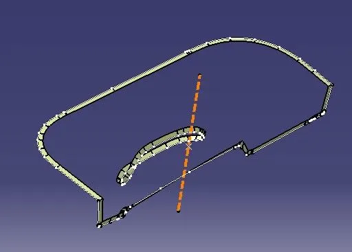
Creation of Tooling Axis:
- An axis system is created using a reference point created on the given surface.
- Create an intersection of CLASS A surface with XY plane.
- Tooling axis is created from these two lines as shown in above image using Bisecting option.
- The dashed line shown in figure is the tooling axis.
Creation of Class B surface:
- Class B surface is created from the Class A surface.
- Extract the surface from Class A and offset it with a distance of 2.5mm.
- The resultant surfaces are then trimmed to form the Class B surface.
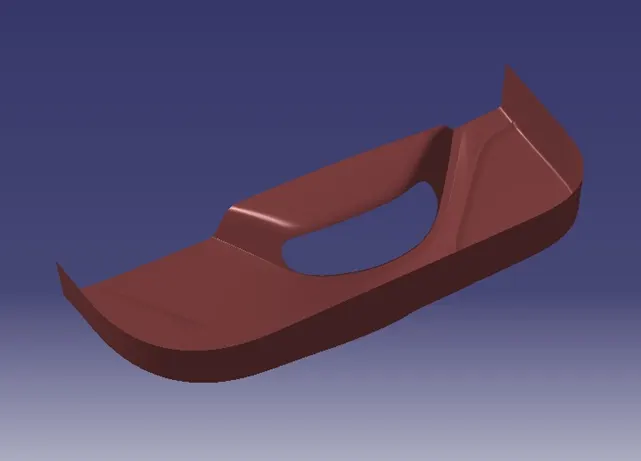
Creation of Class C surface:
- Class C surface connects the Class A and Class B surface.
- For creating Class C surface, initially the boundary of Class A is extracted using Boundary
- Then Sweep and multi section surface commands is used along the draft direction.
Class A + Class B + Class C:
- To make Class A and Class C as a single body, both surfaces are joined using Join This command is used to make sure that there is no any open boundary between Class A and Class C.
- To obtain the final output the joined Class A+C is trimmed with the Class B surface using trim feature.
- Solid body is obtained using closed surface feature from part workbench.
- The Tooling axis, Class A, B and C surfaces were published.
Creation of Heat Stakes:
Heat Stakes is a B side feature used for assembly fixation of joining two dissimilar materials together. It makes it easy to bond metal to plastic and is commonly used in high volume-low cost applications such as automotive, IT and consumer appliances. The main benefits are as follows:
- Similar and dissimilar materials may be joined: metal to metal, plastic to plastic, metal to plastic.
- Local heating resulting in no damage to surrounding materials.
- No mechanical vibration.
- Excellent durability.
- Increase efficiency
- Easy maintenance.
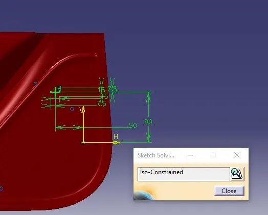
For creation of heat stakes there is no default design rules. It depends upon manufacturer. Usually, the outer diameter of heat stakes is taken as 7mm and inner diameter as 5mm.
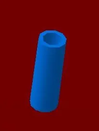
Fig:Heat Stake
Creation of Locators:
A work piece in free space have 12 degrees of freedom. These degrees of freedom must be restricted to ensure proper referencing of a work piece. The devices that restrict a work piece’s movement are the locators. The locators, therefore, must be strong enough to maintain the position of the work piece and to resist the cutting forces. It provide a positive stop for the work piece.
A 2 way locating pin restricts motion along 1 axis or2 degree of freedom. Similarly, a 4 way locator restricts 4 degree of freedom along two axis. The design rule for locator is same as of rib design.
The length of locator should be maximum 15mm.The draft angle should be 0.5 degree. It should be chamfered and provided with fillets on its edges for its smooth movement.
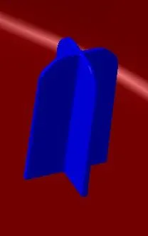
Fig:A 4-way locator
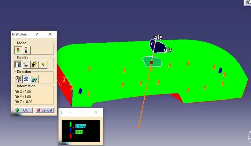
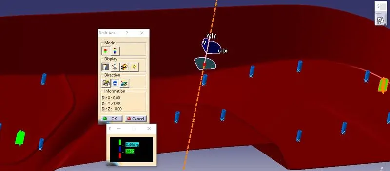
Draft Analysis of Door trim:
- Main tooling axis is taken as the draft reference for this analysis.
- The Drafting analysis is performed using the Feature Draft Analysis command from INSERT menu
- The drafting analysis is done with 0.49 degree draft angle.
Draft Analysis of Locator:
- For Locator, draft analysis is performed to ensure proper drafting with respect to main tooling axis.
- The Drafting analysis is performed using the Feature Draft Analysis command from INSERT menu.
- The drafting analysis is done with 0.49 degree draft angle.
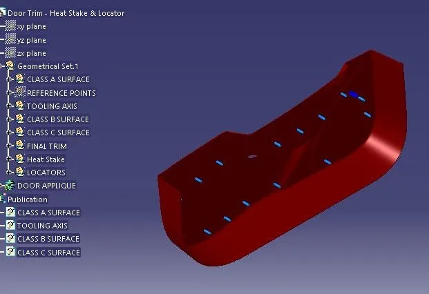
Tree Structure
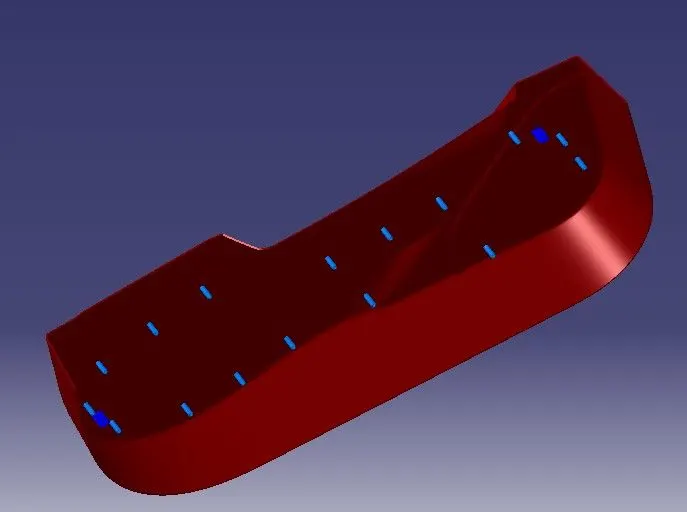
Isometric View
Front View
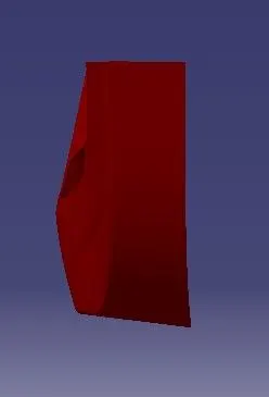
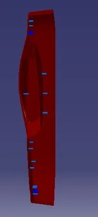
Side View
Top View
Iso-Constrained
Conclusion:
Final output “DOOR TRIM with heat stakes and locators” is successfully designed using CATIA VS tool.