Advanced Sheet Metal Design Using NX Cad Challenge_7_ Metal bracket-II
1. Title of the project
Metal bracket design using Siemens NX Cad (Student edition) application.
2. Objective
To understand the procedures used in metal bracket design using Siemens NX CAD software.
3. Introduction
NX for design is an integrated solution that helps you develop innovative new products. Unlike CAD only solutions and closed enterprise solutions delivers the highest integration between development disciplines in an open, collaborative environment. It delivers immense value to enterprises of all sizes It also mergers solid and surface modelling techniques into one powerful tool set. It provides a set of tools within NX environment that allows for simple fast and accurate design of sheet metal parts.
In mechanical engineering a bracket is any intermediate component for fixing one part to another, usually larger, part. In addition to creating a connection between two parts, a bracket may provide support. Some bracket, such as gusset brackets are designed with a diagonal section that reduce the strain on the bracket and allows it to support heavier loads This project is a step-by-step approach of sheet metal bracket design using Siemens NX CAD (student edition) software. It is prepared with the self-guiding tutorial by the Skill Lync as a part of my certification course program.
4. Design Methodology
The 3D design of sheet metal bracket design using Siemens NX CAD Student edition software. The methodology followed in the project is as follows:
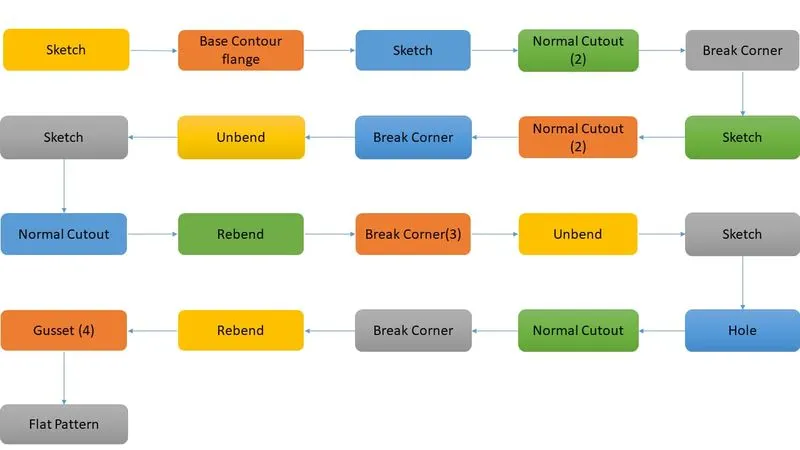
NOTE: As this project used NX CAD (Student edition) software, ADVANCED FLANGE command is not available in the application. Therefore, the particular design element is missing in the final image
5. Description
The features used in design are described below.
- Sketch
In NX, create sketch by choosing Sketch in Home toolbar. The screen will display the sketch options. You can choose the Sketch Plane, direction of sketching and type of plane for sketching. Here choose the XC-YC plane and click OK. The sketch plane will appear and the X-Y directions will be marked. This is the basic sketch window.
- Contour flange
It creates main base flange or second flange by extruding sketch in sheet metal application.
To activate command from “Menu => Insert => Bend => Contour Flange”
- Normal Cutout
This command is used to extract volumes from sheet metal by using sheet metal production principles. Cutting faces will be perpendicular to the sheet metal surface.
To activate the command “Home => Feature Group => Normal Cutout”
- Break corner
This tool is used to rounds a sharp corner of a tab or flange. It completely formed with radius and created smooth edges
- Unbend
This command is used to flatten the bend and material adjacent to the bend. The path or the command is as follow “Menu => Insert => Form=> Unbend”
- Rebend
This command is used to restores an unbend feature to its previous state along with any feature added after the unbend feature. To use this command from “Menu => Insert => Form=> Rebend”
- Bead
This tool is used to lift material along the contour of the sketch that stimulates a stamping tool. Its available from punch group gallery in NX
- Hole
This command is just like to put holes in the sheet metal with respect to measurement. With hole command, you can make: General holes, Drill holes, Screw holes etc. To find this command from home tab: Feature group->Hole
- Gusset
Gussets are stiffening features created across a bend to reinforce the sheet metal part. To activate the command, Click Home > Punch > Gusset and click on a bend face
- Flat pattern
This command is used to create a flat pattern feature from the formed sheet metal part. The command can be selected from flat pattern group from home tab.
The following are different views of the sheet metal odd shape enclosure.
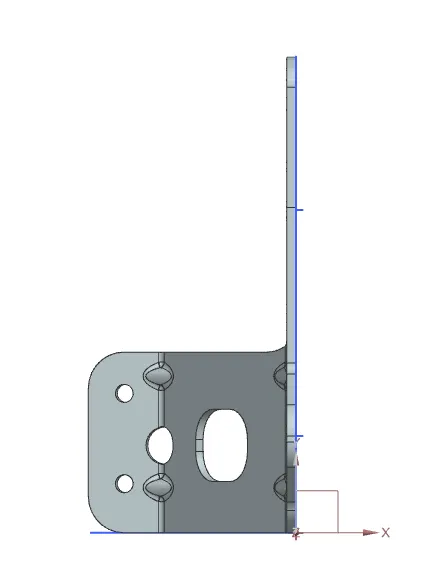
Figure1: Top View
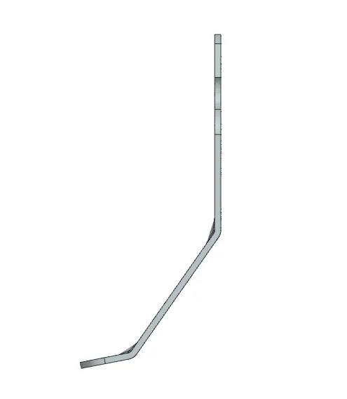
Figure2: Front View
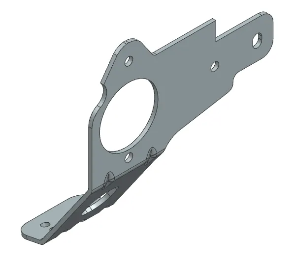
Figure3: Isometric View
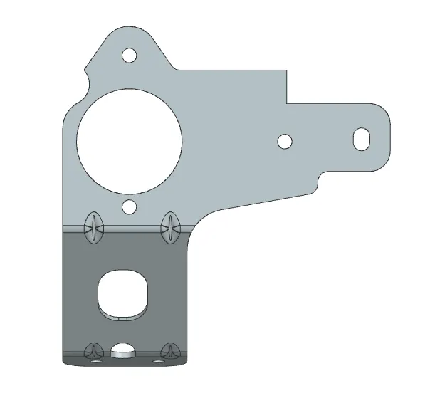
Figure4: Right View
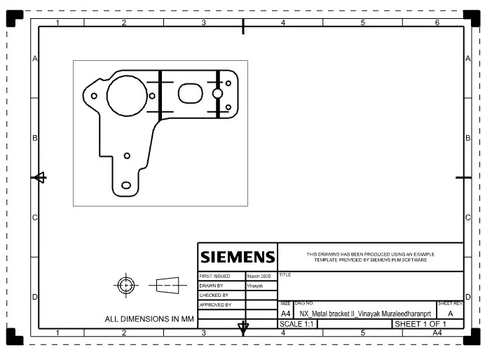
Figure5: Drawing Sheet Image
6. Conclusion
This project shows as an example of how NX CAD can be for used to create a metal bracket design by using various different features as per requirement of the designer.