Advanced Sheet Metal Design Using NX Cad Challenge_2_Box Assembly
1. Title of the project
Sheetmetal box assembly using Siemens NX Cad Sheetmetal application.
2. Objective
To understand the procedures used in sheet metal box assembly using Siemens NX CAD software.
3. Introduction
NX is one of the world’s most advanced and tightly integrated CAD/CAM/CAE product development solution. The NX software integrated knowledge-based principles, industrial design, geometric modelling, advanced analysis, graphics simulation and concurrent engineering. It has powerful hybrid modelling capabilities by integrating constraint-based feature modelling and explicit geometric modelling. It allows the user to design complex free-form shapes such as air foils and manifolds. It also mergers solid and surface modelling techniques into one powerful tool set.
This project is a step-by-step approach of sheet metal box assembly using Siemens NX CAD (student edition) software. It is prepared with the self-guiding tutorial by the Skill Lync as a part of my certification course program.
4. Design Methodology
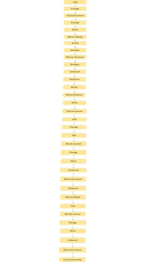
The 3D design of sheet metal box and assembly is done using Siemens NX CAD Students edition software. The methodology followed in the project is as follows:
5. Description
The features used in design are described below.
- Sketch
In NX, create sketch by choosing Sketch in Home toolbar. The screen will display the sketch options. You can choose the Sketch Plane, direction of sketching and type of plane for sketching. Here choose the XC-YC plane and click OK. The sketch plane will appear and the X-Y directions will be marked. This is the basic sketch window.
- Tab
It creates a base feature by extruding a sketch along a vector by a thickness value or add material to a planar face. Additional planar selections can be added to generate bends as a part of the base feature.
- Flange
This tool is to adds a flat flange at an angle to a planar face and adds a bend between the two.
- Dimple
This tool is to lifts an area of the model inside a sketch that simulated a stamping tool.
- Mirror body
This tool is used to copies a body and mirrors it across a plane
- Unbend
This tool is to flattens a bend and the material adjacent to the bend.
- Rebend
It restores an unbend feature to its previous bent state, along with any features added after the unbend feature.
- Bead
It lifts material along the contour of a sketch that simulated a stamping tool.
- Mirror feature
It copies a feature and mirrors it across a plane
- Break Corners
This tool is to chamfers a sharp corner of a tab or flange.
- Hem
This tool is used to folds the edge of a sheet metal flange over onto itself for the purpose of safe handling or to increase edge stiffness.
- Normal Cut out
This tool is to cuts material by projecting a sketch onto the model and then cutting perpendicular to the faces intersected by the projection.
The following are different views of the sheet metal box.
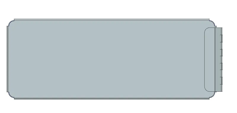
Figure1: Top View
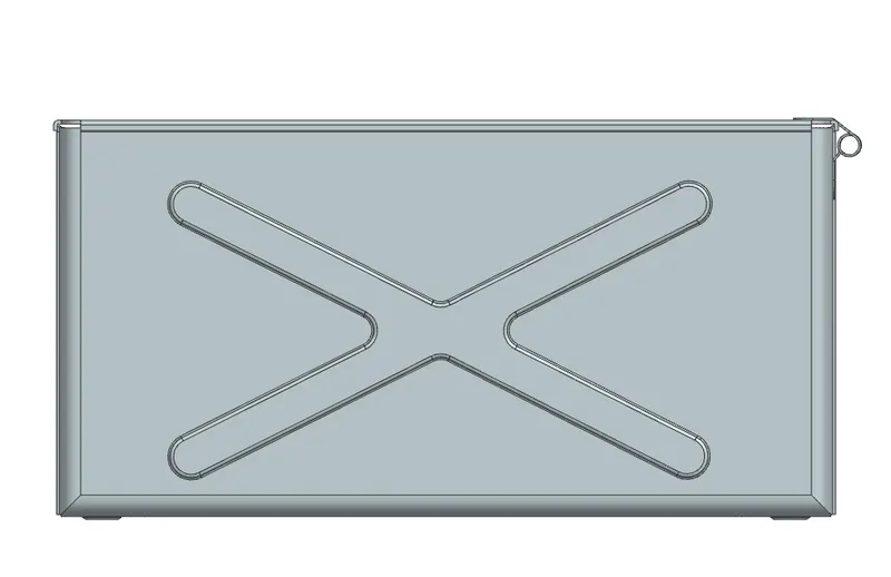
Figure2: Front View
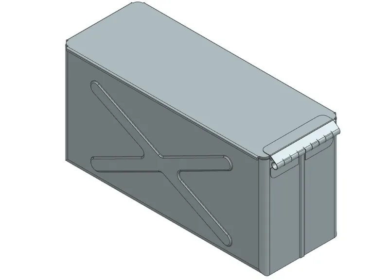
Figure3: Isometric View
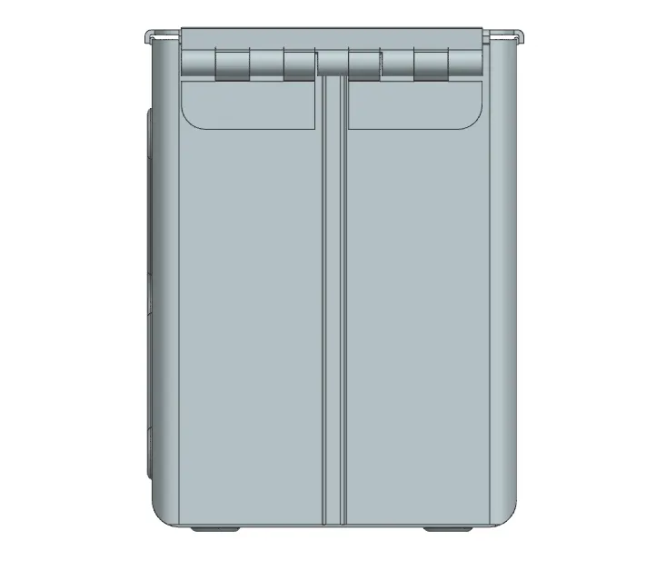
Figure4: Right View
6. Conclusion
This project shows as an example of how NX CAD can be for used to create a 3D design by creating parametric assemblies and models that can then be easily made into several iterations. An extra advantage is the possibility of many designs variant testing which allows improving the design constructional process.