Week 9 - Project 1 - Door Trim Lower with Engineering Features
AIM
To study the creation of locator and heat stakes.
OBJECTIVE
Create the Door Trim Lower Plastic component through the given Class-A surface. To begin with, the tooling axis for the given Class-A Surface should be created meeting the requirements of the draft angle and at the end perform the Draft analysis on the model.
THEORY
Heat Stakes design :-
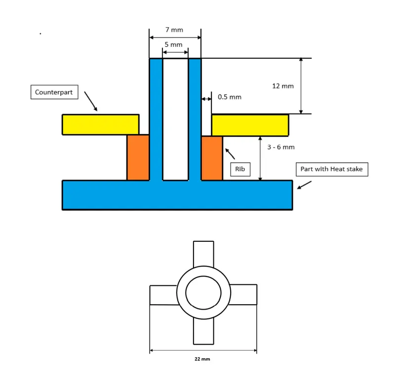
figure 1. heat stakes design
- Counter Part Thickness - Will be given as input
- Component Wall Thickness - Will be given as input
- Length of the Rib - 22 mm
- Height of the Ribs - 3 mm to 6 mm
- Inner Diameter of Heat Stake (d) - 5 mm
- Outer Diameter of Heat Stake (d) - 7 mm
- Minimum clearance between heat stake and counterpart - 0.5 mm
- Height of the Heat stake - Depends on the rib height and counter-part thickness
- Minimum fillet of Heat Stakes - 0.25 mm
- Minimum Draft Angle of Heat Stakes - 0.5 degrees
Locator :-
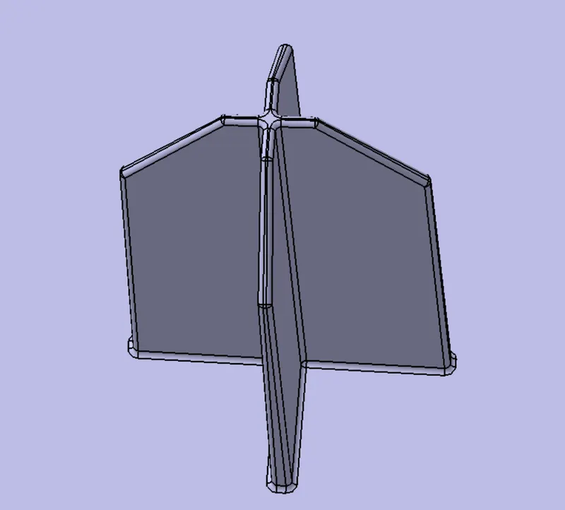
figure 2. four way locator
- Height of the locators should be 1 mm (or) 2 mm greater than the heat stakes
- Thickness, fillet and draft angle are of same as rib design rules.
- Ideal Chamfer value - 5 mm x 45 degrees
- Ideal length of the locators - 15 mm
TOOLING AXIS
Here the tooling axis is created parallel to the Y axis because in this direction we can see the whole surface and surface is not planar. That is create the point on surface and create a line at that point using point and direciton option. Where as direction as XZ plane. Bisecting line method for creating a tooling axis is suitable for symmetric surfaces.
DRAFT ANALYSIS OF CLASS A SURFACE
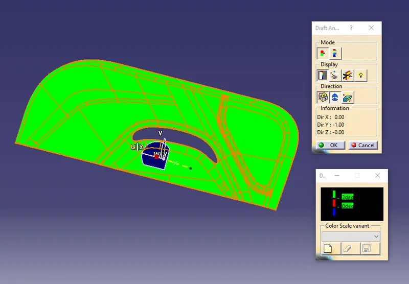
figure 3. class A draft analysis
Here draft analysis carried for class A surface with respect to tooling axis. Here colour code used is a green colour indicating that the draft is 3 degree or above. The red colour indicates that the draft is 0 degree and the blue colour indicates that the draft is minus value. From draft analysis we can see that green colour is all over the surface and hence it is suitable for further process because it follows optimum draft.
DRAFT ANALYSIS OF A MODEL
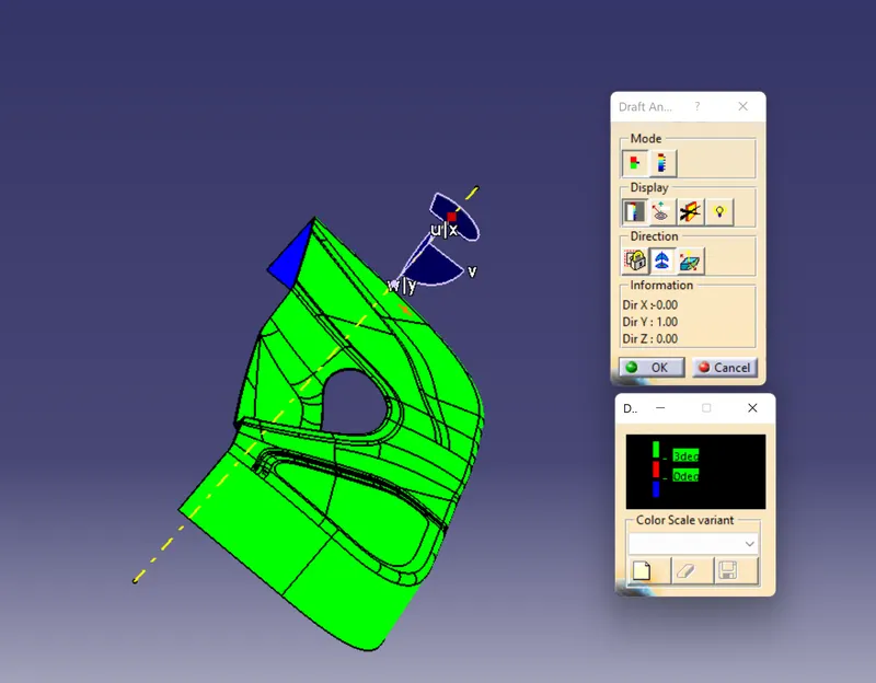
figure 4. door trim draft analysis
Here we need to check the draft of door trim, locator and heat stakes along tooling axis. First check the for the door trim, we have to set colour for the draft analysis with minimum draft of 3 degrees. Here colour code used is a green colour indicating that the draft is 3 degree or above. The red colour indicates that the draft is 0 degree and the blue colour indicates that the draft is minus value. From draft analysis we can see that green color over the surface of the door trim. That is the door trim follows optimum draft of 3 degrees.
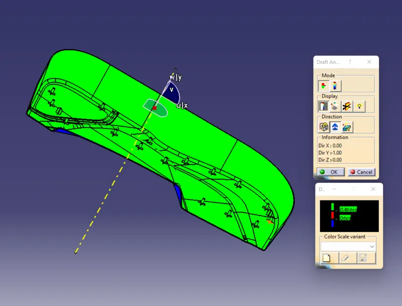
figure 5. draft analysis with 0.48 degrees
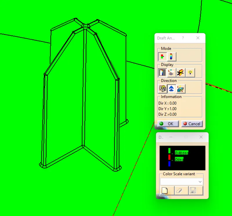
figure 7. draft analysis of locator with 0.48 degrees
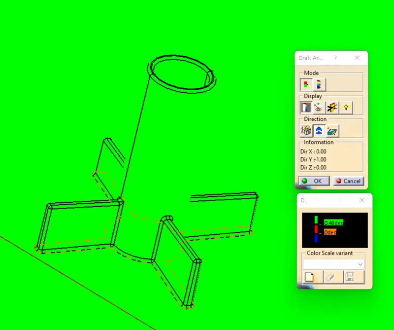
figure 8. draft analysis of heat stakes with 0.48 degrees.
Next we have to check the draft of locator and heat stakes along tooling axis. Then set the colour code for the draft analysis with minimum draft of 0.48. Here colour code used is a green colour indicating that the draft is 0.48 degree or above. The red colour indicates that the draft is 0 degree and the blue colour indicates that the draft is minus value. From draft analysis we can see that green colour over the surface of the locator and heat stakes. That is the locator and heat stakes follows optimum draft of 0.48 degrees.
MODEL VIEWS
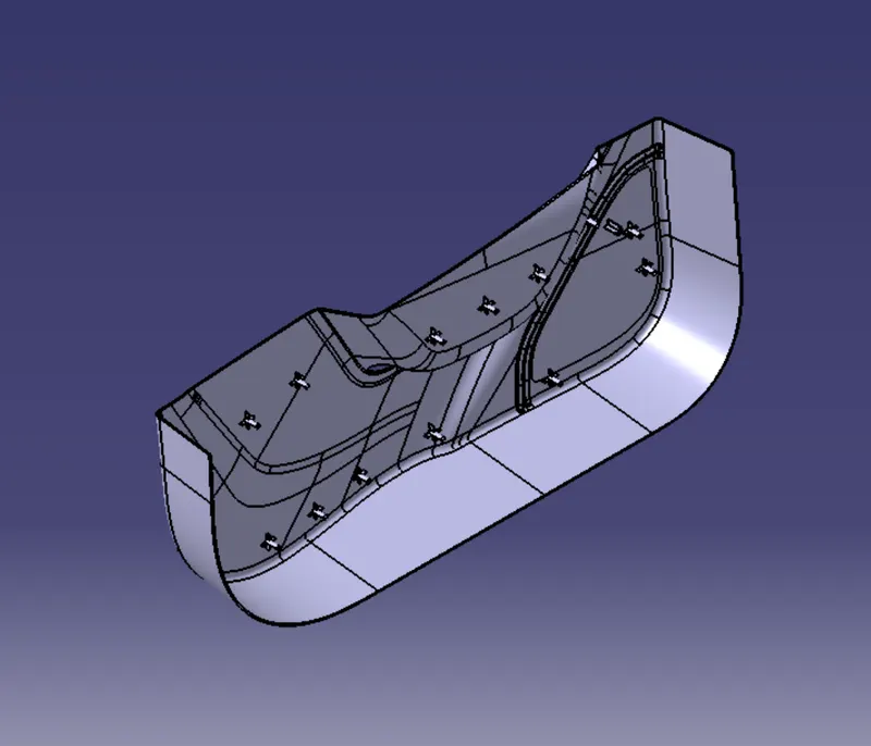
figure 9. isometric views
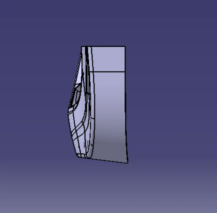
figure 10. front view
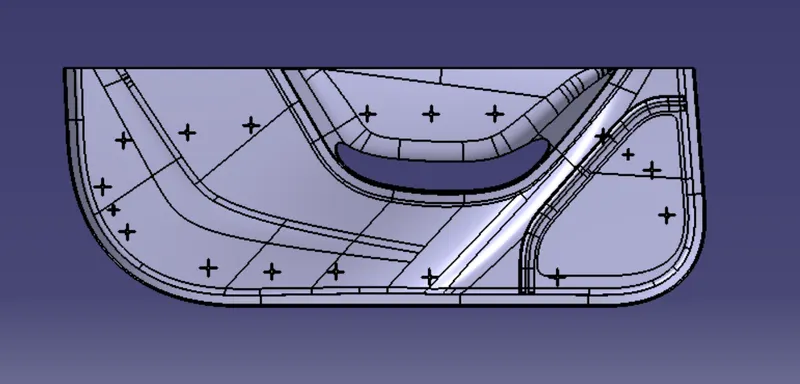
figure 11. right side view
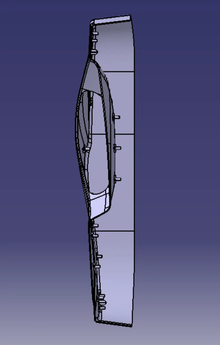
figure 12. top view
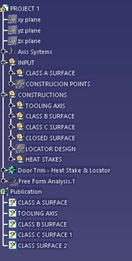
figure 13. tree structure
CONCLUSION
Creation of locator and heat stakes are studied.