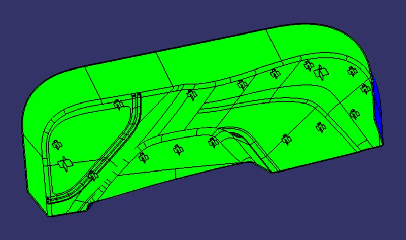
Week 9 - Project 1 - Door Trim Lower with Engineering Features
AIM :
Create the Door Trim Lower Plastic component through the given Class-A surface. To begin with, the tooling axis for the given Class-A Surface should be created meeting the requirements of the draft angle and at the end perform the Draft analysis on the model.
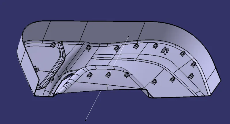
Create the Heat Stakes and the locators considering the design rules mentioned in the video for the door applique.
Introduction :- Door Trim is made from the plastic and this component is made by plastic molding process. And this is designed with the help of CATIA V5 software. Because it comes under surface design and CATIA is best to perform surface design and draft analysis. It has more accuracy than other.
Consider the thickness of the component 2.5 mm.
Tooling Axis :-
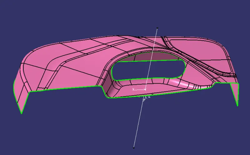
Tooling axis or tooling direction is main consideration for plastic part and mold parts because it defines movement of mold part and possibility of plastic part to come-out from mold part (Core and Cavity). In Molding machine arrangement is given to open the mold along a direction which is known as Tooling Direction. The mold is built from two separate halves (Core and Cavity) and tooling direction basically define the direction of mold pulls apart. Tooling direction is known as primary direction.
- Here I create a tooling axis. First I extract a plane then I create simple draft analysis for detecting purpose that through which teper surface is need to draw line. Then I find this 2 taper surface where I drawn 2 lines.
Draft Analysis :-
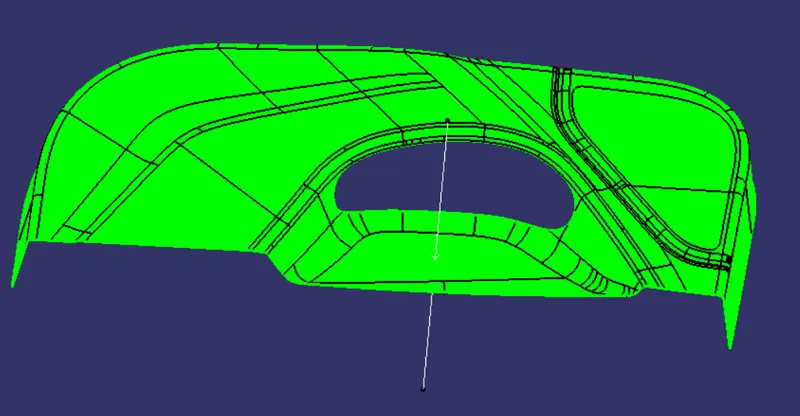
The Draft Analysis allows the user to easily analyze a part for proper draft angle. A Draft Angle describes the amount of taper for molded or cast parts perpendicular to the parting line. Draft Analysis is applicable for 3D part models. To create a draft analysis for any 3D part file, the user needs to select part/surface and select the pull direction. You can change the pull direction.
Draft Analysis of Class A Surface In CATIA :- It provides colour based identification. With the help of this we can easily find that which surface is in clear and which is in stuck by colour changing. Here I give the draft angle 3 degree. The result in colour based that the surface which green (means draft angle > 3 degree) is right. And where the colour is blue mean draft angle is 3 degree to 0 degree if this surface area is low then you can go. If you find red colour zone then it means draft angle is less than 0 degree. Then you will have to create tooling axis by another way if possible, otherwise you can say your design engineer to correct for designing.
CLASS A
What is meant by Class A :
- The Class A technique is used to design automobiles, high-end products like mobile phones, and aerospace craft, where the shapes must be of the highest quality. This course introduces the concepts behind Class A surfacing, including an explanation of key terms and their roots in shipbuilding history. You also learn the fundamentals of Class A surfacing design—from deriving curves to creating mesh surfaces—and find out how to implement these techniques in CATIA V5, a leading CAD platform.
- It's basically everything that you see and touch or engage with inside of a car, outside of a car, inside of your home. Whether it's furniture or on an airplane. Something that's been stylized to meet a certain requirement. Maybe you want a car to look like it's going fast while it's sitting still. Maybe you want something to look big and strong and bulky or something soft and a little bit more tender to the world. It's the emotional connection that the stylist has that is brought to the real world by a digital sculptor. The digital sculptor takes these inputs from the stylist and creates these surfaces to meet the requirements not only of the stylist but also for engineering and manufacturing purposes. It is the connection of art to the real world.
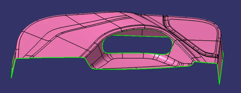
- Class A surface models are called digital sculptors
- The class A surface represents the absoulte peak of styling for freefrom surfaces.
- Class A is a term used in specifically in Autommotive Design.
- It describes the final production surface data for the aesthentic parts of the car.
PROCEDURE:
- First we can take the catpart or Stepfile.
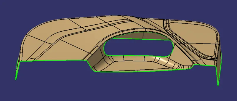
- Now we need to check the surface with the help of boundary wheather it has any open boundary or not .
- Now we want to check the draft analysis for the class A.
CLASS B
- The Class B finish is a quality finish with only minimal imperfections. A Class B finish is the most common finish for exterior surfaces. It is normally specified on surfaces such as external covers, panels, and parts that are fairly prominent.
- .B surface means thickness of a part it is not visible it is inside part.
- Class B finish concrete surfaces with plywood, metal, metal- framed plywood faced or other acceptable panel-type materials, to provide continuous, straight, smooth, exposed surfaces.
- The Class B finish is a quality finish with only minimal imperfections. A Class B finish is the most common finish for exterior surfaces. It is normally specified on surfaces such as external covers, panels, and parts that are fairly prominent.
CLASS C
- The Class C finish allows more imperfections than Class A or B. Class C is often specified for interior surfaces not readily visible, surfaces that will be covered by another part when assembled, or surfaces which the Customer feels do not need to meet a high cosmetic finish.
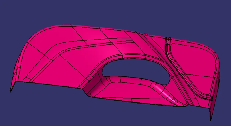
FINAL TRIM:
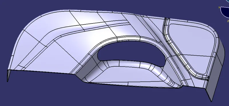
CLOSED BODYSURFACE:
VIEWS OF BODY:
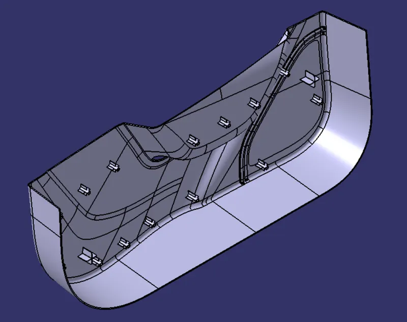
ISO METRIC VIEW:
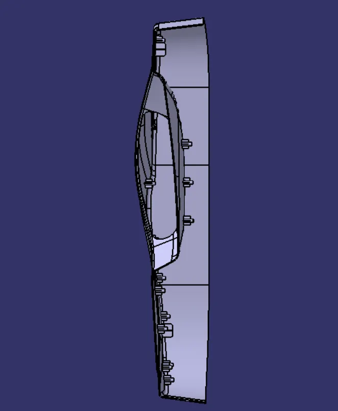
TOP VIEW:
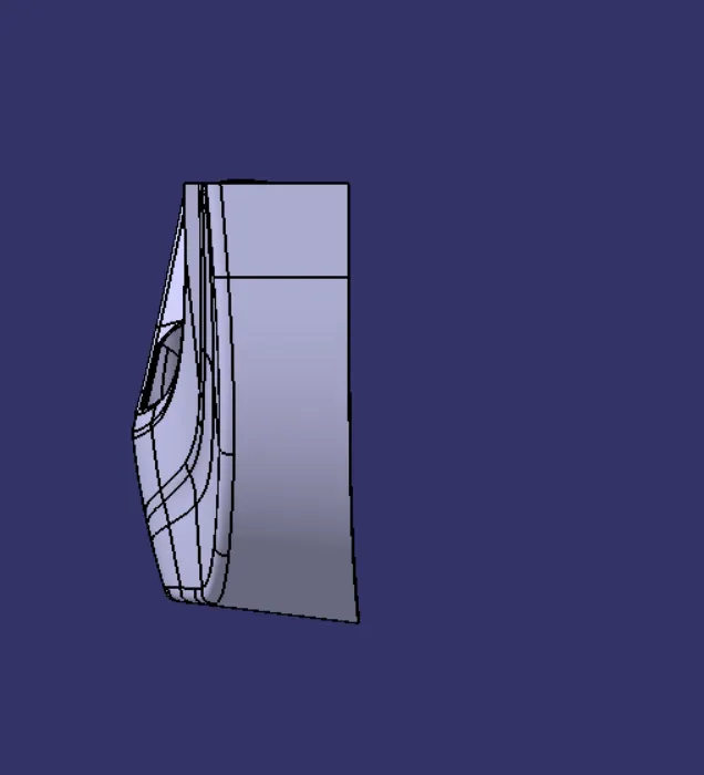
FRONT VIEW:
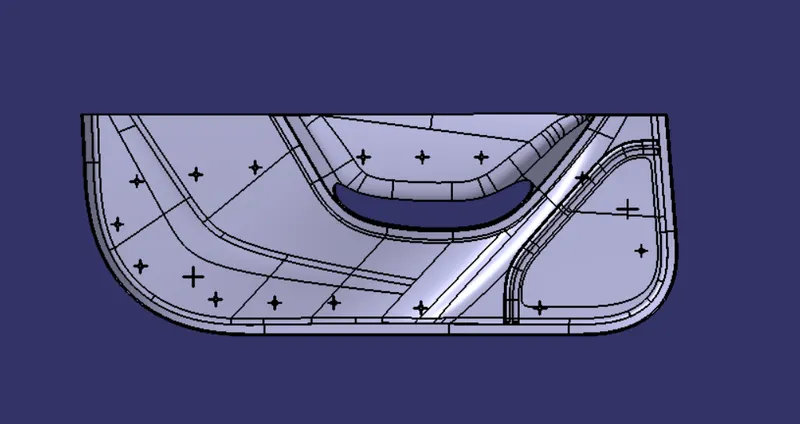
RIGHT SIDE VIEW:
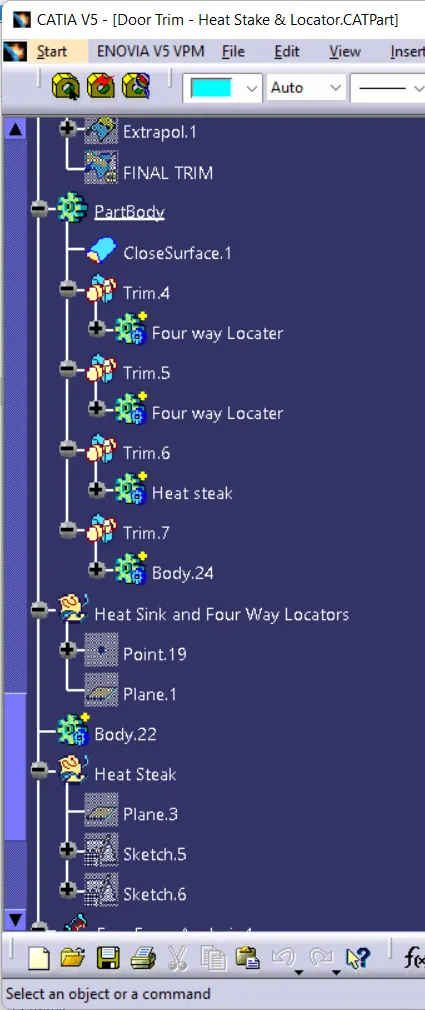
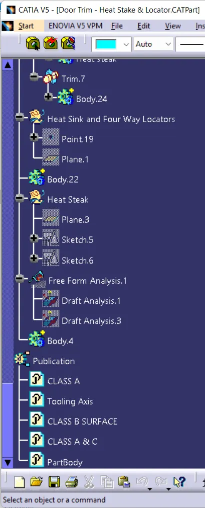
GEOMETRICAL SET TREE:
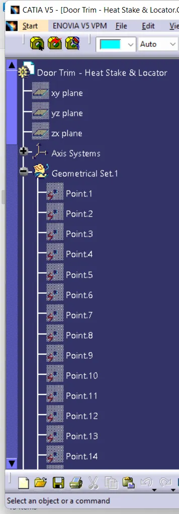
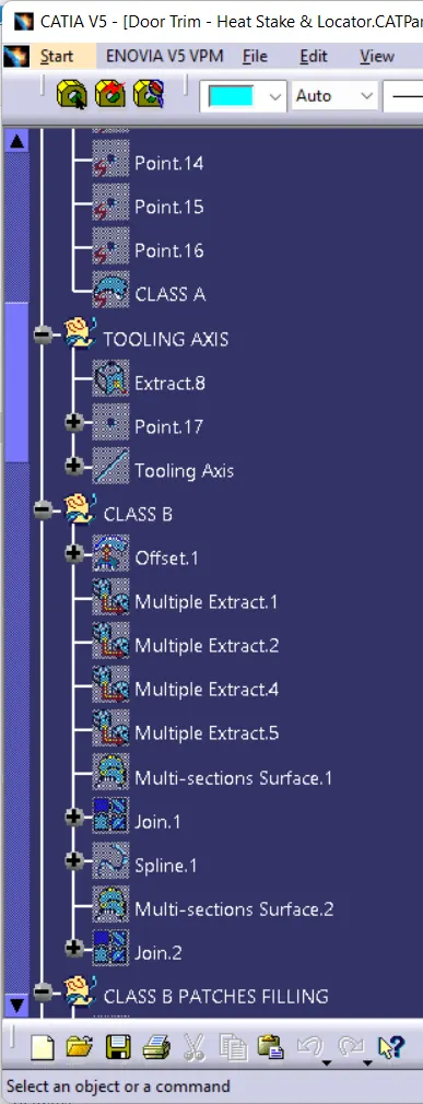
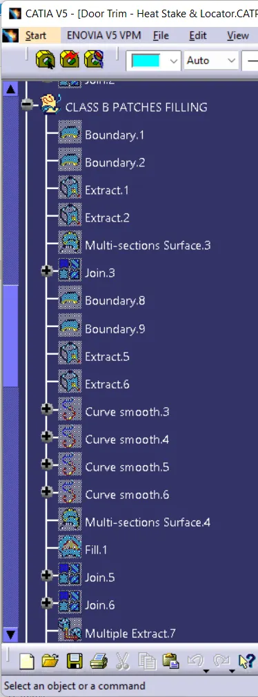
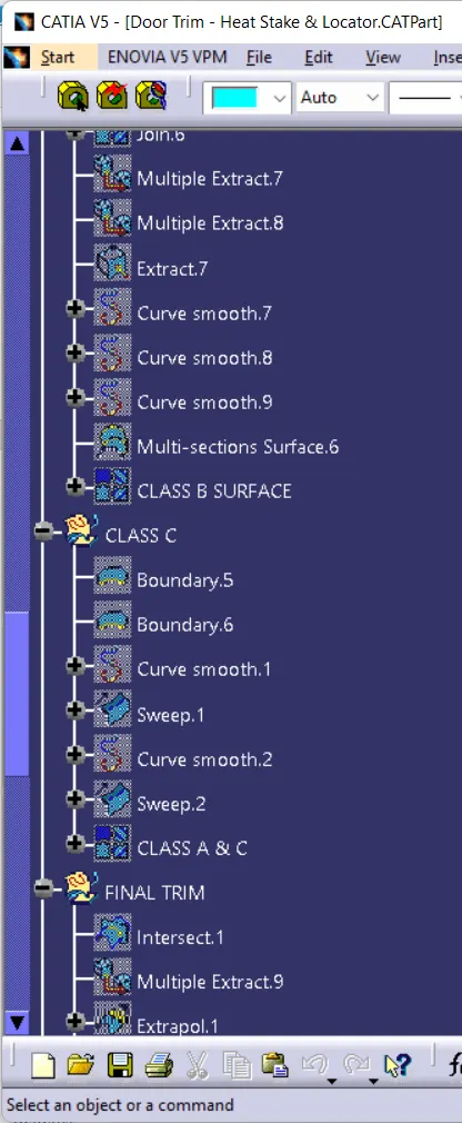
FINAL DRAFT ANALYSIS: