Week 9 - Project 1 - Door Trim Lower with Engineering Features
DOOR APPLIQUE
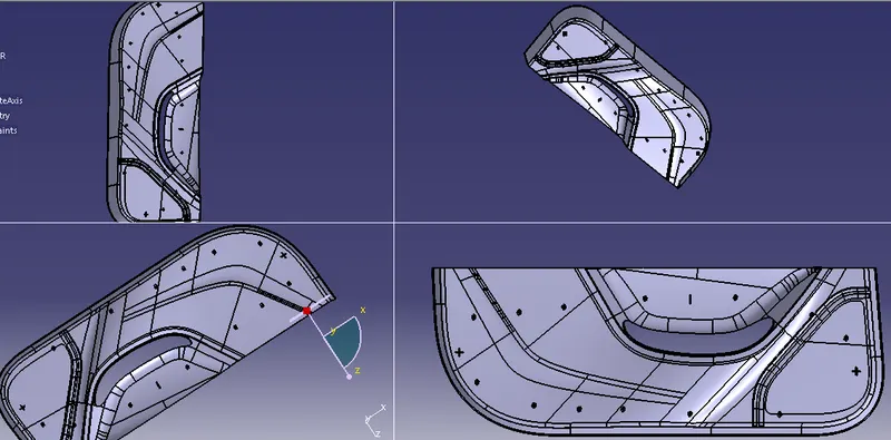
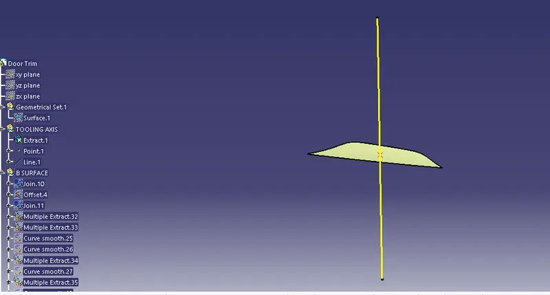
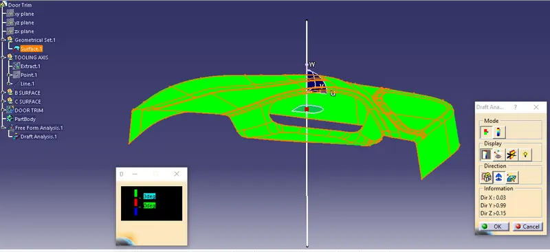
Creation of Tooling axis: By considering the given class a surface.The tooling axis direction have been decided by analysing at different views,finally the satisfying surface has been extracted and the point has been created to form a line (so called tooling axis) in a decided direction.And then the draft analysis has been performed for the class A surface to check the possibilities of other ways.But the decided tooling axis is free from draft analysis and it has been named as tooling axis for the respective class A surface.The following images will show the step by step creating and the report of draft analysis on class A surface.
CREATION OF B SURFACE
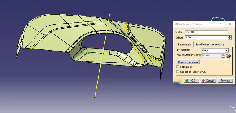
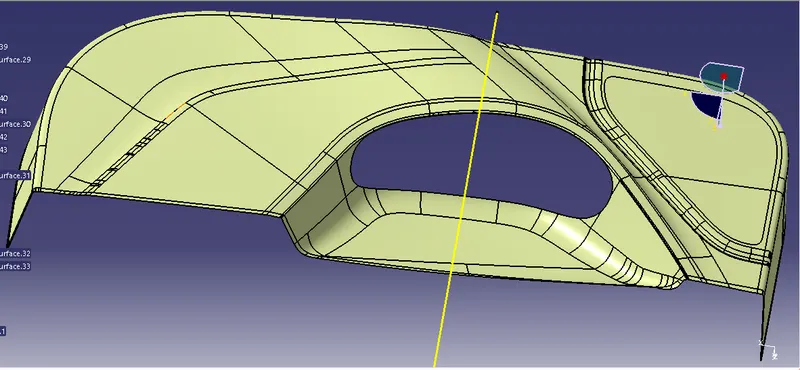
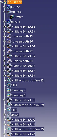
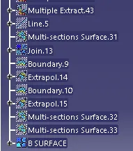
Initially the class A surface has been examined for the boundary conditions and then the same has been offsetted below for 2.5 mm , with the leaving erroneous edges the surface has been offsetted successfully, then the left out edges has been manually formed with the help of multisection tool and the fill option.Then the edge has been extrapolated by considering the surface to trim with class C and class A in future.The below pictures will show it step by step,
CREATION OF CLASS C SURFACE
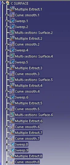
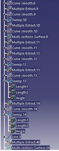
To create class C surface, by considering the class A surface and by using the sweep tool a bridge has been constructed with the required draft angle to connect class A and class B together.In few places where fillets are there on class A surface,multisection tool is used to connect on betweeen the sweeps.The below images will picturize the same:
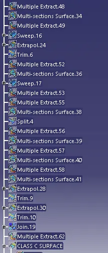
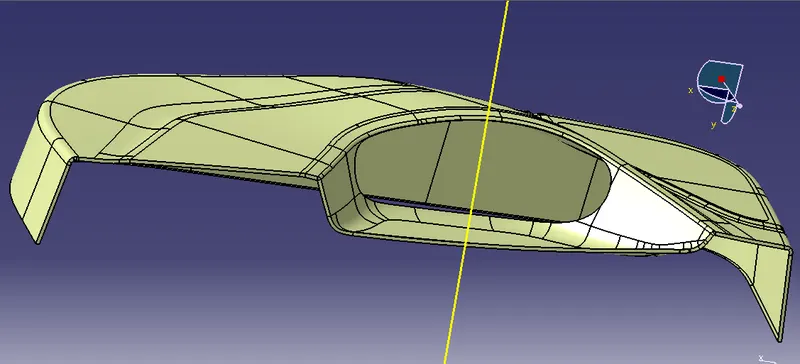
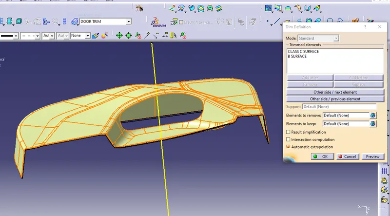
Then the joined class C and class A surface which was shown above is trimmed with the previously created class B surface to get the final output which as shown below:
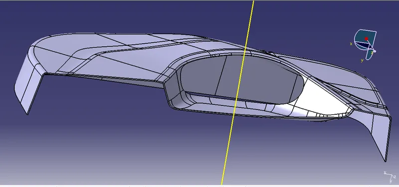
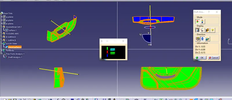
Then the surface has to be closed to form solid.So a new body has been inserted and then with the part design work bench , by using closed surface tool the required solid has been formed.Then the draft analysis has been done on the final solid model, the report and the process has shown below with following images:
CREATION OF 4 WAY LOCATORS:
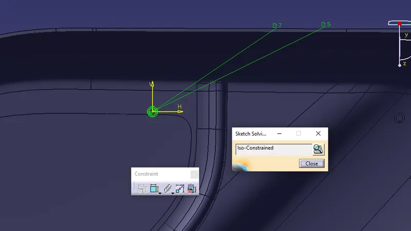
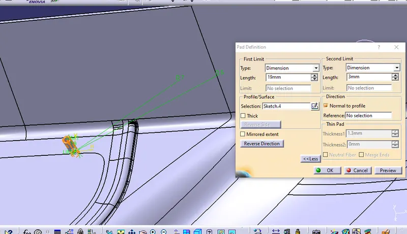
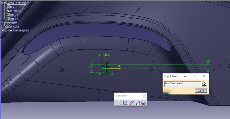
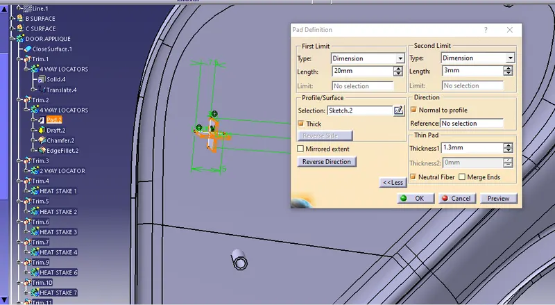
The locators are the most primary engineering feature when it comes to the the assembly section of any automobile.Since the locators are the first feature which mates with the decided part to get assembled.There are 4 way locators and 2 way locators,based on 3-2-1 fprmulae of assembly.It will be placed at the required position by considering some engineering principles.Here in this door applique part,two 4 way locators are placed one at each end where there will be maximum distance between them.Intiallly a positioned sketch has been drawn for 4 way locators then it has been padded based on the part thickness and the required entry chamfers,draft and the fillet has been provided to the four way locators.Then it has been copy and translated to the other end .
CREATION OF 2 WAY LOCATORS:
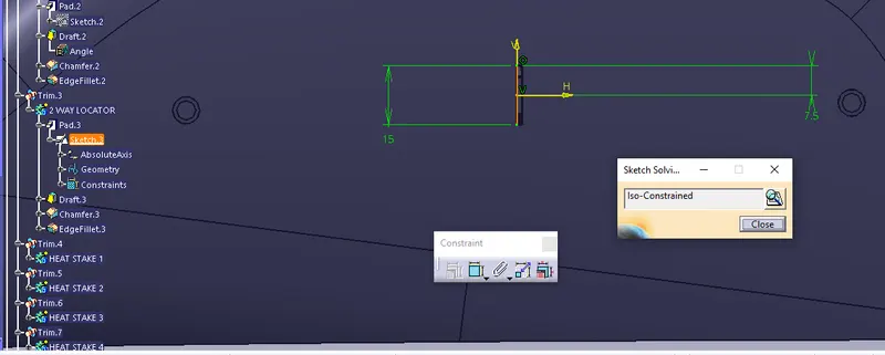
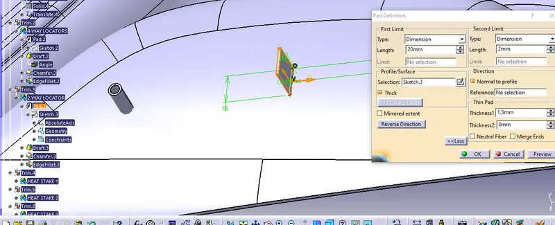
As explained above,a positioned sketch has been drawn for 2 way locators and then drafted followed with entry chamfers and fillet,then added to the main body.
HEAT STAKES:
Heat Staking is a joining technology to join two or more parts together where at least one is made out of plastic. The process is used to melt and deform the plastic material using heat and force at a set process time.Here a positioned sketch has been drawn for the heat stakes ,padded and translated to the required points by considering the minimum distance between each heat stake will be 50mm and then assembled to the main part.