Week 9 - Project 1 - Door Applique Design with Engineering Features
Objective:
- Creating the door applique plastic component through given class A surface
- Performing draft analysis on the given class A surface and on the final model
- Creating the Heat Stakes and the locators considering the design rules
Step1: Performing draft analysis on the given class A surface
- Create a point at the centre of the surface
- By using line command create a line in Y direction which will be the main tooling axis
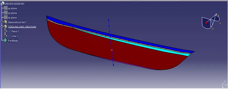
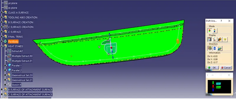
- Now perform the draft analysis on the given class A surface
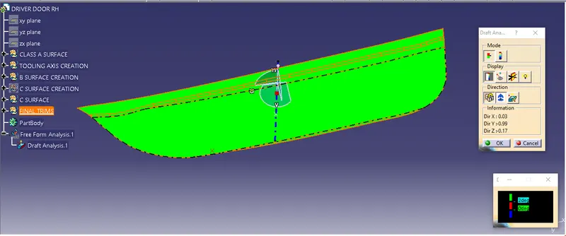
From the above image it is observed that the selected tooling axis is perfect as the surface is in green colour.
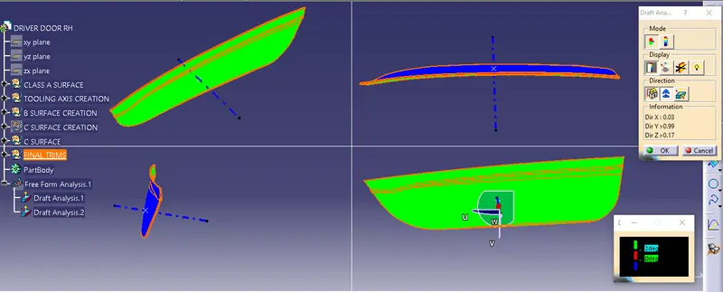
Step 2: Creation of class B surface of door applique
- Extract the class A surface, untrim it and then offset the untrimmed surface to a distance of 2.5 mm.
- Next combination of two commands trim and extrapolate are used to get the final Class B surface.
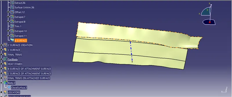
Step 3: Creation of C surface
- Extract the boundary of class A surface and use the sweep with draft direction command to get the C surface
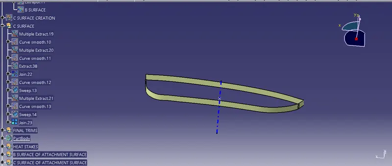
Step 4: Creation of the model
- After creation of C surface, join the class A surface with class C surface. Trim this surface with B surface to get the final model
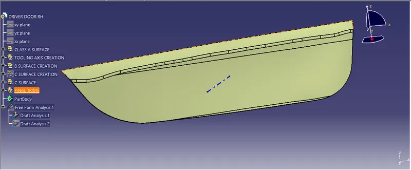
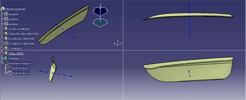
- In part design workbench, fill this surface model to get solid model using close surface command.
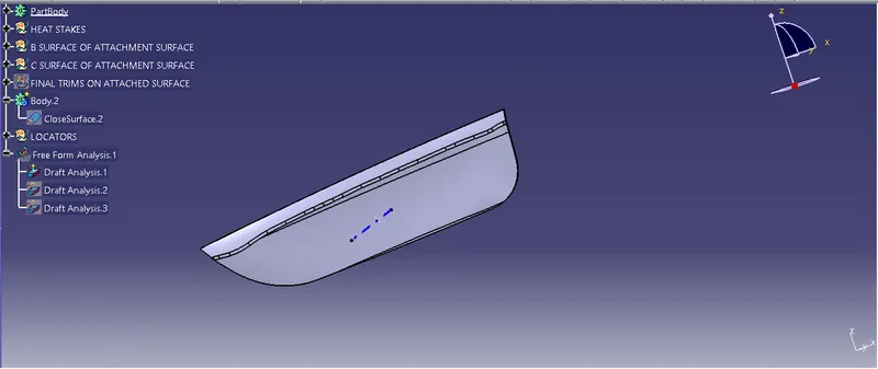
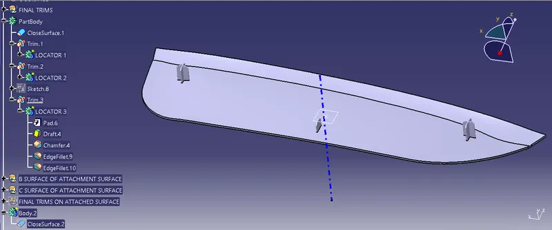
Step 5: Adding locators to door applique
- Create a point and a plane on the B surface of door applique
- Enter the Sketcher work bench and then draw the locators
- In the part design work bench, Pad the sketch, use neutral fibre command to align it properly.
- Creat entry chamfers and then fillet the edges. Before that add the draft angle to all the surfaces.
- Finally perform the boolean opeartion Untrim to get the model
Step 6: Creation of heat stakes
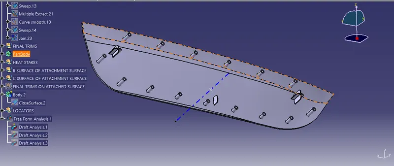
- Extract the Class B surface which will be the support surface.
- Extract the outer edges of the model using Multiple extract command. Get the parallel curve using Parallel curve command
- Use the Points and Planes repetition command to get the points on the parallel curve.
- Now create the sketch on the point created on parallel curve.
- Pad it, Add draft to it. finally perform boolean operation on the model
Step 7: Draft analysis on final model
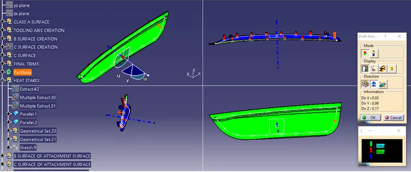
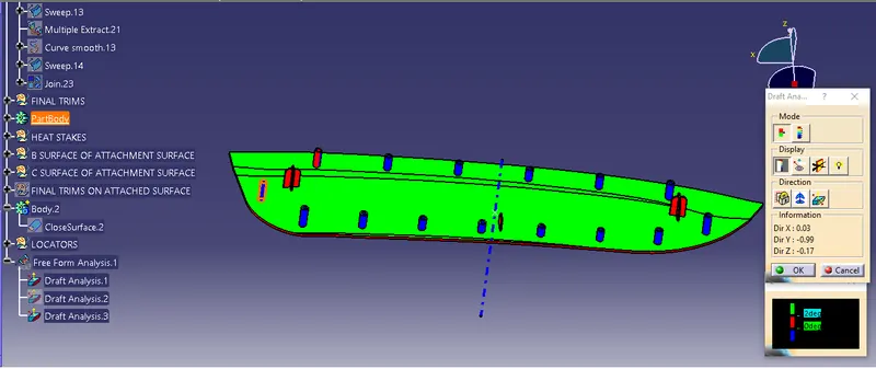
- Observation: Locators surfaces are observed in red colour indicating draft angle close to zero
- Observation: Heat stakes surfaces are in blue color, indicating negative draft angle, corrective action need to taken by providing proper draft angle.
Result
From the given class A surface
- Surface model and solid model are generated
- Engineering features are added to it
- Draft analysis is generated