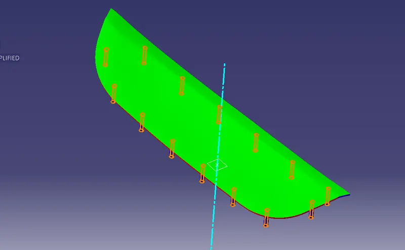
Week 9 - Project 1 - Door Applique Design with Engineering Features
Aim-
Door Applique Design with Engineering Features and Draft Analysis with the help of class A surface.
Create the Base Bracket Plastic component through the given Class-A surface. To begin with, the tooling axis for the given Class-A Surface should be created meeting the requirements of the draft angle and at the end perform the Draft analysis on the model.
Create the Heat Stakes and the locators considering the design rules mentioned in the video for the door applique.

INTRODUCTION:
A car door applique is used in the door panel to provide an aesthetic look to the door panel. There are various engineering
features in the plastic part. As we know most of the plastic parts used in the Automobiles are developed from injection molding,
we need to design the plastic parts for injection molding. There are a lot of defects that can occur in plastic part manufacturingand, we need to consider the possible defects and design the part. . Using of various B side feature that can reducesed the defect in plastic and provide strength also as dog house , four way locator etc.
SOFTWARE USED: CATIA V5
GIVEN: A- Surface of the applique and the reference body.
Procedure
DESIGN METHODOLOGY
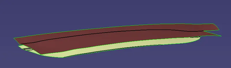
A_surface cleanup: We need to check the quality of the given A-surface. Since I got the file in IGES format we need to
disassemble it and then join it with the merging distance of 0.001 mm. Now we check the file for any error elements. We
check the surface with the BOUNDARY command to look for openings on the surface.
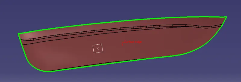
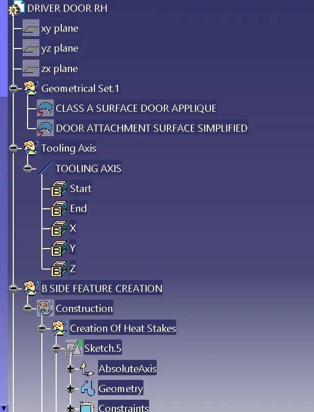
Create tooling Main tooling axis
In this part takes a point in surface and create a line with help of line command . So create a temporary axis in y axis
direction with help of of point on surface.This axis is temporary tooling axis.
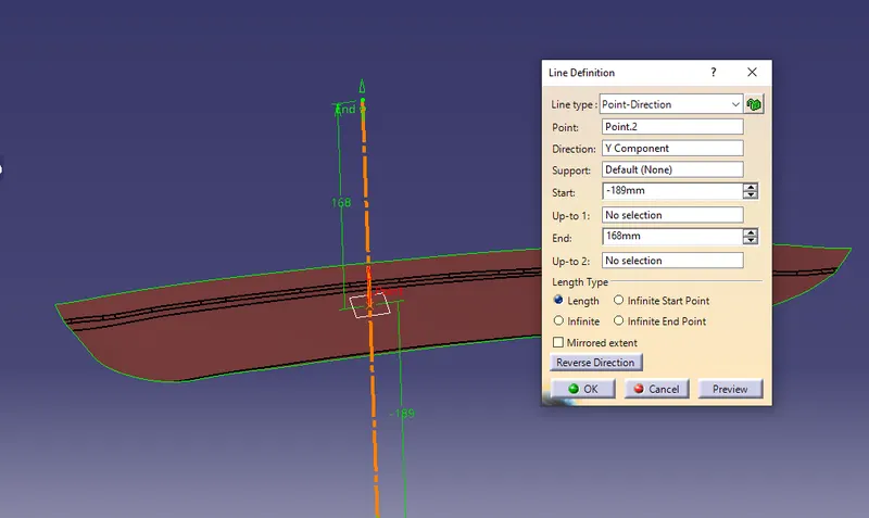
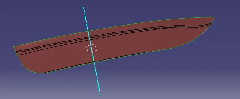
This tooling axis is not for the B Side feature .
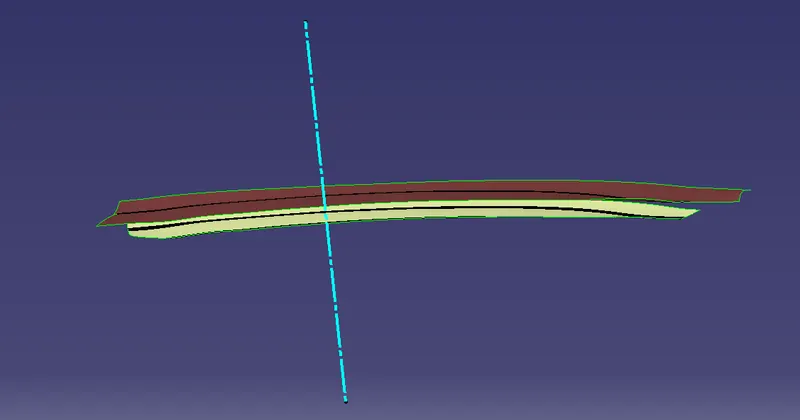
C Surface Creatione
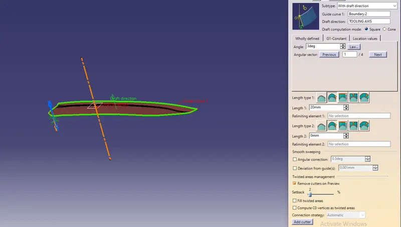
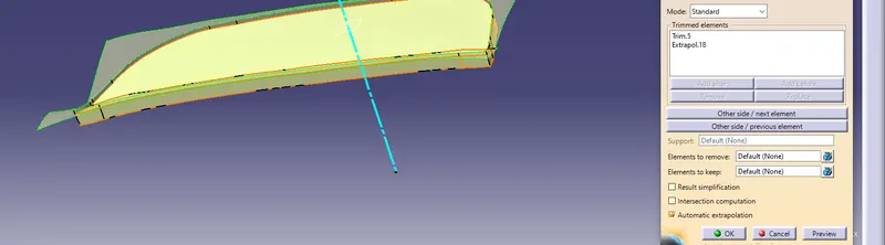
Create the boundary of A Surface by using of boundary tool, Then use the Sweep to in draft direction ,
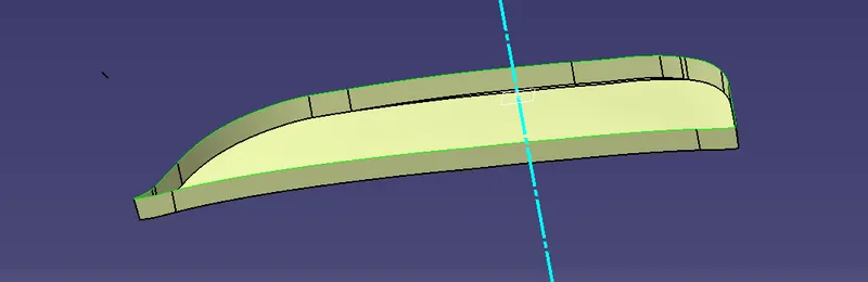
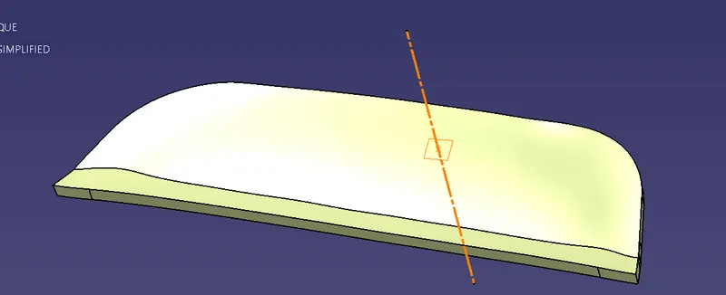
the draft angle 3 deg in tooling direction and out side of the tooling axis. Create the C surface . After C surface Creation
Takes The offset of the A Surface In 2mm and the takes Final Trim A ,B , and C surface. The Command use in this process
is
Boundary
Sweep
Extract
Trim and Extrapolate
B side Feature Creation
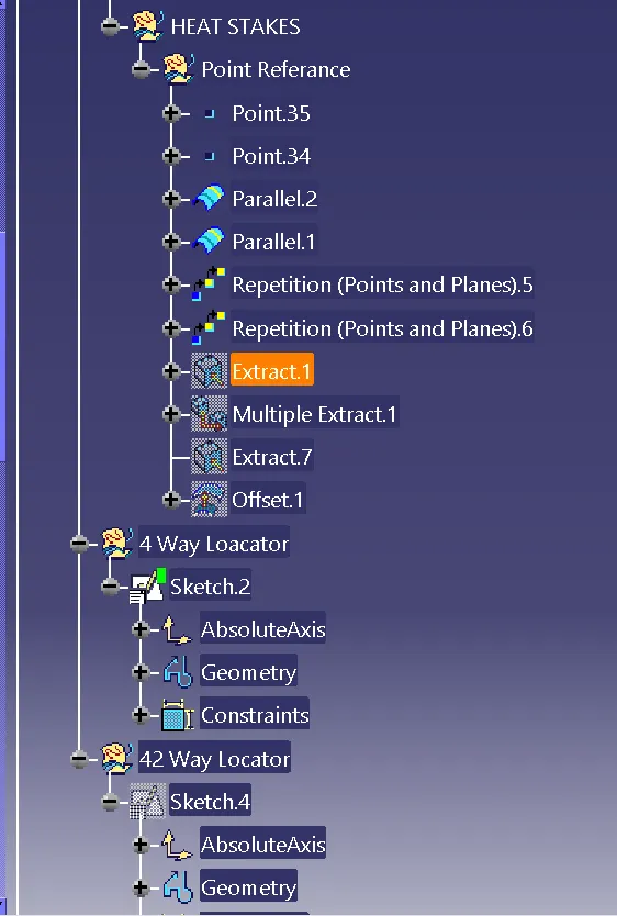
Heat Stakes
2 Way Locator
4 Way Locator
To create loctators and heat stakes on the given surface of a side door. the main purpose of these are they act as fixtures
b/w the two components. locators are used to lock the degrees of freedom and while the heat stakes are used to
attach them firmly.
Dog House
Insert a geometrical set naming locators.
Create a point on the upper surface and crearte a plane parallel through that point in the direction parallel with the surface.
Now using the points repetetion option create multiple points on the parallel curve. unhide the solid body and make sure
the heat stakes are not interfering the locators.
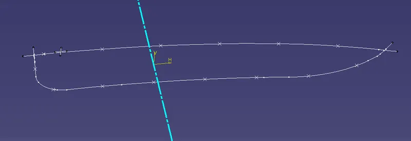
Now create a positioned sketch through the points created on the parallel curve. let the outer diameter be 7 and the inner
diameter as 5.
Using Of the pad Command and Create the Heat stakes and 4 way Locator Similarly create the the 2 way loactor
using of the iso constraind command
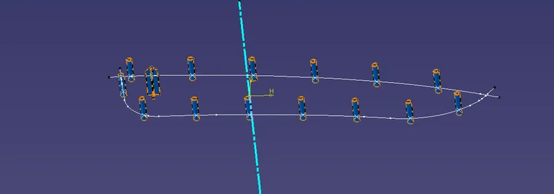
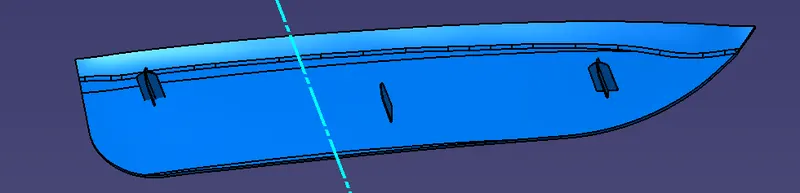
Exit the sketch and insert a part body and rename it as heat stakes and define it. pad the sketch to 1.3mm thickness and
35mm height /neutal fibre.
Now copy- paste special.. the heat stakes part body to the main folder and translate it to the other points on the parallel
curve with point to point option. similarly perform the same procedure to transalet it to the other points on the parallel
curve.
- Hence the heat stakes and locators are created according to the design guidlibnes on the applique surface. now counter holes need to be created on the attachment surface.
- Insert a geometrical set and rename it as Counter holes and define it. we can create in two different ways one by
creating a positioned sketch through the reference point from the previous sketch or by goint to part design and creating a circle through the points on the parallel curve use point-radius option. - Make sure the clearance between the surface and the features created is a minimum of 0.5mm. hence increase the
diameter of the circle by 0.5mm
Draft the heat stakes with 0.5 degree and neutral surfaces as the base and tooling axis as pulling direction.
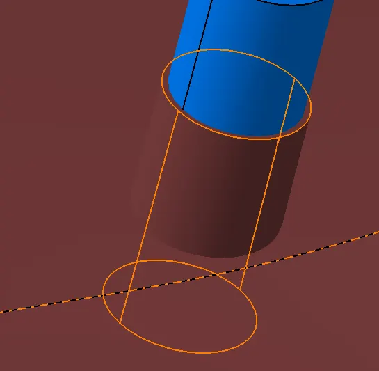
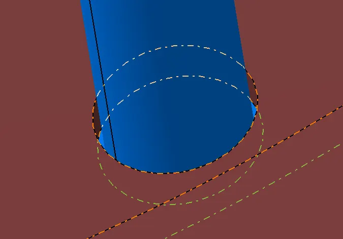
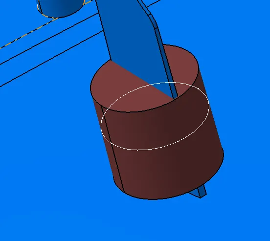
now extrude the circle to certain height and define the attachment solid part and through part body design SPLIT the
extruded surface with the solid part to get a counter hole.
Now Draft the counter part surface with 0.5 degree with the tooling axis.
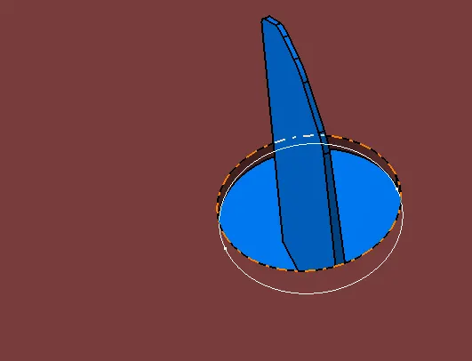
Now using Boolean operation- ADD the part bodies of heat stakes to the main part body. add edge fillets with 0.3mm
radius to all the heat stakes created.
Using the measuring tool check for the clearance between the attachment surface and the locators and heat stakes
created .
Hence the aim of creating locators and heat stakes on the applique part and clearing them through the attachment
surface following the design rules.
Now perform the Draft analysis on the components. goto Insert- Analysis - Feature Draft analysis. select the attachment
surface and place the compass on the tooling axis. inspect the component visually
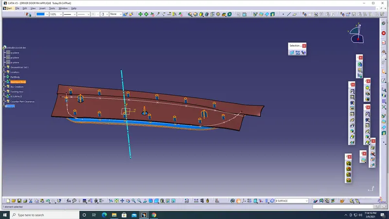
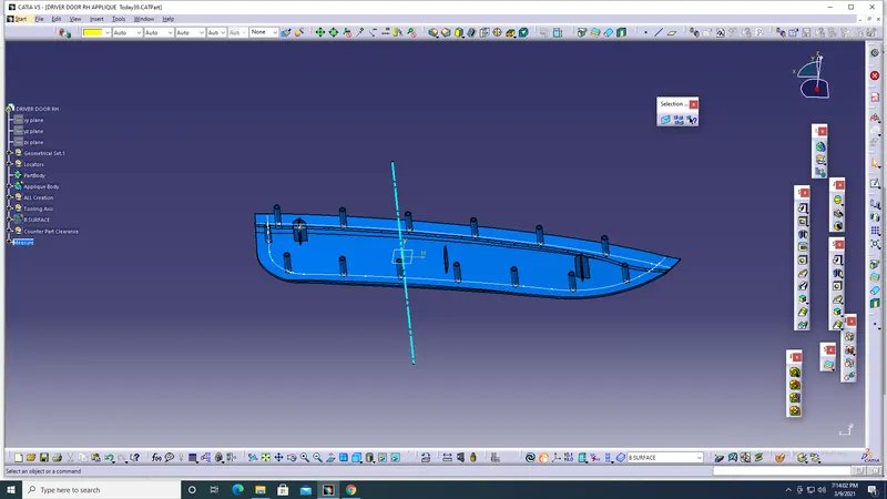
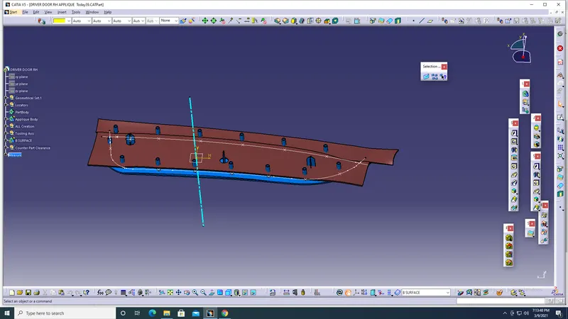
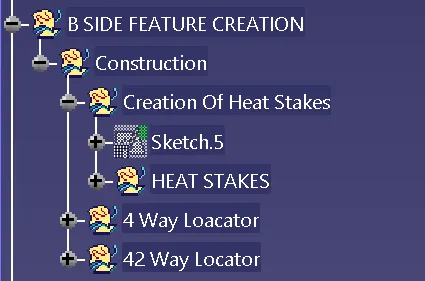
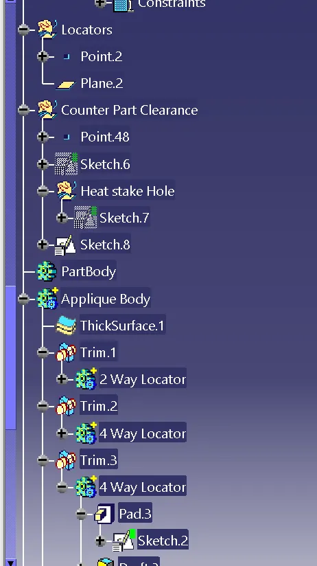
Tree structure
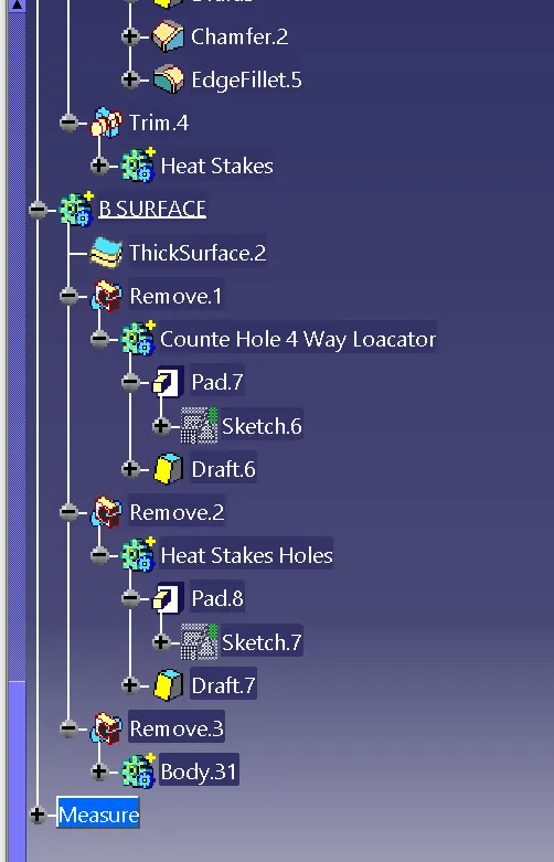
Draft Analysis-