Week 8 - Challenge 2 - Base Bracket Design
AIM -
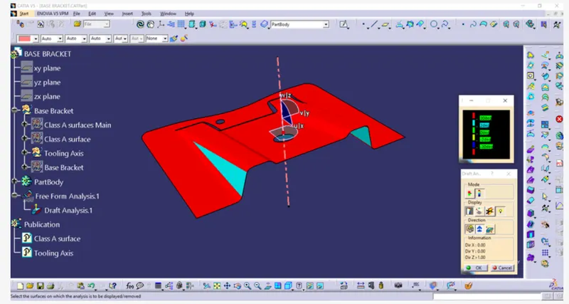
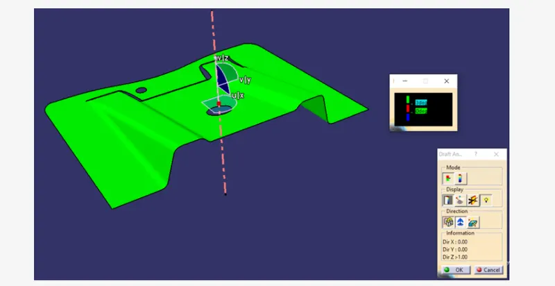
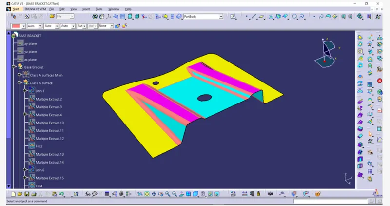
Create the Base Bracket Plastic component through the given Class-A surface. To begin with, the tooling axis for the given Class-A Surface should be created meeting the requirements of the draft angle and at the end perform the Draft analysis on the model.
Command used in this process
- Point
- Line
- Intersect
- Bisecting line
- Axis system
- Extract
- Trim and Untrim
- Extrapolate
- Offset
- Fillet
- Measure
- Swip
- Draft Analysis
Step 1
Check the continuty of the of the A surface by using of the boundary or join command
if the surface is closed then start the next process.
Step 2
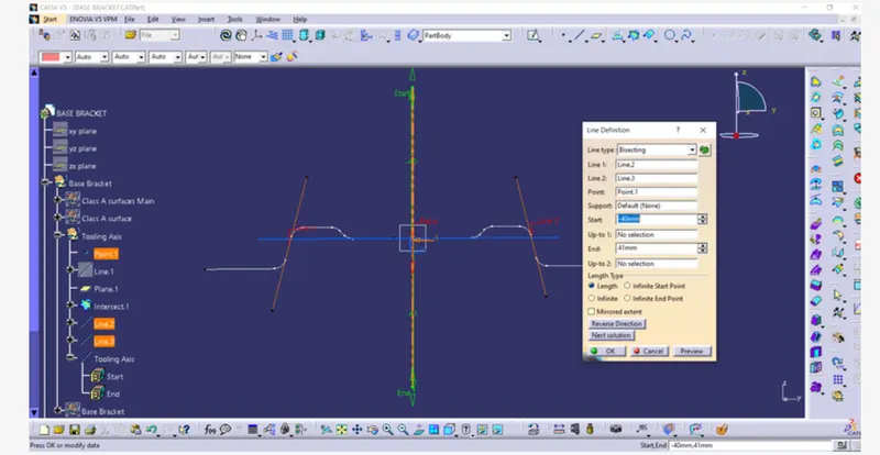
Ceate the Tooling axis with the help of bisecting line
- Takes the intersect of the xz and yz palne and create the line and bisect them.
- Now by using of the xz and yz plane bisecting line create the tooling axis
- After creating tooling axis to publishing the tooling axis
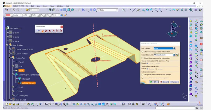
Intersect creation by using of the takes plane .
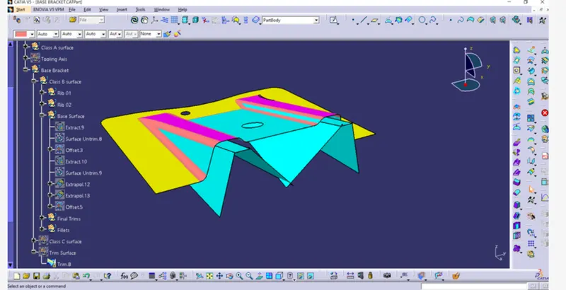
STEP #3 Creation of the B surface with help of the a surface
- Extract the each surface of the A class surface
- Untrim the all extract surface
- extrapolate the all surface
- and Trim the surface
- takes the offset of the Trim surface
STEP #4
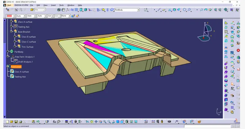
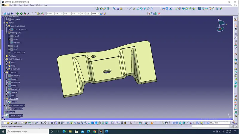
Creation of the C Surface- The surface which will connect the A and B surface .
Extract the boundary of the a surface and swip the boundary by using of the swip
command .
Then trim the surfaces
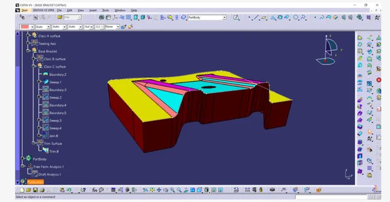
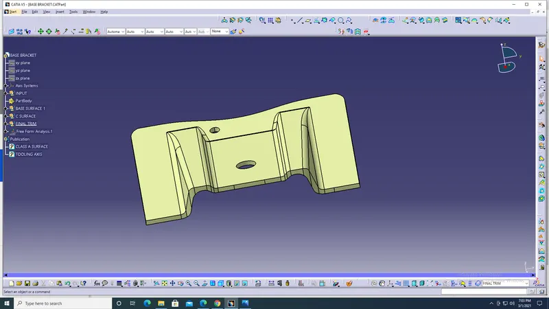
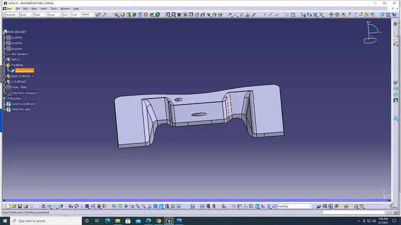
After completing the above process check the continuty of the body
and the makes the solid body and doing the draft analysis
STEP 5
Draft Analysis
- On the shading matarial mode
- Click the draft analysis and click the compass mode
- Set on the tooling axis
- and check the draft angle surface