Week 9 - Project 1 - Door Applique Design with Engineering Features
DESIGN OF APPLIQUE
TOOLING AXIS
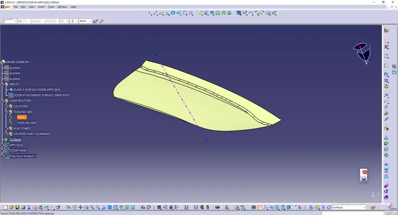
1) We had flat class A surface so directly created point over surface and drew line in Y direction as tooling axis
4 WAY LOCATORS
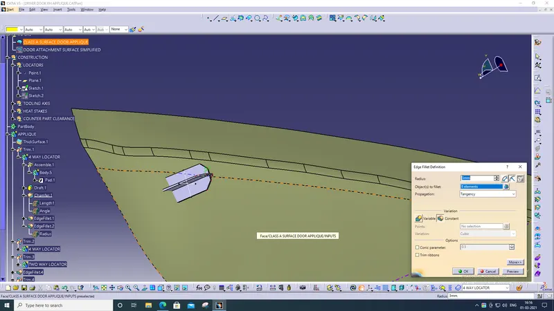
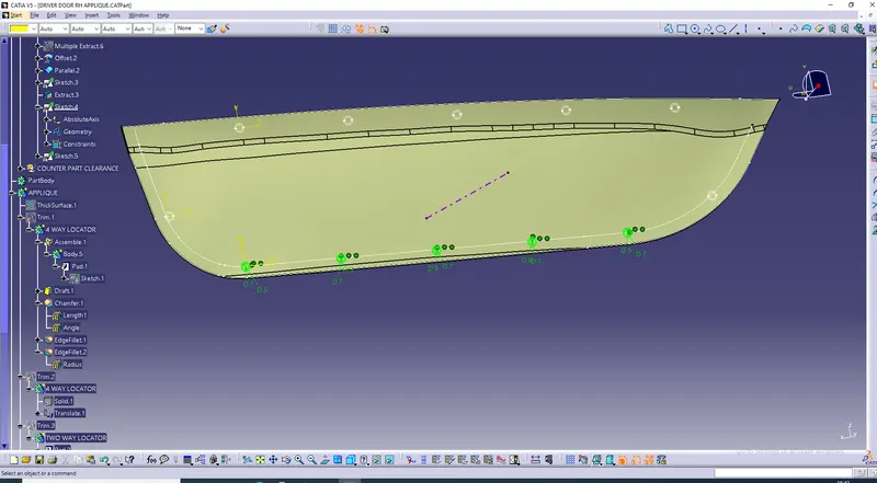
1) first thicked class A surface. drew positioned sketch of 4 way locator and paded it. gave draft angle of 0.5 degree to it and further chamfered and edge fillet to it. finally trimed with thicked applique.
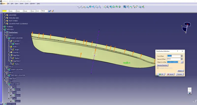
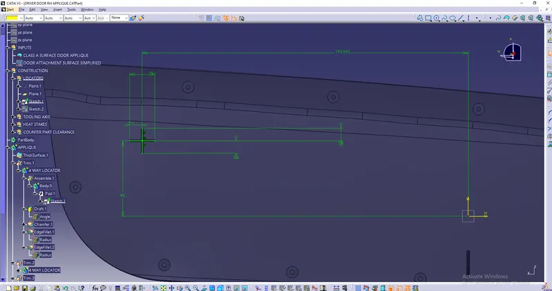
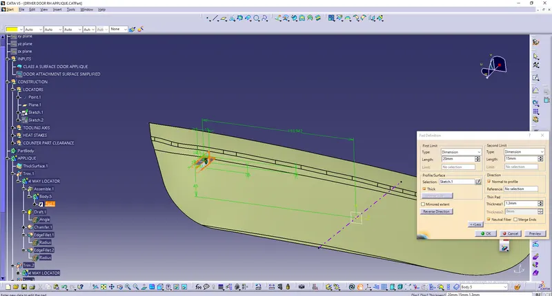
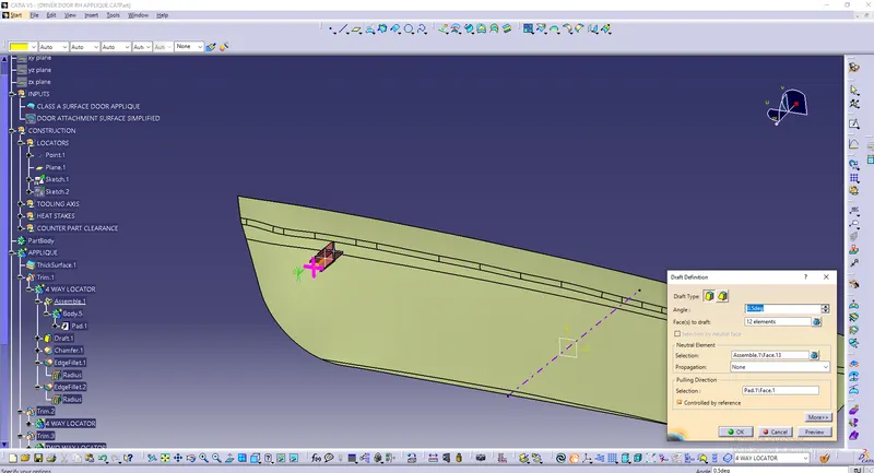
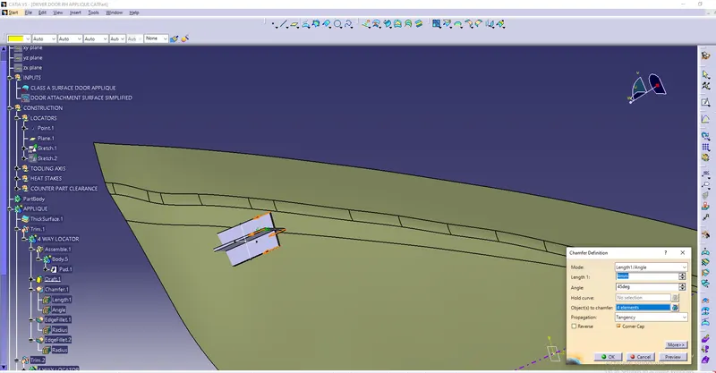
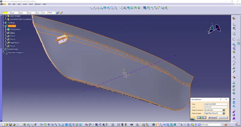
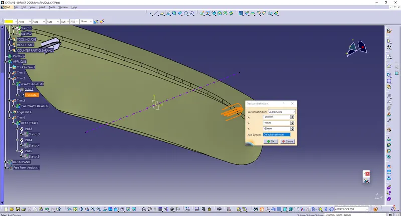
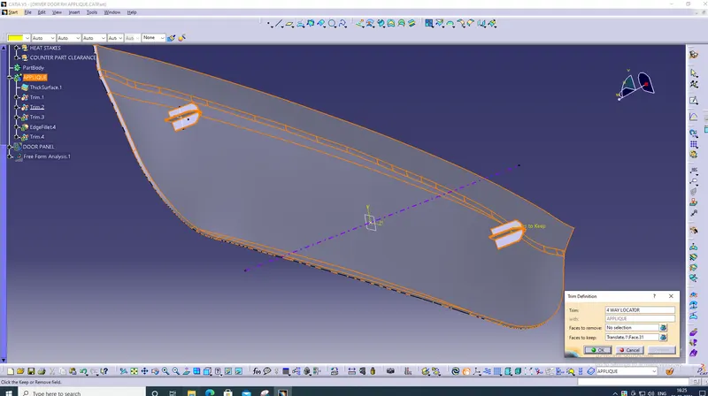
2) Translated 4 way locator body to appropriate distance and also trimed with applique body.
TWO WAY LOCATOR
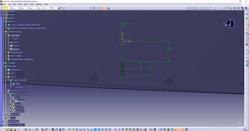
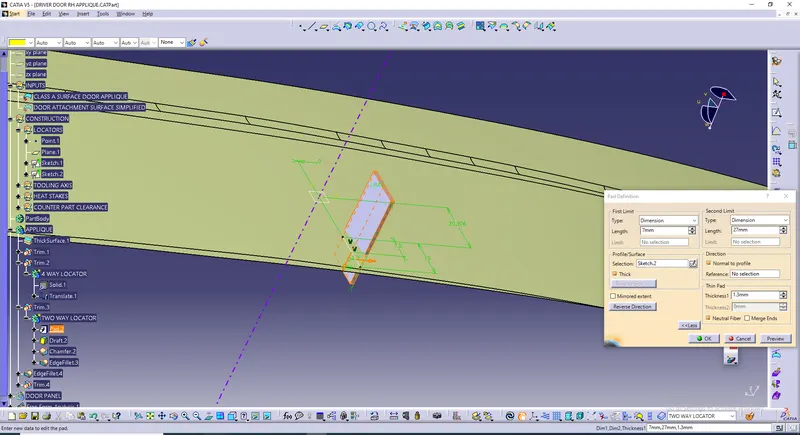
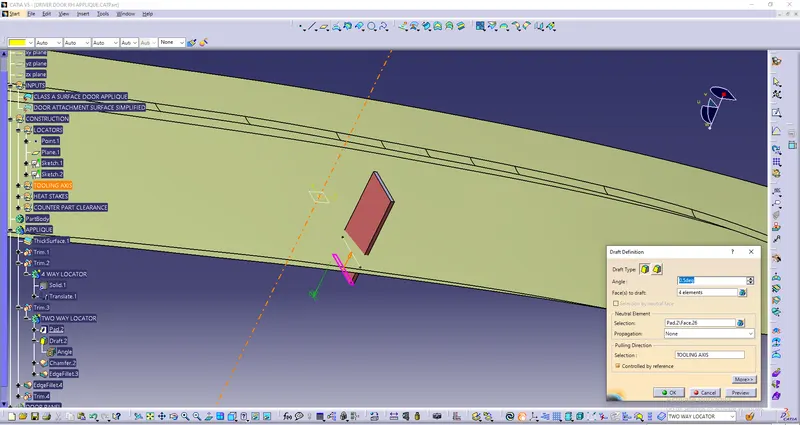
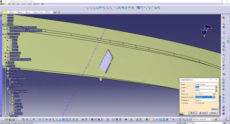
1) Drew 2 way locator positioned sketch and paded it. gave draft angle of 0.5 degree and further gave chamfered and edge fillet to it. finally trimed with applique body.
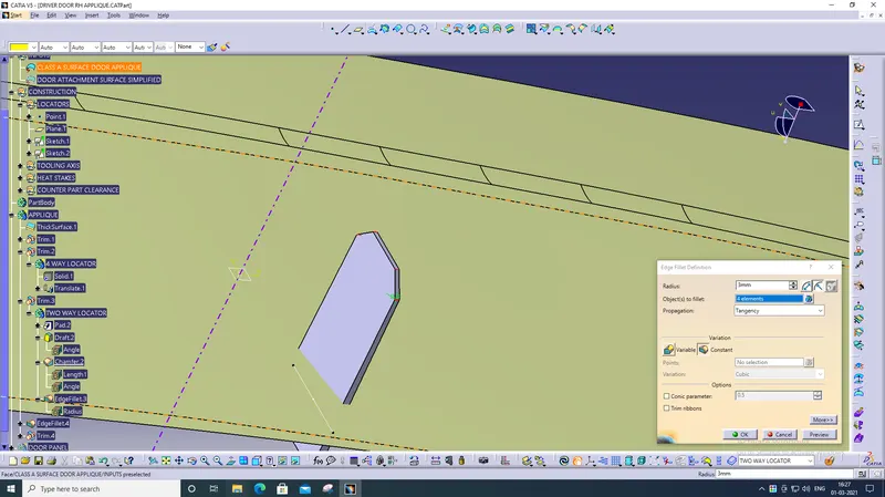
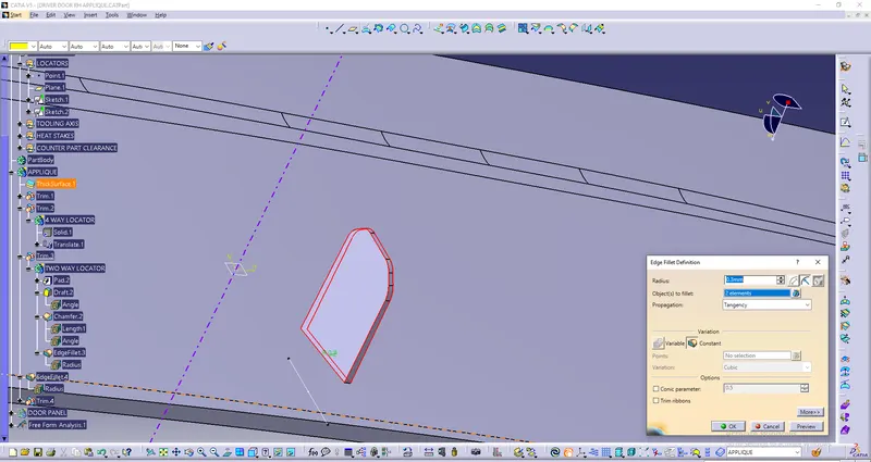
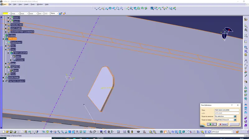
HEAT STAKES
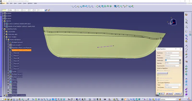
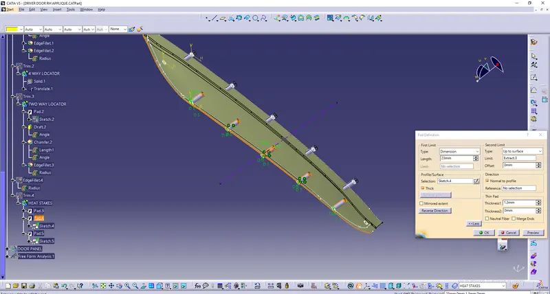
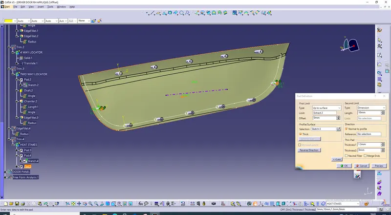
1) Multipled extracted upper edge of surface and gave smooth curve. drew parallel curve at appropriate distance and created repeated points over plane. drew sketch of heat stakes over it.
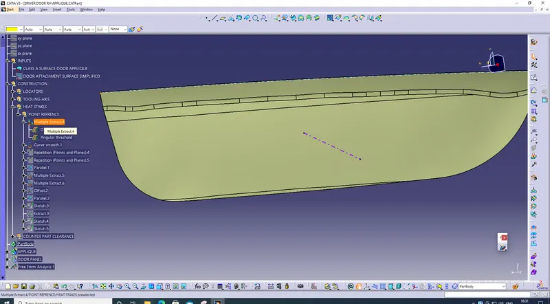
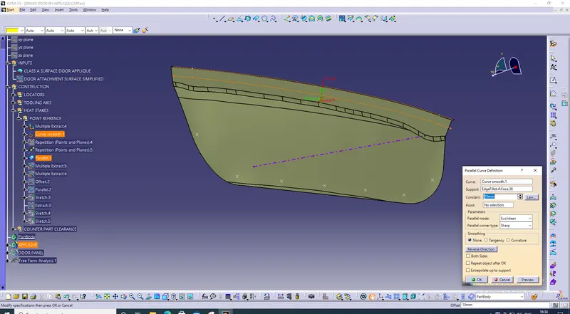
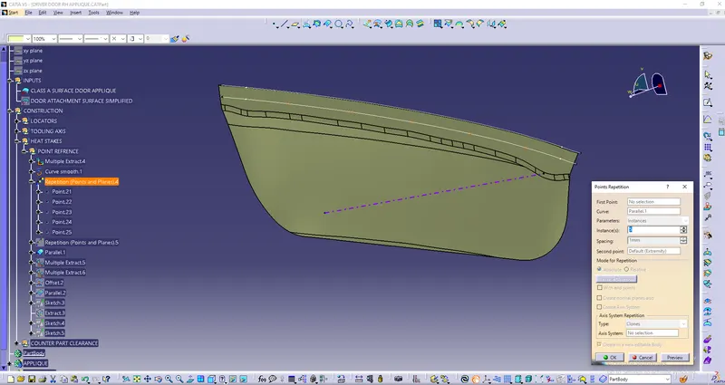
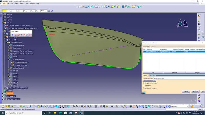
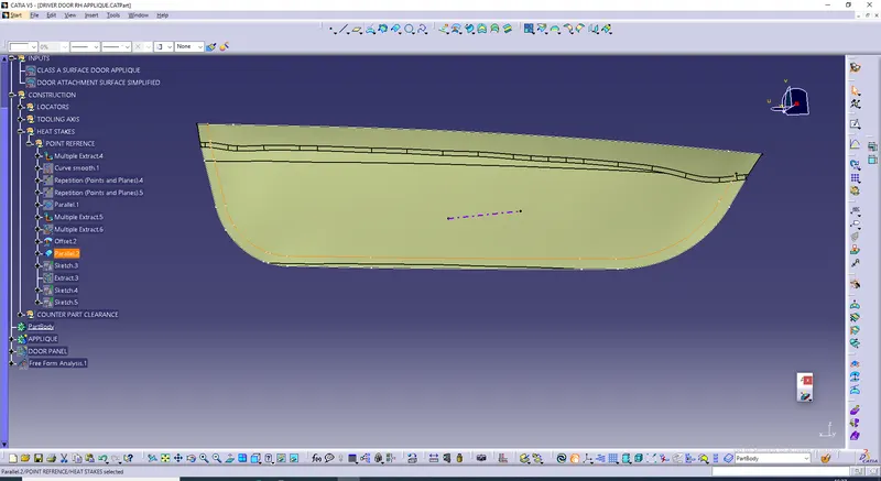
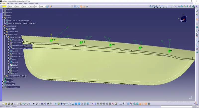
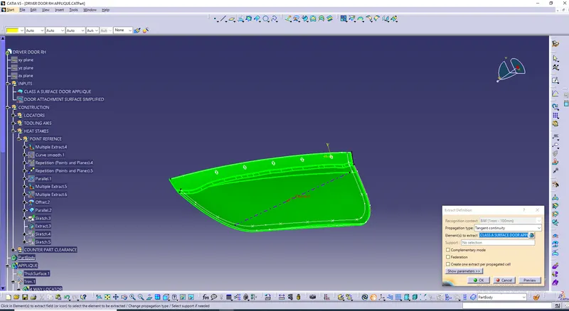
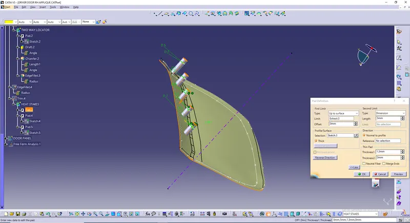
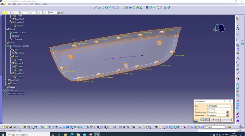
2) Extracted class A surface and paded heat stakes till surface. similarly drew and created heat stakes over lower parallel plane and trimed with applique body.
COUNTER PART CLEARANCE
FOR FOUR WAY LOCATORS
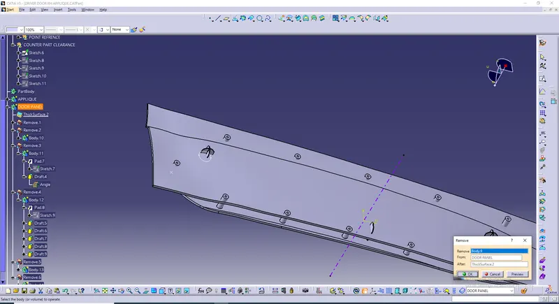
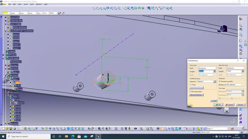
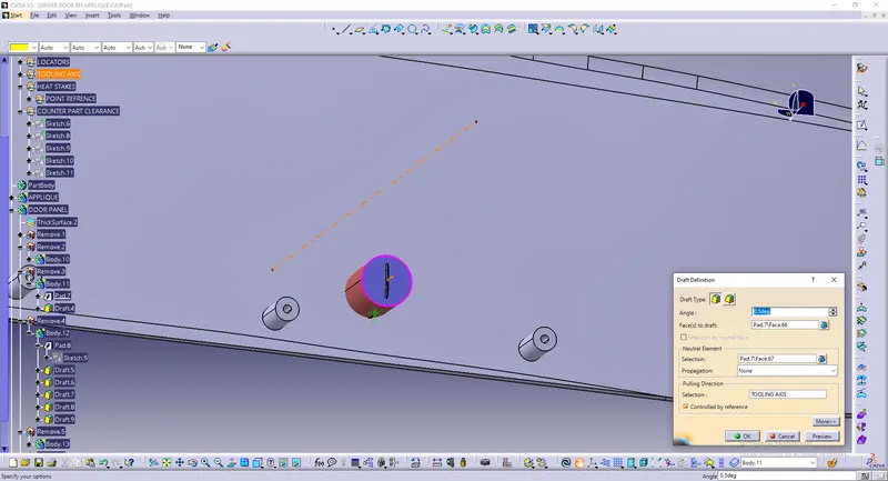
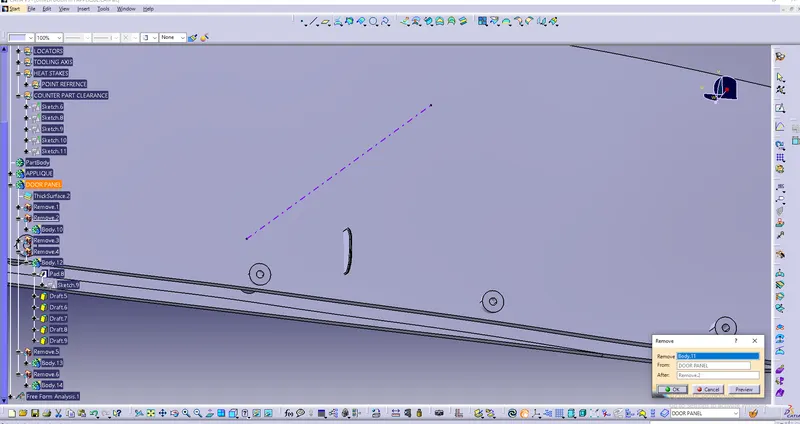
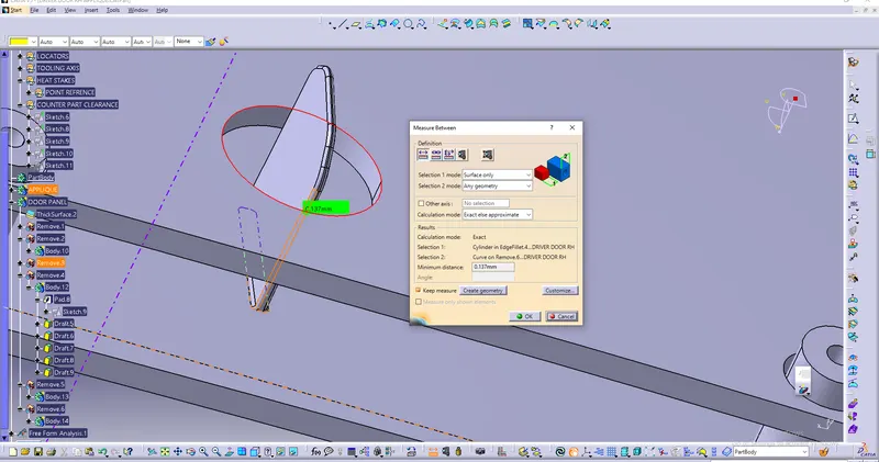
1)First thicked door panel and drew circle over it. paded it and gave draft angle of 0.5 degree to it. further removed it from thicked door panel and checked whether the distance between two way locator and hole edge was not greater or less than 0.1
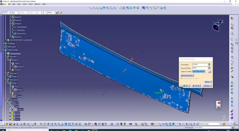
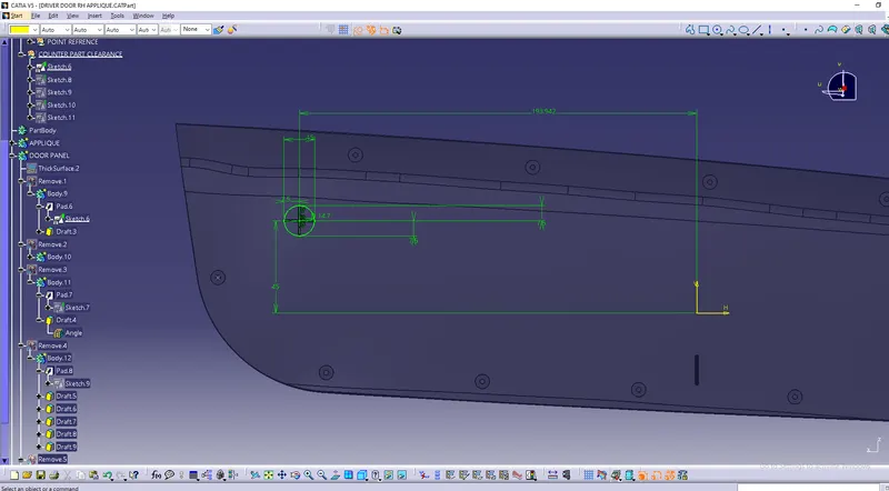
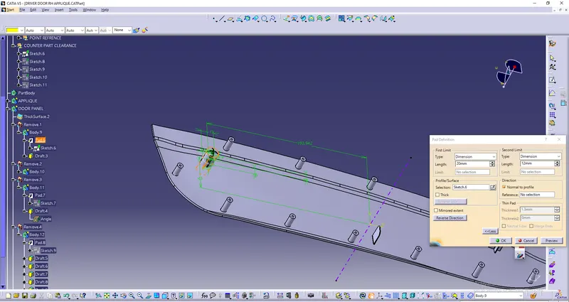
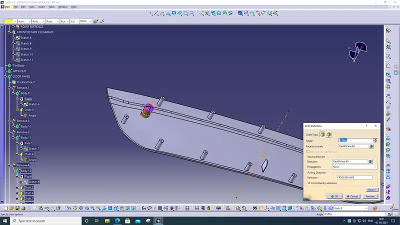
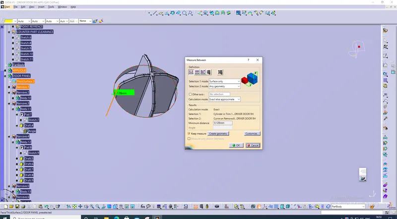
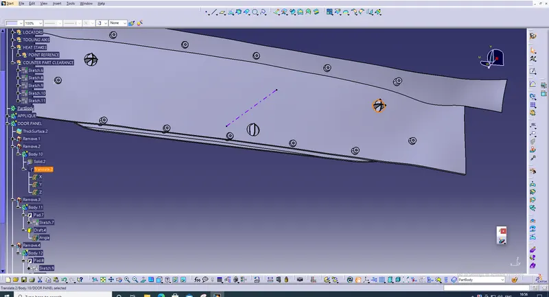
2) Translated this whole body to other two way locator and removed from door panel. here also checked clarance was not greater or less than 0.1
FOR TWO WAY LOCATORS
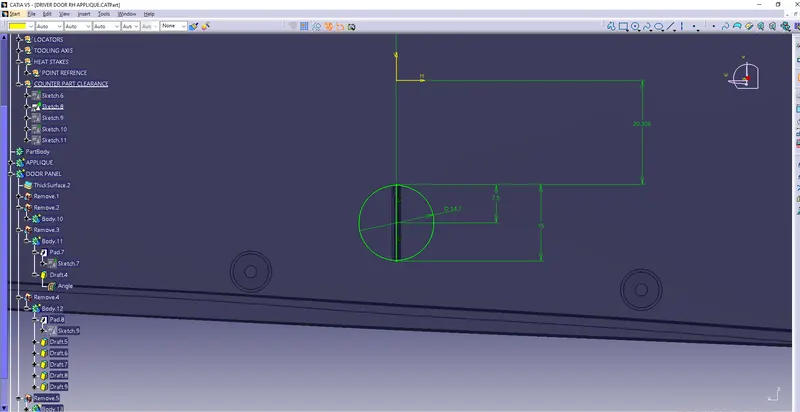
1) Drew circle over it and paded it. gave draft angle 0.5 degree to it. removed it from door panel body and checked whether the clarance distance between two way locator and edge of hole was not greater or less than 0.1.
FOR HEAT STAKES
1) Similarly like locators drew circle over heat stakes. paded it and gave draft of 0.5 degree to it and removed it from door panel. checked whethere clearance distance between heat stakes and hole edge was not greater or less than 0.5
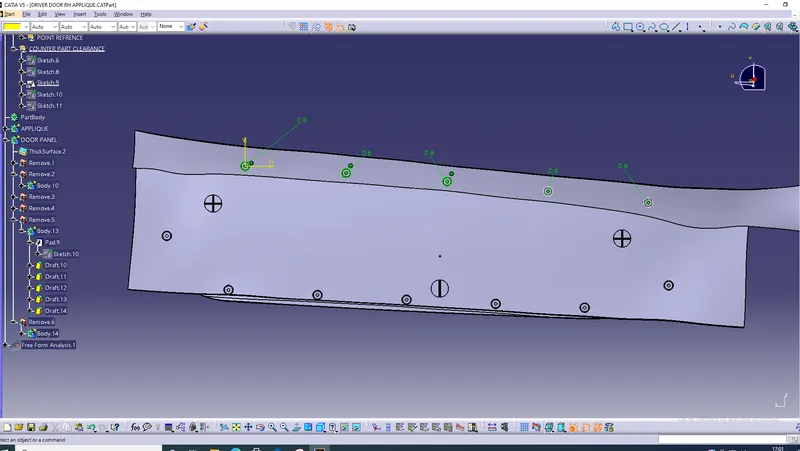
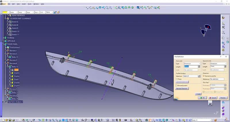
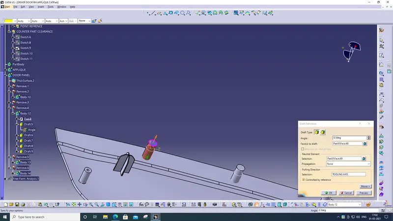
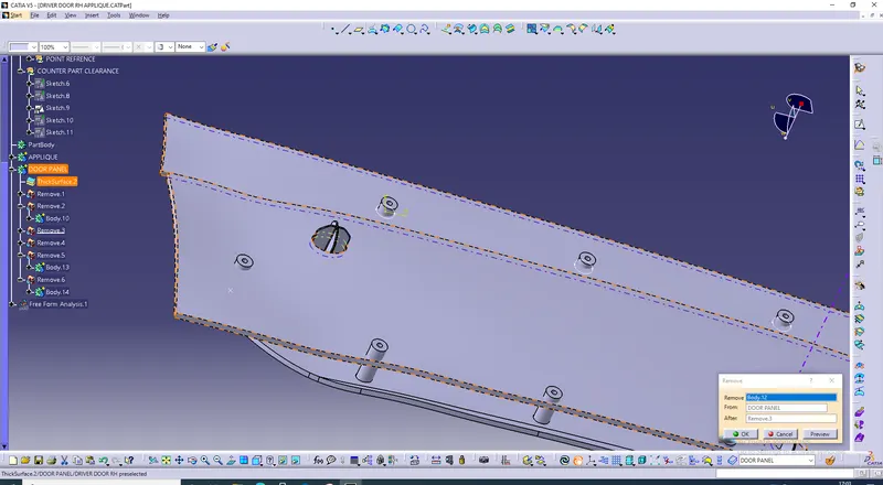
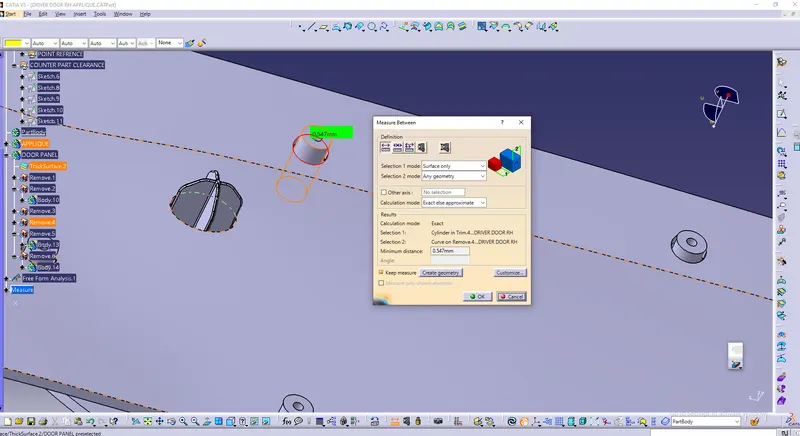
2) Similarly process is used for all heat stakes.
DRAFT ANALYSIS
DRAFT ANALYSIS OF CLASS A SURFACE
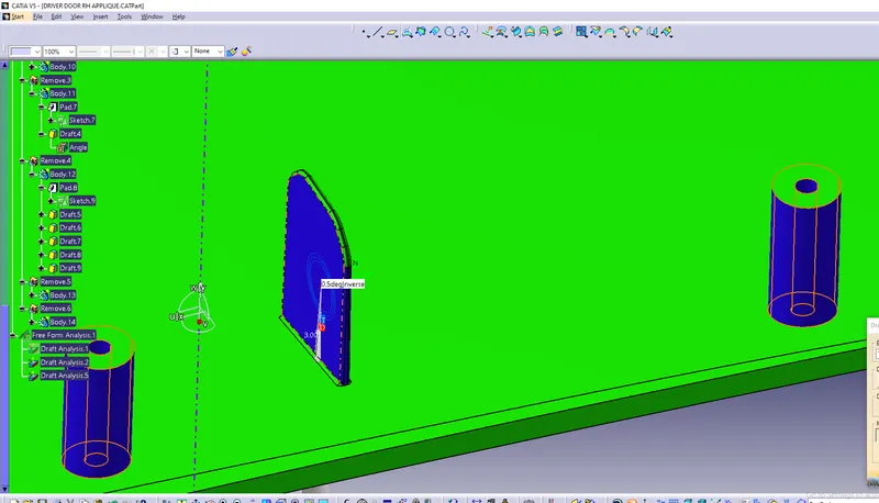
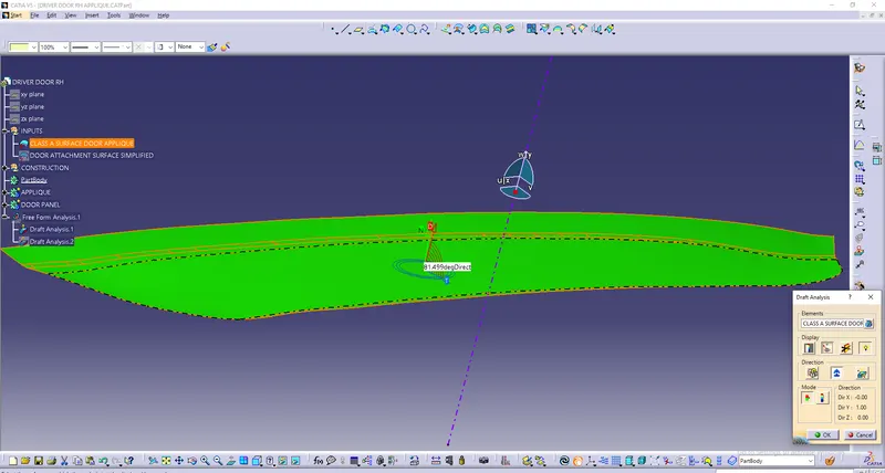
1) For draft analysis went through drfat analysis comand. first selected and draged compass over tooling axis then locked compass and againg draged compass over tooling axis and clicked over surface. there were showed green colour over surface means draft was correct because class A surface was flat 90 degree.
DRAFT ANALYSIS OF FINAL COMPONENET
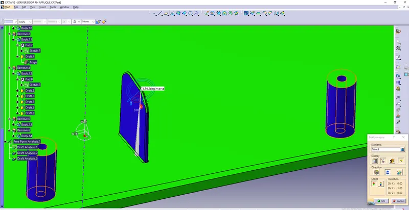
1) Similarly went through drfat analysis comand. first selected and draged compass over tooling axis then locked compass and againg draged compass over tooling axis and clicked over surface. different colour variants showed over surface. For 4 way locators outside surfaces showed blue colour because we gave 0.5 degree draft and upper surface was showed green because it had draft angle greater than 3 degree.
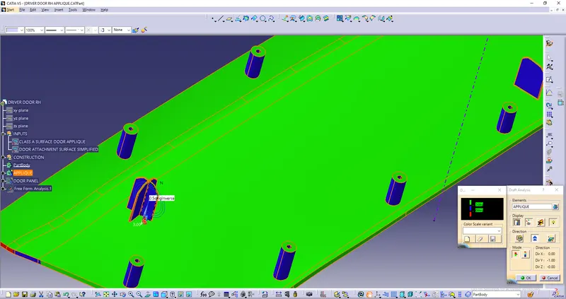

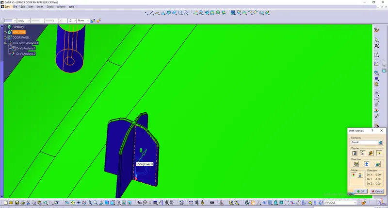
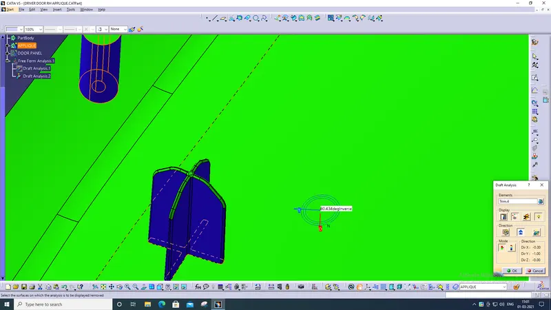
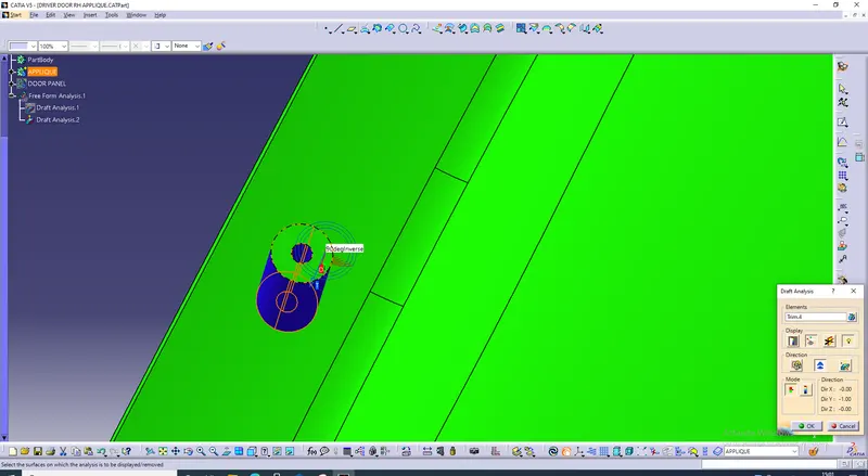
2) For heat stakes here also same colour variants was showed. green colour showed over upper flat surface and outer surfaces showed blue due to drafted it 0.5 degree.
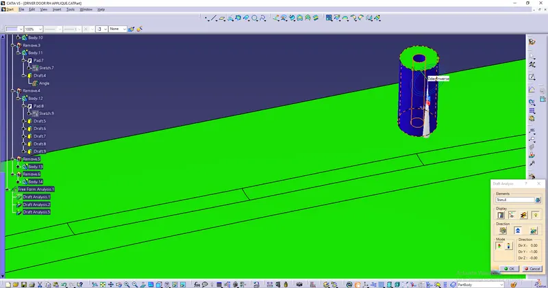
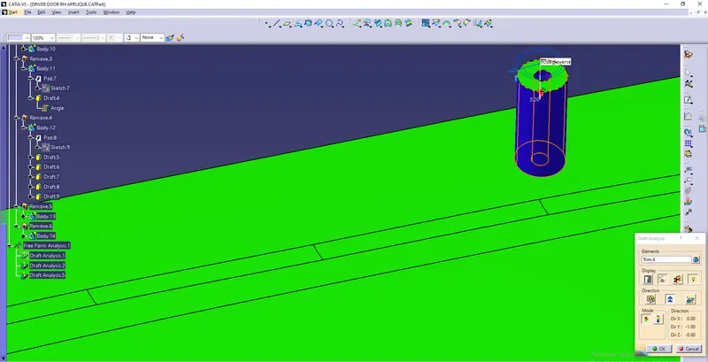
3) For 2 way locators green colour was showed upper surface of it because it had draft angle more than 3 degree. but in oter surfaces was showed blue because we drafted it with 0.5 degree .