Week 9 - Project 1 - Door Applique Design with Engineering Features
Hi colleagues
I have opened the Part – DRIVER DOOR RH and looked a little bit what should be done...First I am going to rename given Geometrical Set with given surfaces as INPUT and Insert new Geometrical Set – CONSTRUCTION and under it TOOLING AXIS,CLASS A SURFACE (there I will copy DRIVER DOOR RH from INPUT),CLASS B SURFACE,CLASS C SURFACE surfaces.
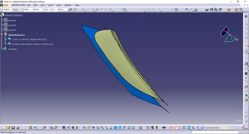
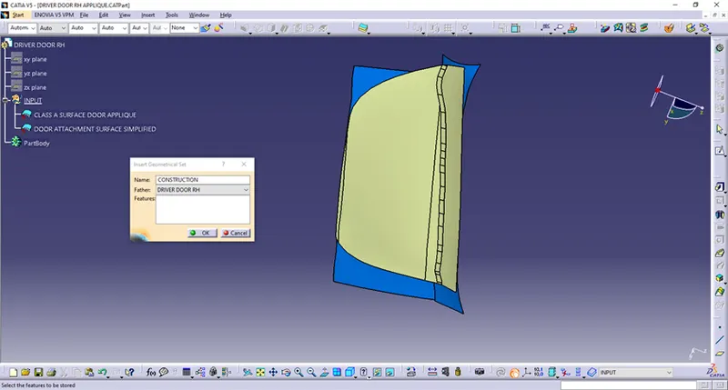
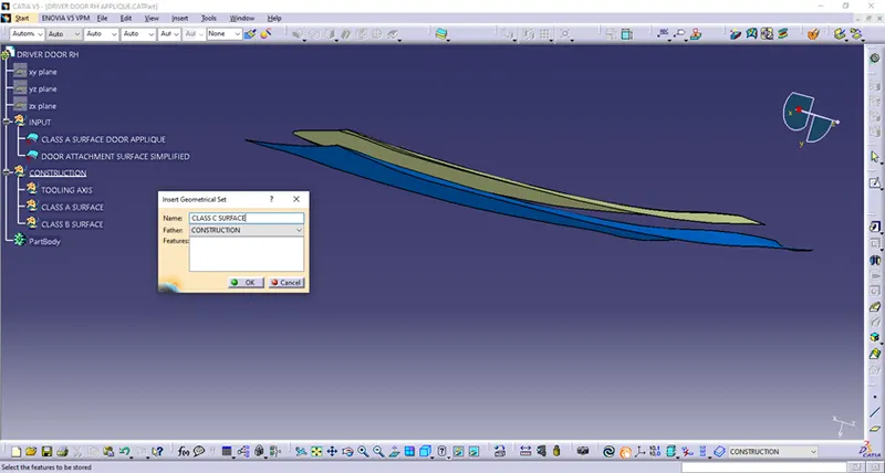
I have changed graphical properties of a CLASS A SURFACE to have a better overview.
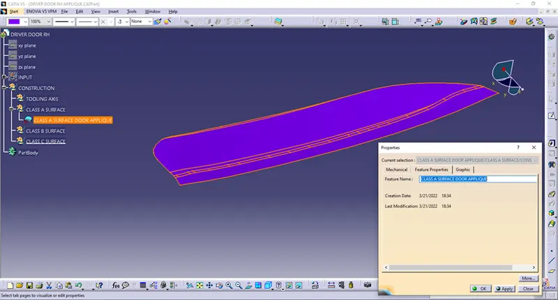
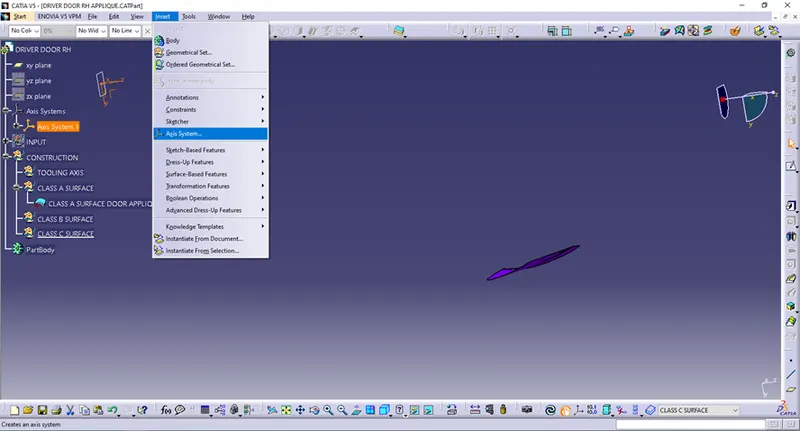
I have inserted new Axis System to see a position of global Axis sistem in correlation to my part (orientation and similar) and I have decided to insert Axis system for a part approximately in the middle and perpendicular on it.
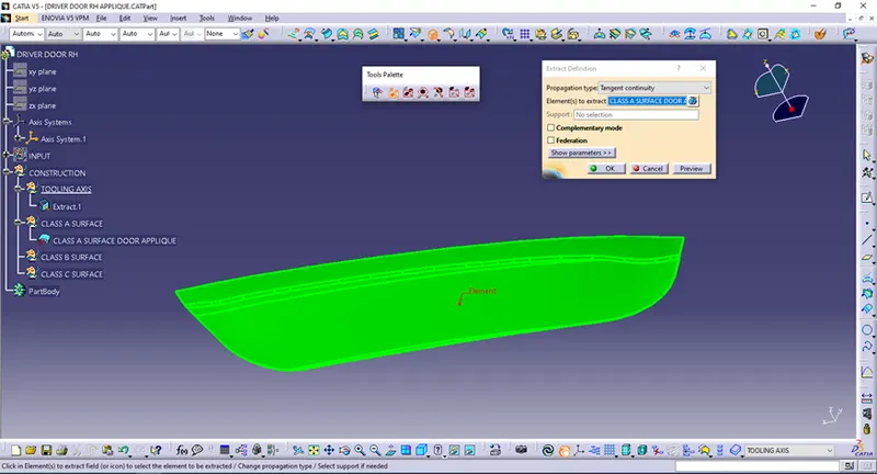
Then,I have extracted CLASS A SURFACE as follows.
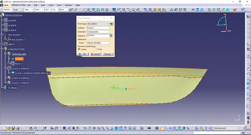
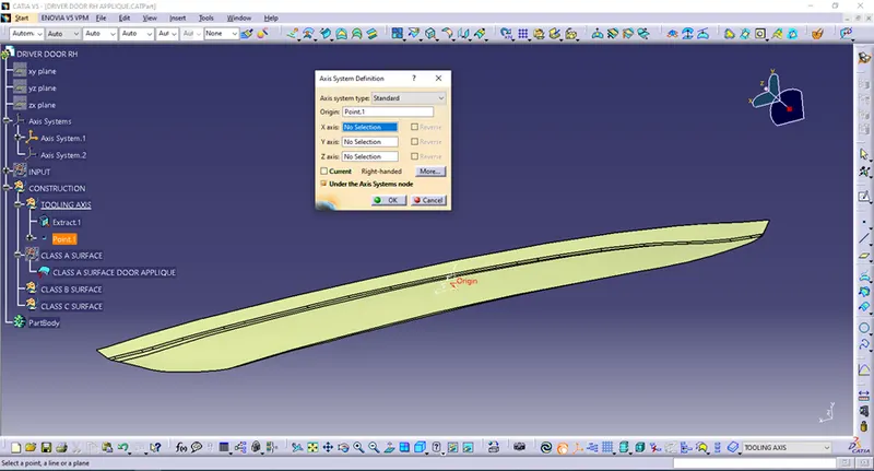
On that surface I have drawn a point and in it inserted Axis system.
I have intersected the surface with a YZ plane to get a base for bisecting lines.
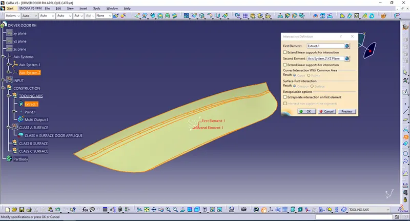
Then I have a drawn lines for bisecting as follows.
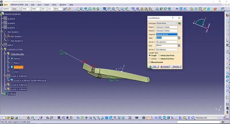
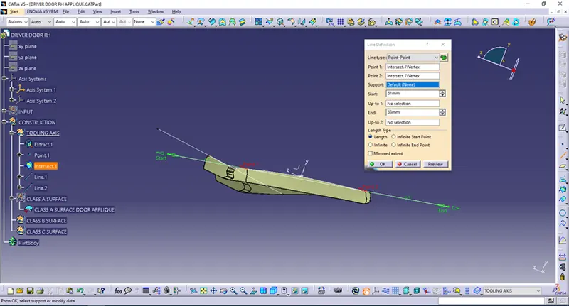
On that base is bisecting line constructed – that will be mine TOOLING AXIS (the other direction is not so curved,so constructed TOOL AXIS will do).
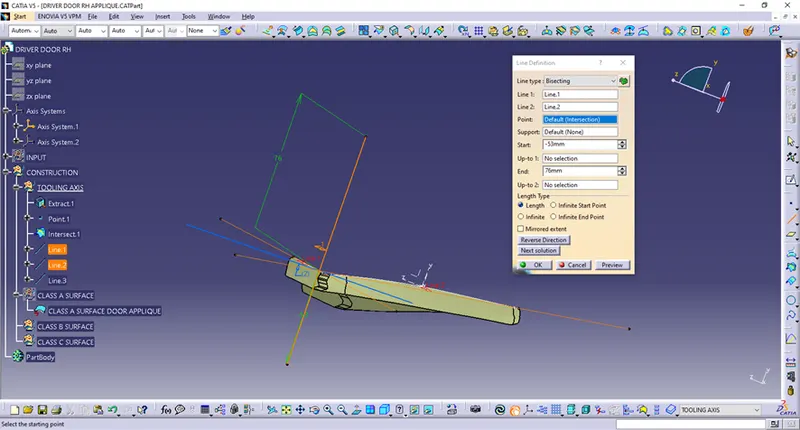
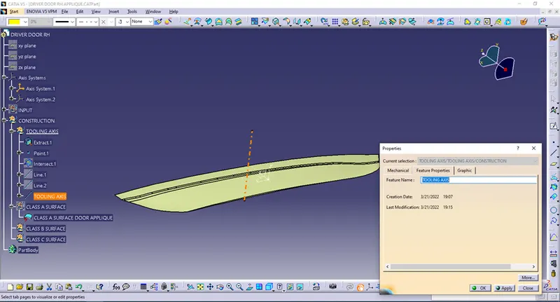
I have renamed a line as a TOOLING AXIS and changed its properties.
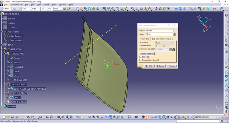
I have offseted CLASS A SURFACE for a 2.5mm – I have offseted all extracted surface for a 2.5mm without problems (so,I will move forward without separately doing procedure extract-untrim-extrapolate-offset...).
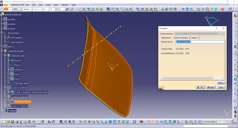
I am changing the name of so offseted surface as a CLASS B SURFACE and graphical properties of it.
Now,I am going to construct CLASS C SURFACE.First I will do a boundary on a CLASS A SURFACE.
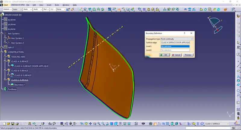
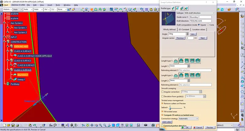
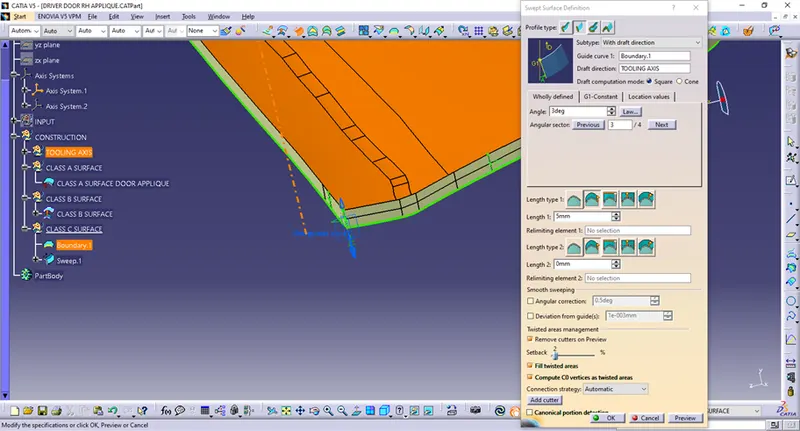
I have to extrapolate CLASS B SURFACE,to be able to trim the surfaces.I have done it and it went good (I had a little luck – if that was impossible,I have to extract,extrapolate and rejoin the surfaces.I have seen the surface is not too much flexed and curved and tried on this way,with complete surface).
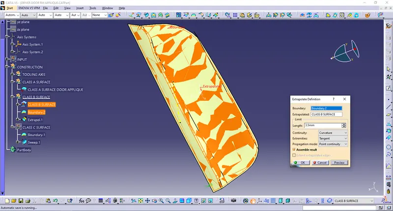
Now I am going to rename a Sweep.1 as CLASS C SURFACE and change its graphic properties.Then I will insert once more Geometrical Set – DRIVER DOOR RH,and there I will join CLASS A SURFACE and a CLASS C SURFACE and that Join trim with CLASS B SURFACE to get a closed surfaces.
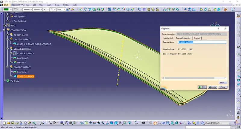
I have made a mistake – CLASS B SURFACE is actualy Extrapolate.1 – I should rename those features.
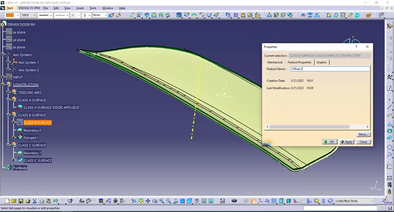
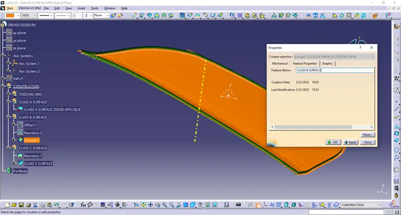
Now goes inserting new Geometrical Set DRIVER DOOR RH,as it is said before in upper section.
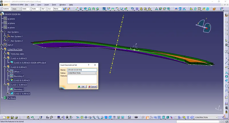
I have done check for a Sweep – CLASS C SURFACE,there is a problem,when I look normal on the CLASS A SURFACE,CLASS C SURFACE should be visible till CLASS B SURFACE and it is not...I should deal with a Sweep for CLASS C SURFACE.
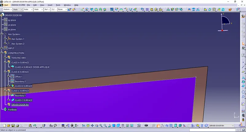
The other side shows also.
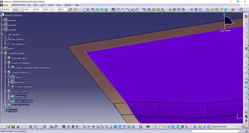
Sweep for CLASS C SURFACE should be done outwards and I have increased a value on 5deg.
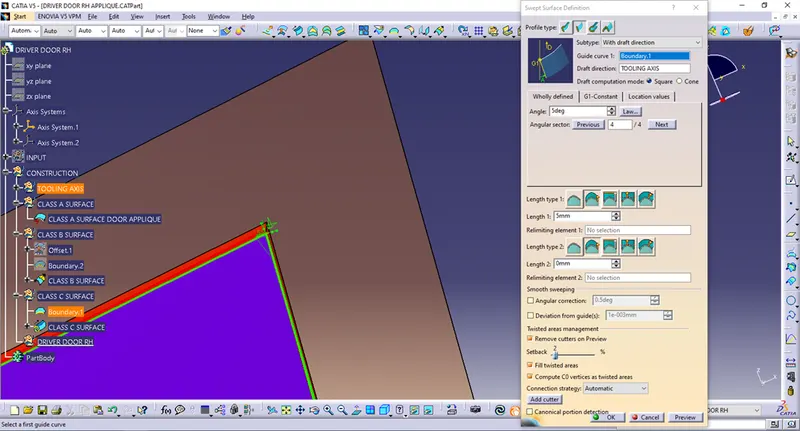
It looks good now.
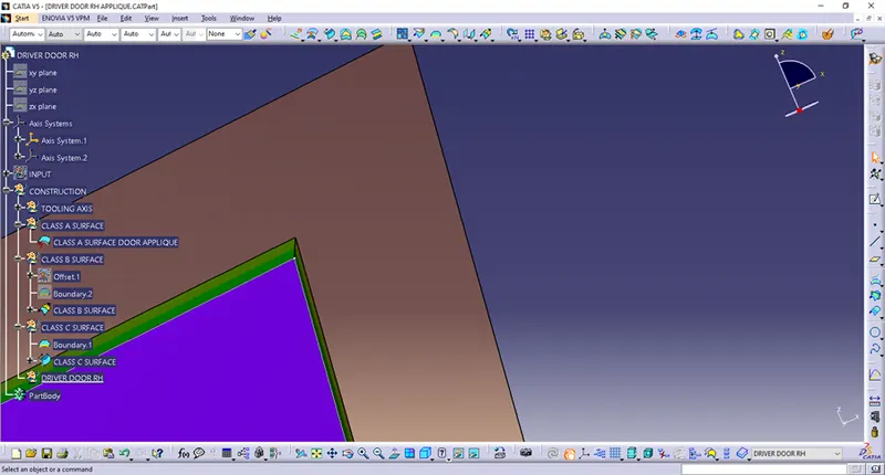
But,the other side does not look good – I will deal with it.
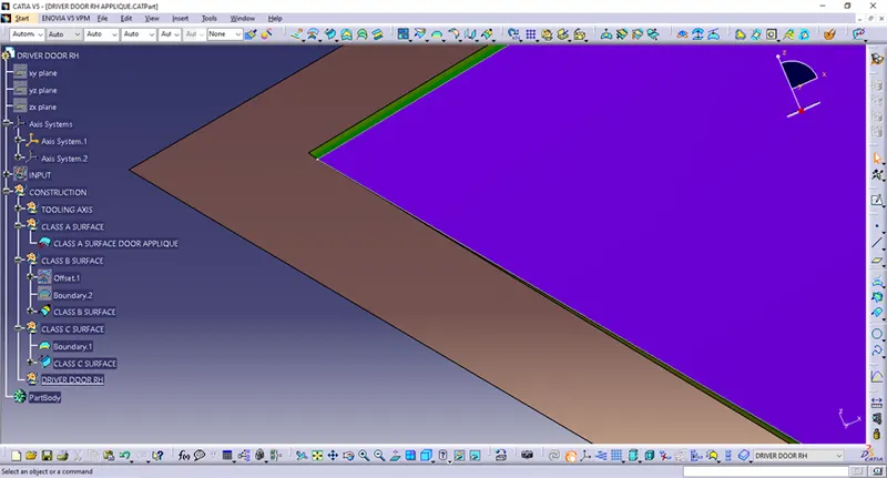
I will divide Sweep in two surfaces.
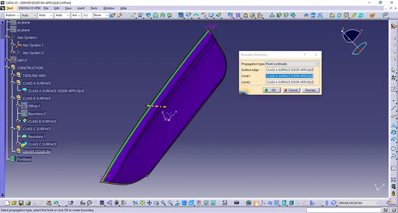
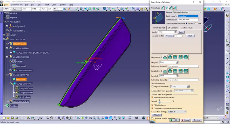
And the other sweep is
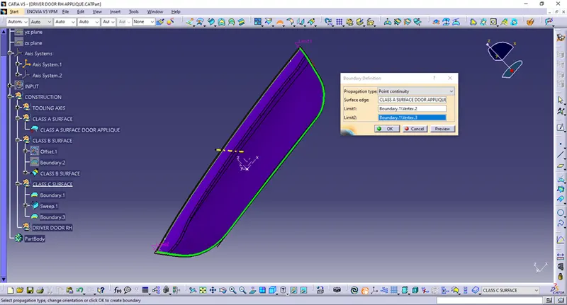
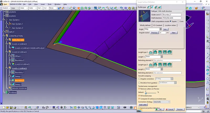
There are some gaps that should be closed.
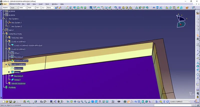
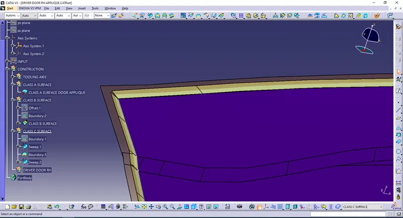
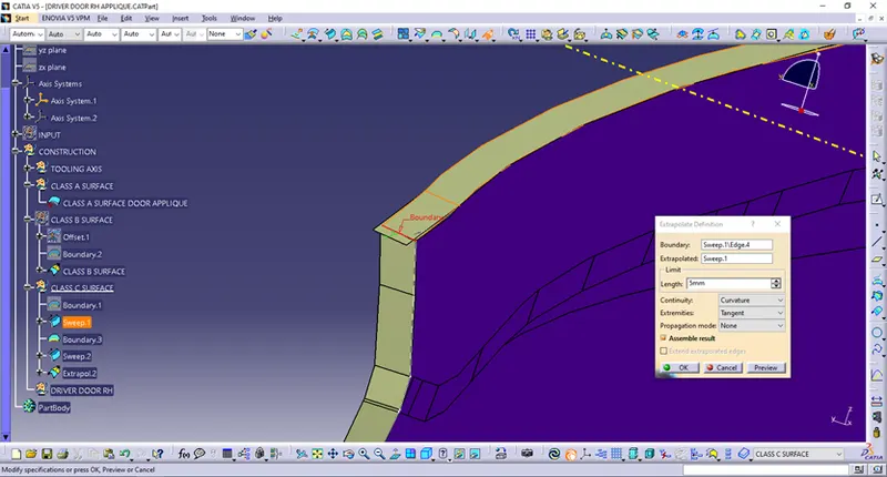
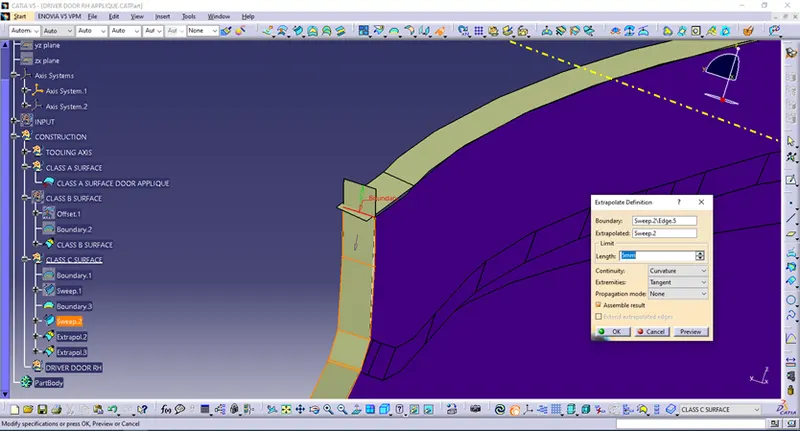
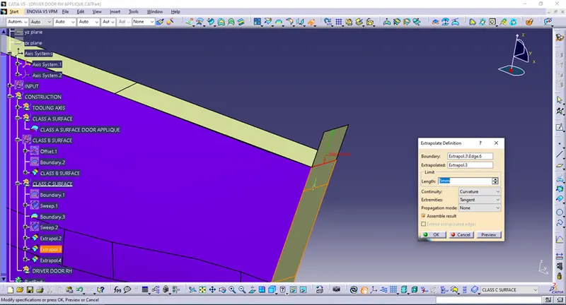
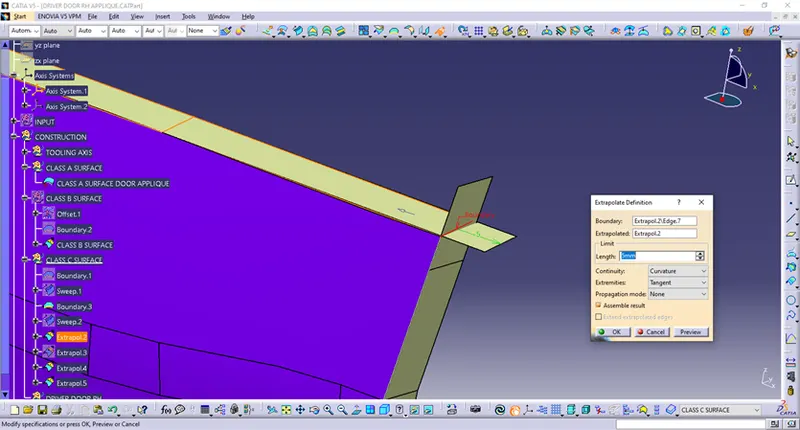
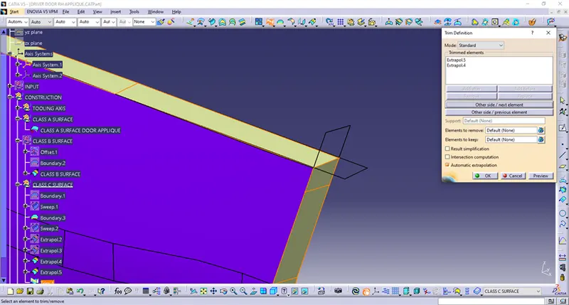
Now comes trim.
And this is my CLASS C SURFACE.
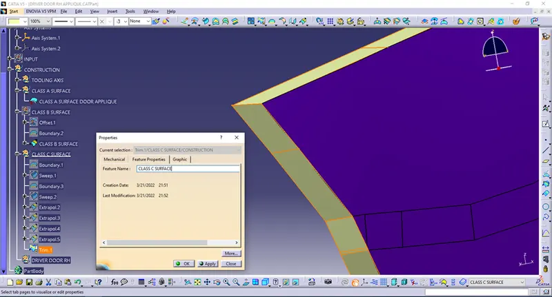
I have checked it once again.
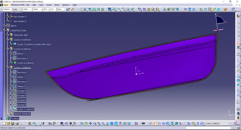
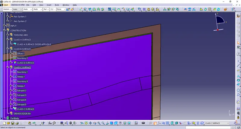
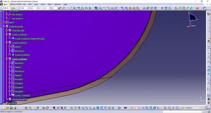
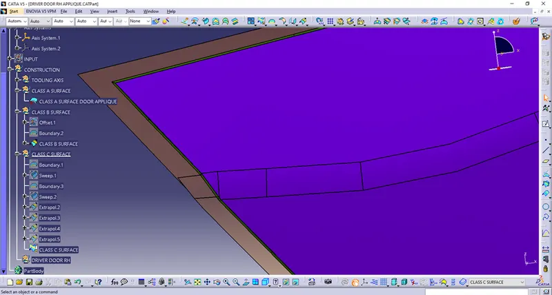
Now it looks good overall.
As a pair times already said,now comes join CLASS A SURFACE and CLASS C SURAFCE and trim with a CLASS B SURFACE as it is shown on images bellow.
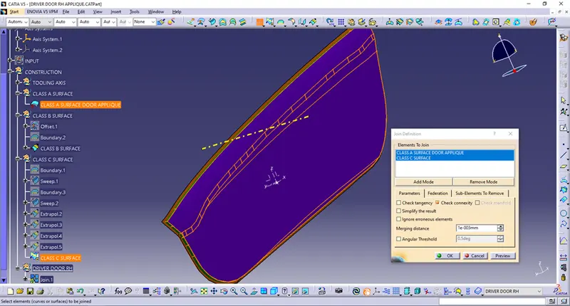
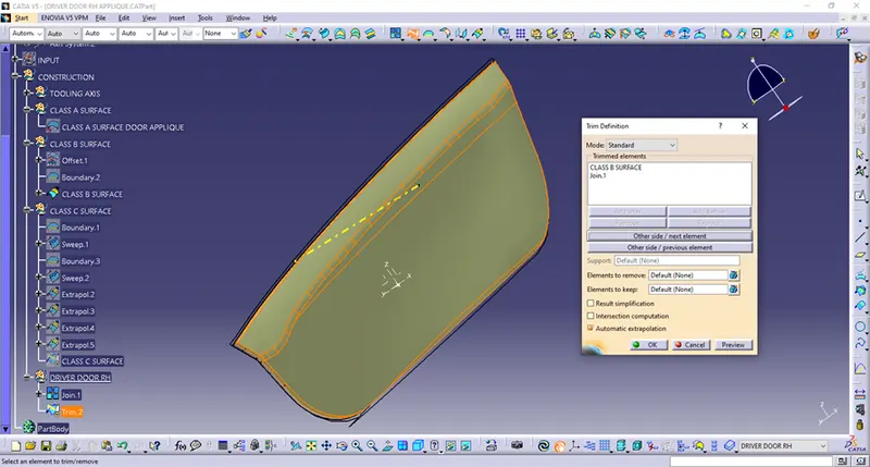
At the end,I get a closed surface,that I will rename as a DRIVER DOOR RH.
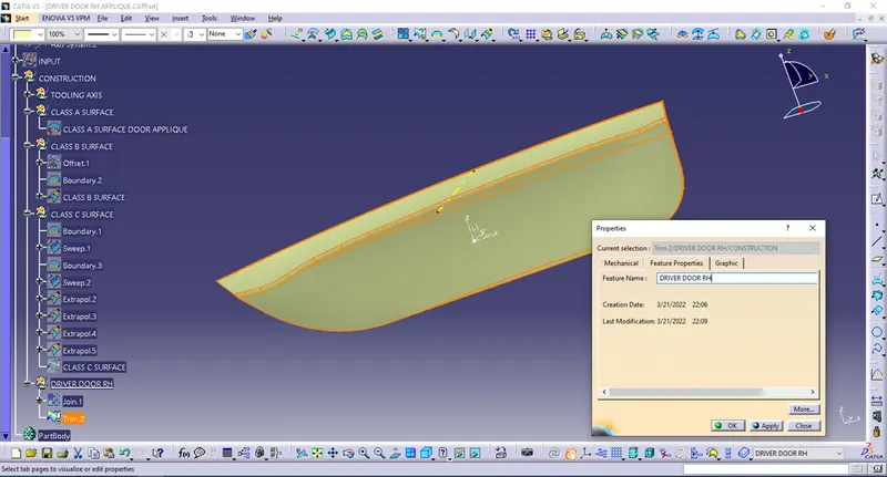
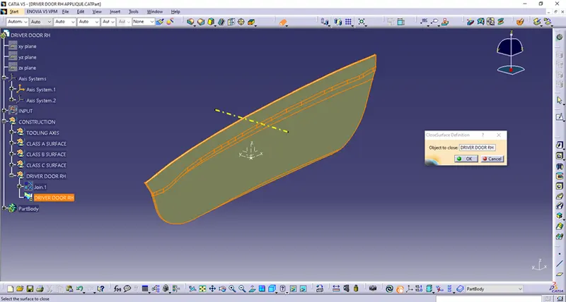
I will now close surfaces DRIVER DOOR RH in Part Design Workbench,under Part Body and rename a Part Body as DRIVER DOOR RH.
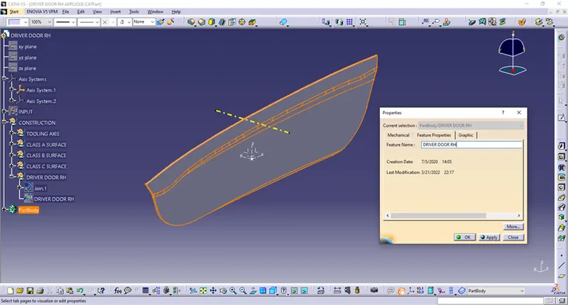
As a final check I will make Draft Analysis for a CLASS A SURFACE and a DRIVER DOOR RH solid part.
Draft Analysis CLASS A SURFACE – with that TOOLING AXIS shows all is done good.
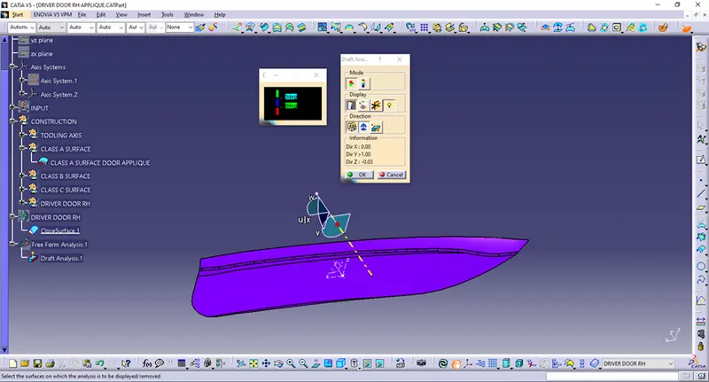
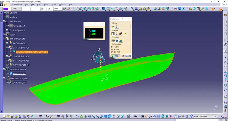
Draft Analysis DRIVER DOOR RH for Solid Part shows
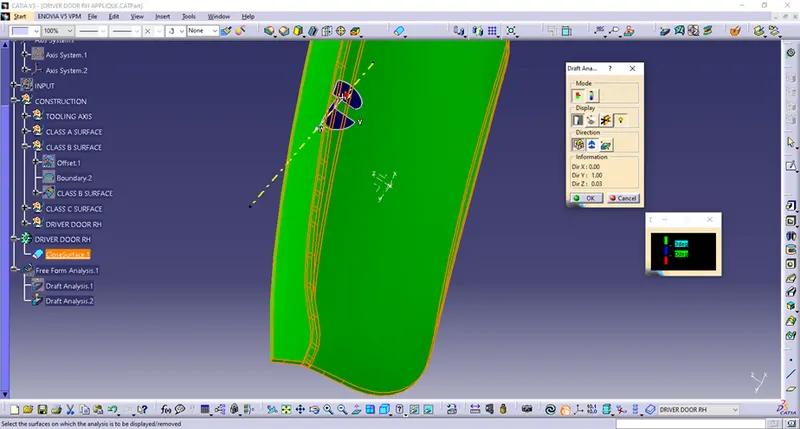
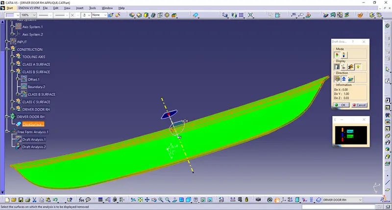
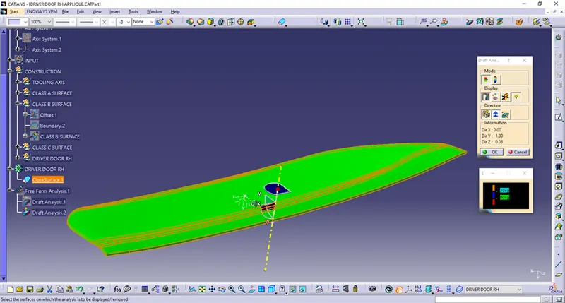
All required faces are with 3deg or more defined,so constructed TOOLING AXIS,CLASS A SURFACE,CLASS B SURFACE,CLASS C SURFACE and finaly solid Part DRIVER DOOR RH are good defined,the part could be manufactured regarding those requirements.
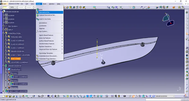
Now I am going to deal with 4 WAY 2 WAY LOCATORS and HEAT STAKES.That is why I am now inserting new Geometrical Sets with those names.
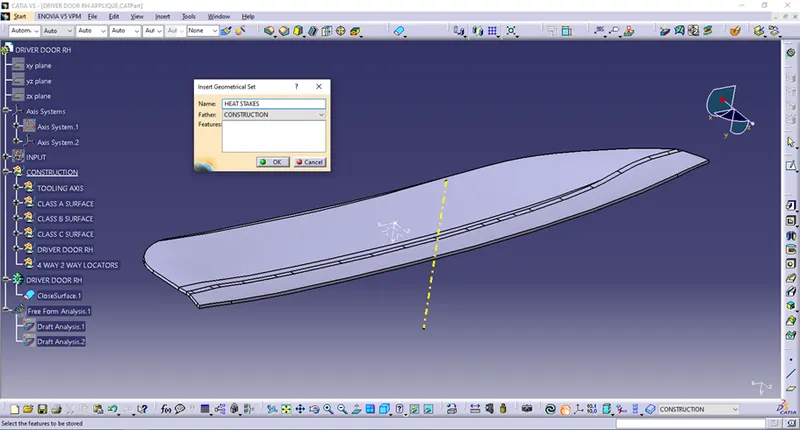
4 WAY 2WAY LOCATERS are features that should be done on plastic or composite components that have a function to hold the part on required position and unable moving in any direction (there are 6 degrees of movement,3 rotations and 3 translation and that features are holding components fixed).Those features are hidden,on the back side of the part,because of estethic and functional reasons (they are attached to other inner components).They are designed on the back side – CLASS B SURFACE,on the image bellow I want to represent where are they positioned (on CLASS B SURFACE) in correlation to other parts.
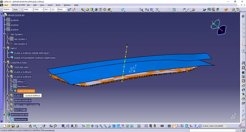
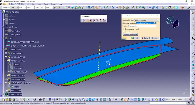
Now,I am going to extract CLASS B SURFACE and that extract will be my reference surface for 4 WAY 2 WAY LOCATORS and a HEAT STAKES.
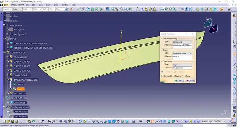
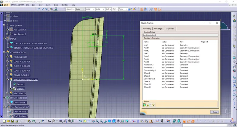
I am making sketches for a locators as follows.For fixation this part I need three locators (2 – 4 way and 1 – 2 way).
They should be done on much possible distance one to another to ensure good fixation and holding the part.
In order to have a solid part (I should thicken that sketch) I must insert new Body part.
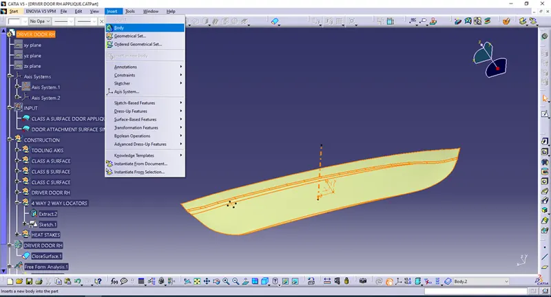
I have renamed a Body.2 as a 4 WAY 2 WAY LOCATOR.
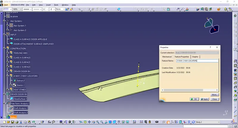
As I will be needed 4 WAY and 2 WAY locators separately I will insert few more Bodies and rename it as 4 WAY LOCATOR and 2 WAY LOCATOR later.
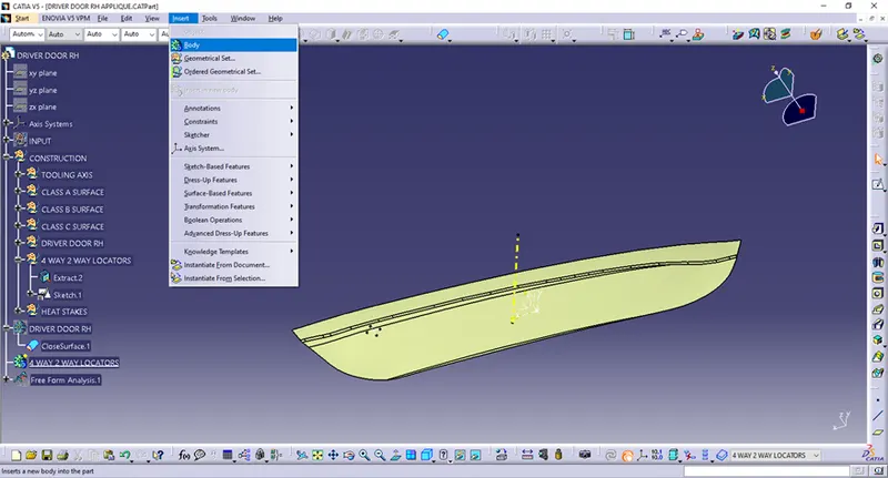
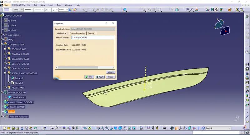
Now comes thicken to form a 4 WAY LOCATOR.
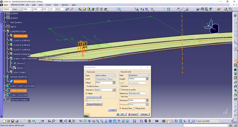
Locators are approximately 15mm high and it is important that all have approximately same value.
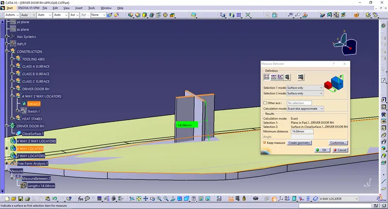
I am going to do 4 WAY LOCATOR on the other Side as follows.First I am going to Copy-Paste with link Feature and translate it.
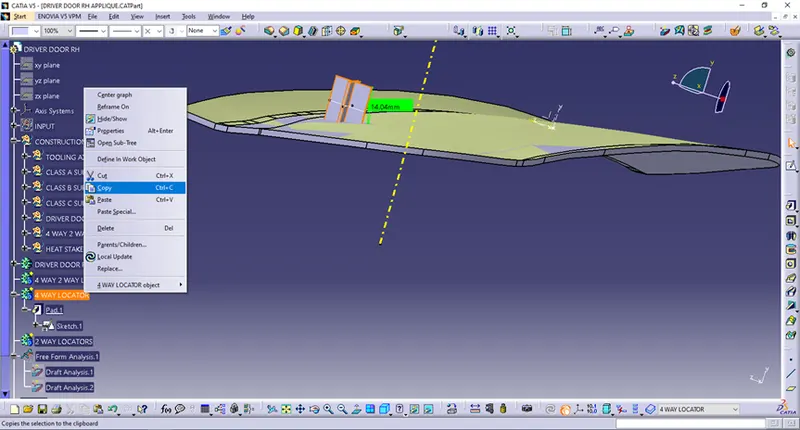
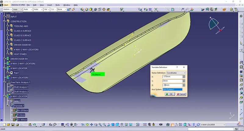
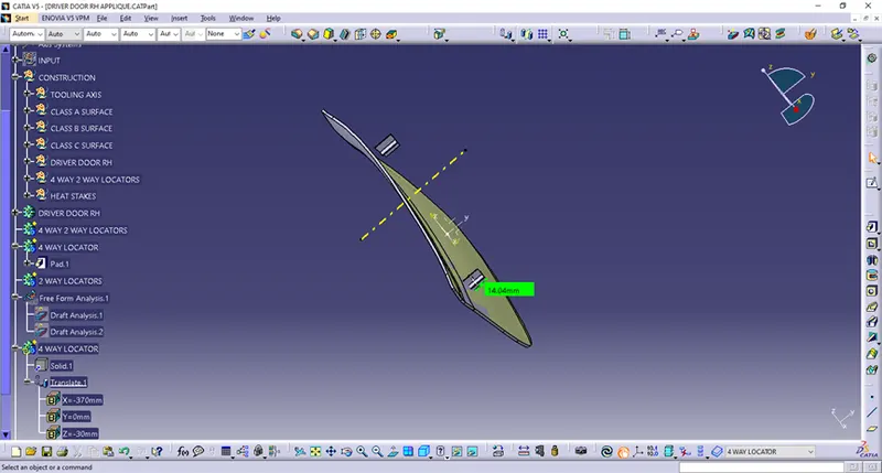
I am going to reposition Parent Feature 4 WAY LOCATOR.Afterwards I should translate pasted Feature in the Y direction,now is way above surface.
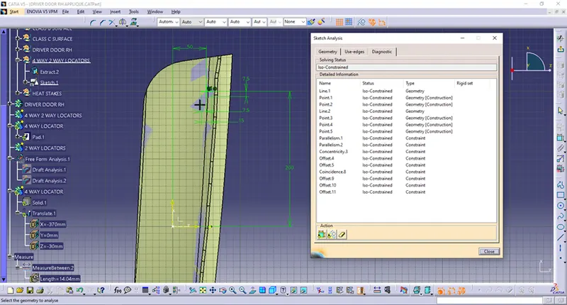
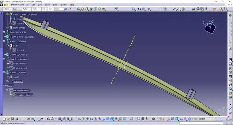
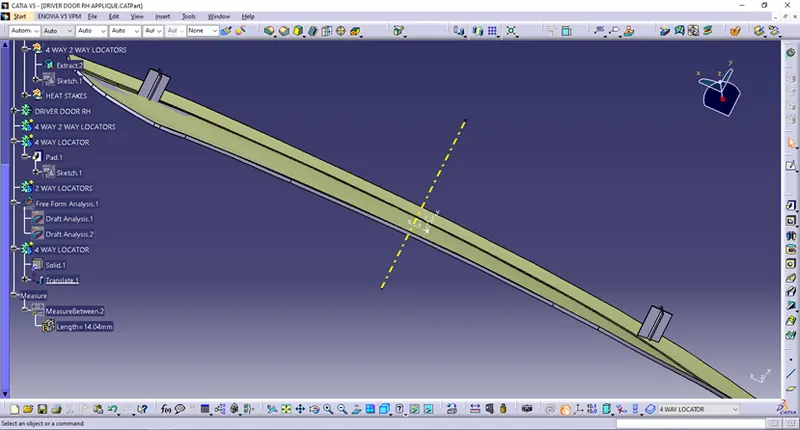
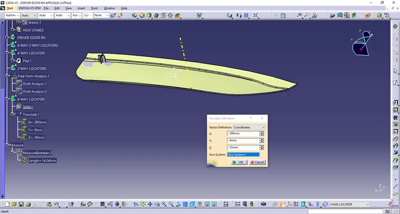
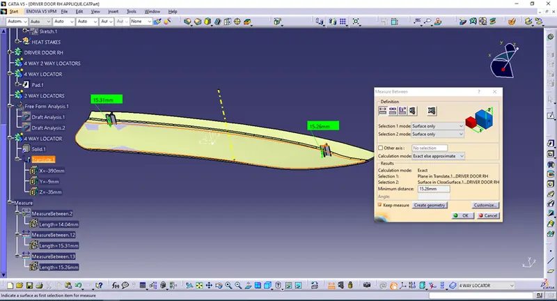
Locators are approximately same height and cca 15mm above the surface,that is what is required.
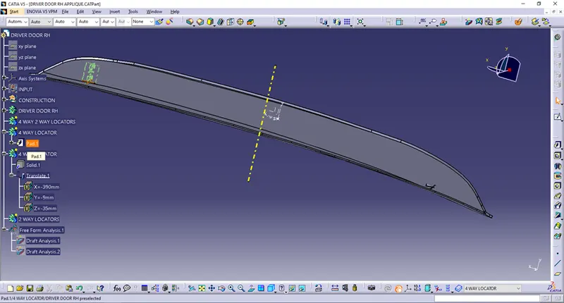
But now I see one problem...with so defined Pad (till Surface) on the right side I am getting nothing...I will change it a little bit (because of Draft also,that I am going to define now).
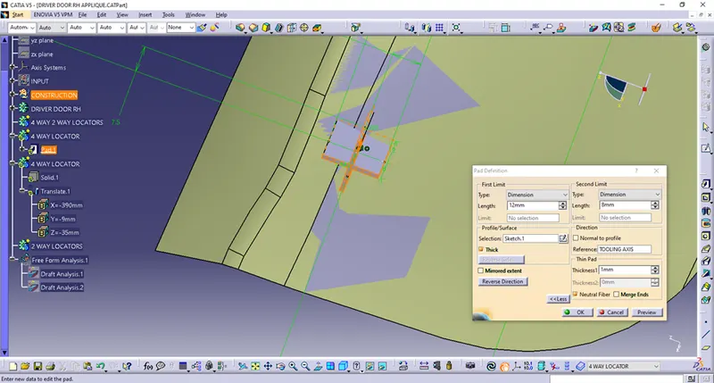
So is fine.
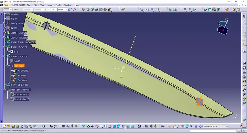
Now is time to deal with 2 WAY LOCATOR – as I have said it ensures positioning with 4 WAY LOCATOR in three points,triangle form,on the longest possible distance.Thickness of it is also 1mm (rule as for Ribs – 0.4mm x Part thickness to avoid sink marks).So,now I am drawing a Positioned Sketch under Geometrical Set 4 WAY 2 WAY LOCATORS and thickening it.
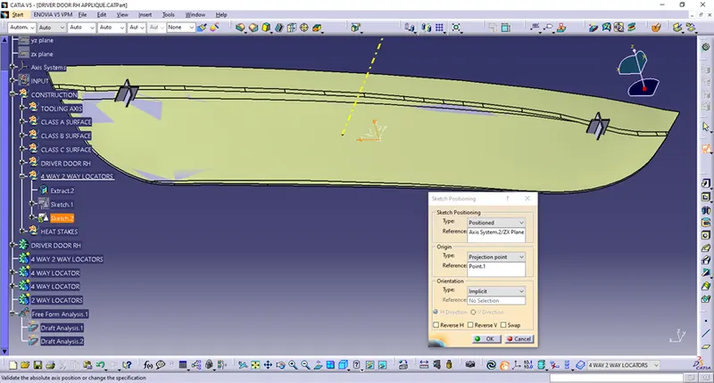
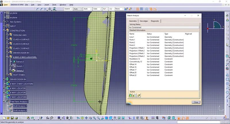
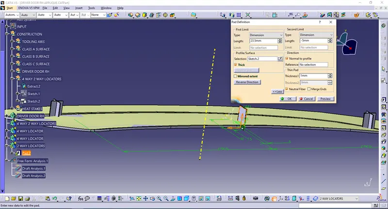
That is fine.I am now doing drafts,chamfers and fillets as follows.4 WAY LOCATOR,that is Pasted with link is upated accordingly.
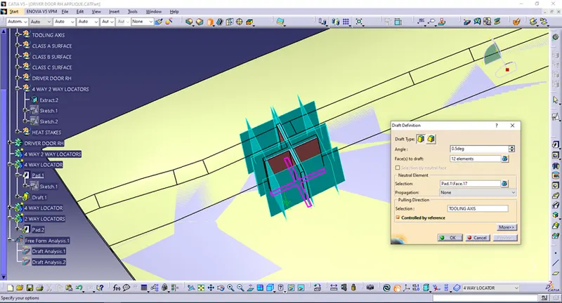
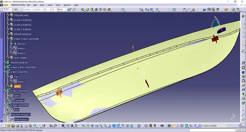
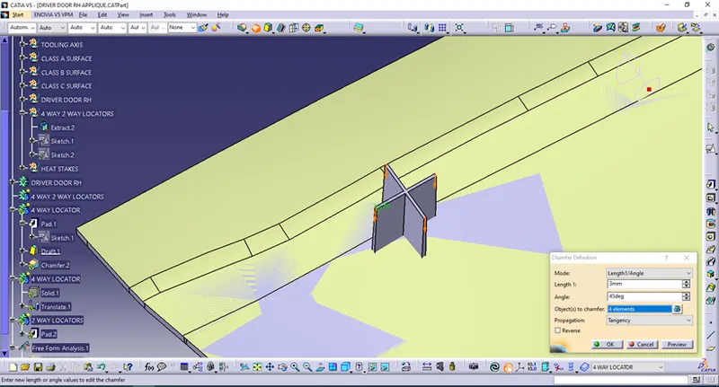
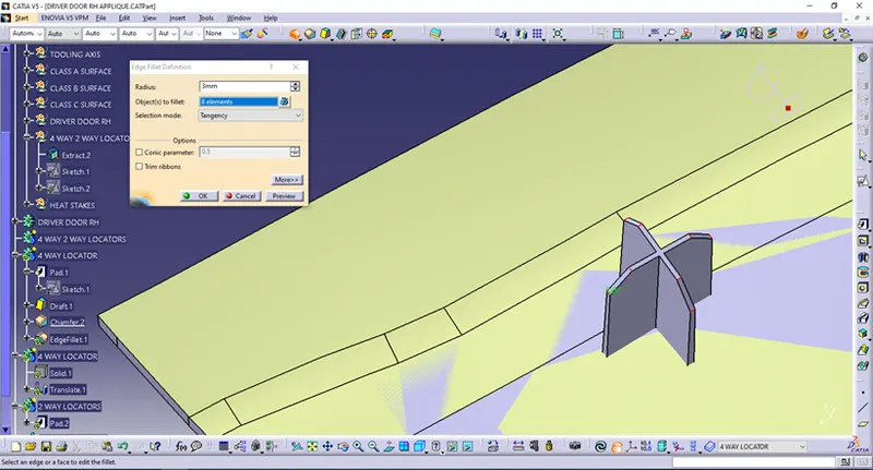
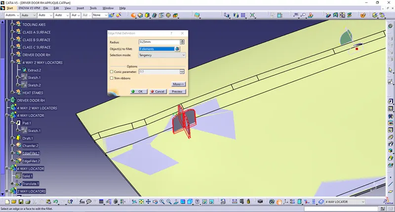
Now,I will do the same procedure for a 2 WAY LOCATOR.
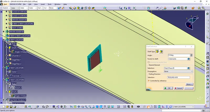
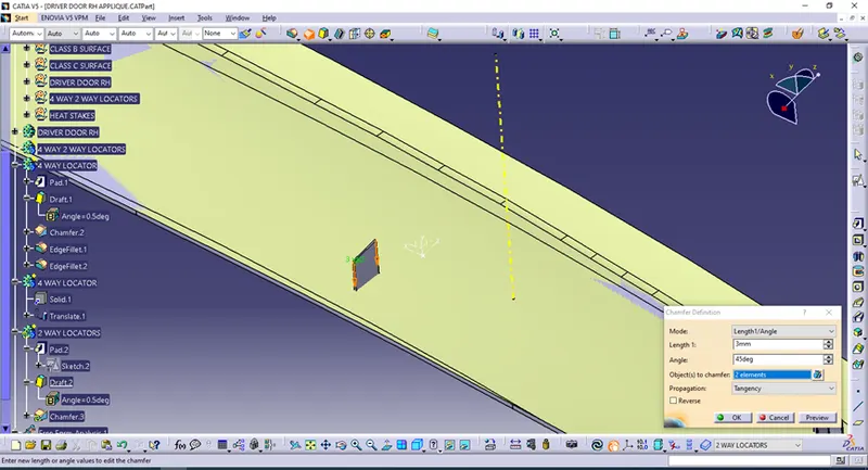
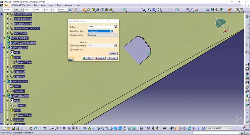
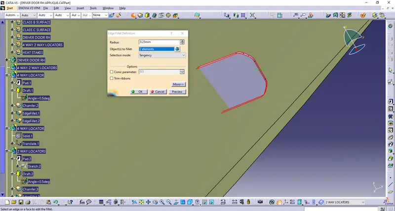
Now I will do the clearences for those fixing features.There is a rule – Clearence for a 4 WAY LOCATOR is cca. 0.1mm this is the first fixation point on which the Part is laid on (and those should be a little higher than 2 WAY LOCATOR ( cca 0.1 – 0.5mm) and a Clearence for a 2 WAY LOCATOR is cca. 0.5mm.
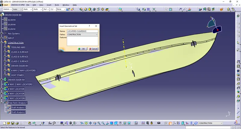
So,I will insert new Geometrical Set – LOCATORS CLEARENCE for those sketches.I will also check the height of this locators.
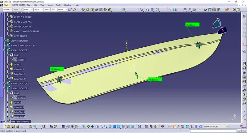
The locators heights are good defined.
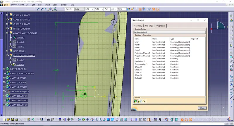
In the Geometrical Set LOCATORS CLEARENCE I will make a sketches as shown bellow.There I will Copy-Paste Locators sketches.
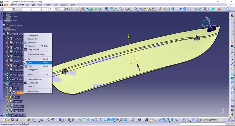
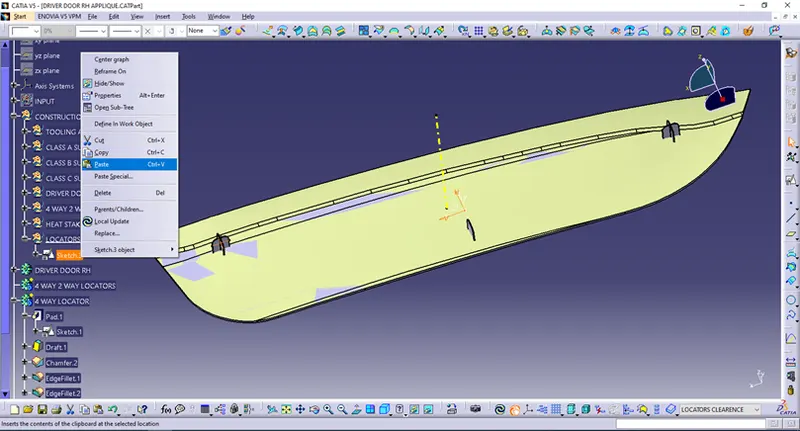
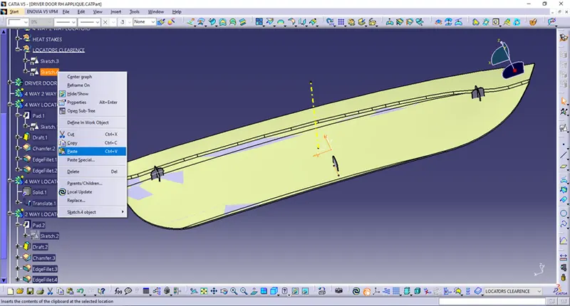
Those two sketches I have copied and the third clearence I will translate.It is translated as the feature.
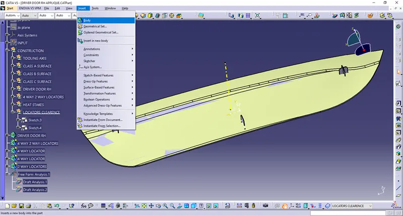
Then I am going to make a Features for clearences as follows.I should insert three new Bodies and rename it as 4 WAY CLEARENCE and 2 WAY CLEARENCE.
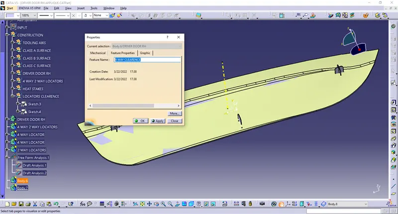
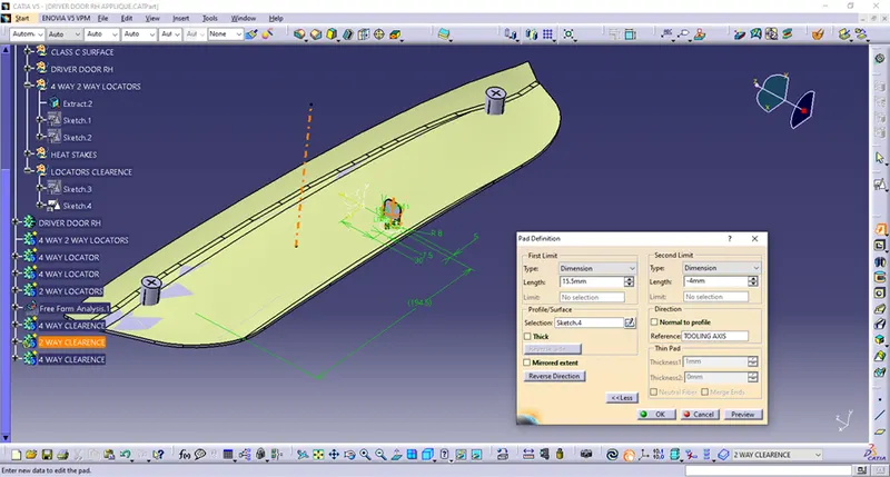
I have designed on the Sketches clearence features,following above mentioned rules for clearences.
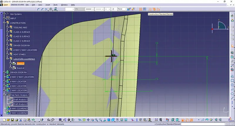
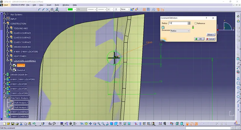
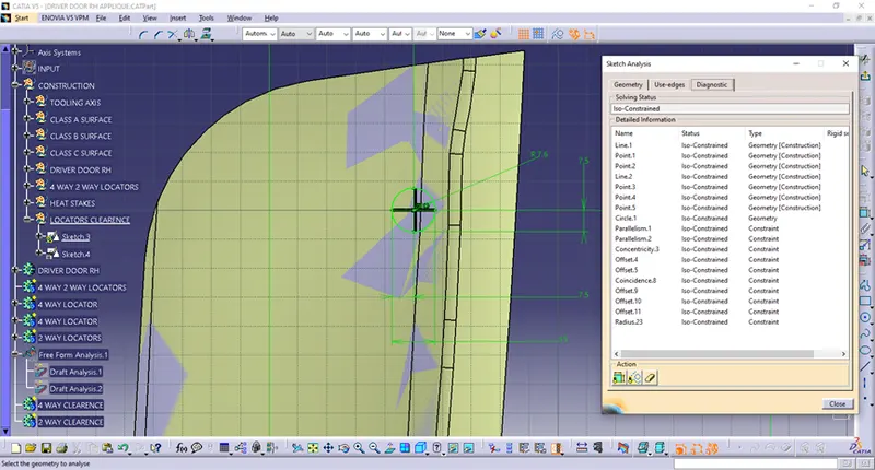
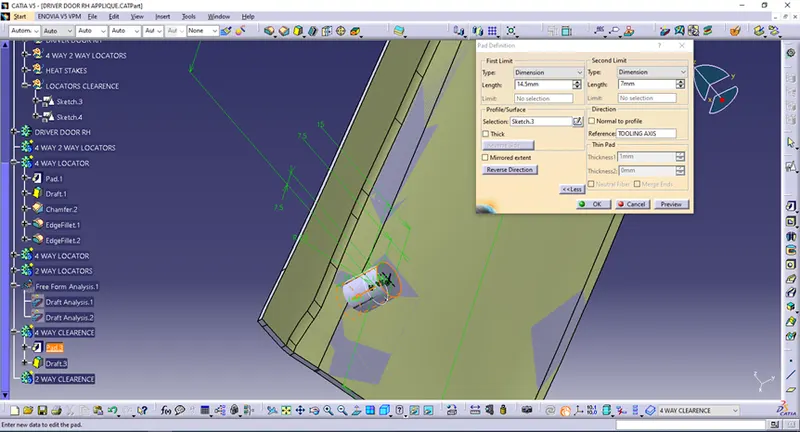
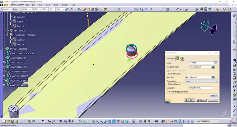
Then I am drafting 4 WAY CLEARENCE.
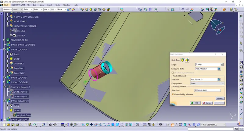
I have done Copy-Paste and translating that 4 WAY CLEARENCE.
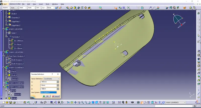
I will do the same procedure with 2 WAY LOCATOR (clearence here is 0.5mm).
Now comes Draft.
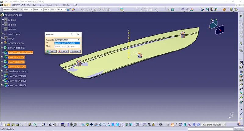
I have assembled those locators.
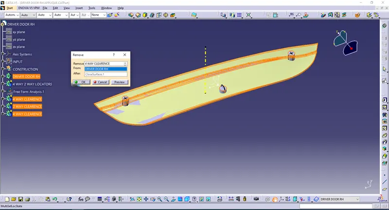
And then from that assembly removed clearences.
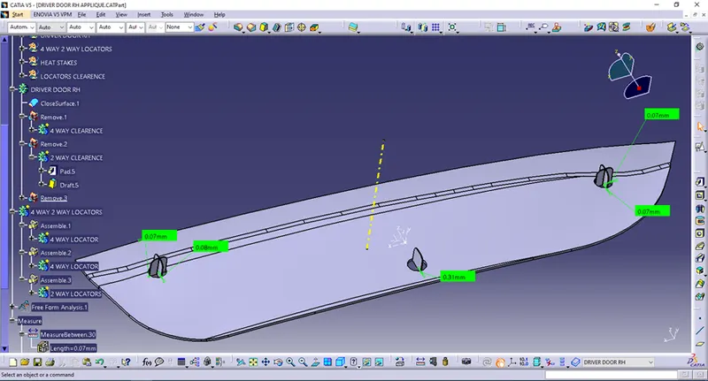
After I have done that I have chekced clearences.Bellow are results,it can be seen from it I should adjust it a little bit.
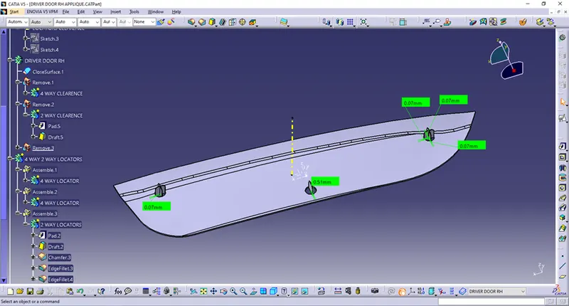
After adjustment I have got following results (clearences values are 0.1mm and 0.5mm) – this is satisfactory.
HEAT STAKES are features used to join plastic parts with other parts on the vehicle.They are so designed so,that under pressure and heat they are melting and form firm conection between the parts.Diameters for HEAT STAKES are not so firmly defined,they depend on the size of part,function,type of material.However,wall thickness of the HEAT STAKES should be 0.4 x Part thickness to avoid sink marks on joints.I have inserted Geometrical Set HEAT STAKE.
Heat stakes are mainly designed on distance at least 15mm from the edge,I have enough space here,so I will follow the rule.
I am making two curves as shown bellow.
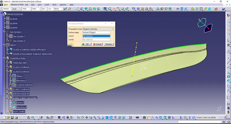
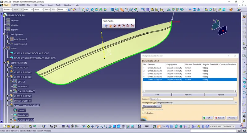
Then I am going to make two paralel curves to those and I will use extracted CLASS B SURFACE as a support.

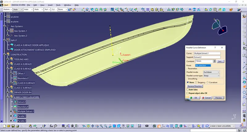
I am making equidistant ponits on those curves as shown bellow.Distance between this features should be at least 150mm.So I am measuring length of the parallel lines to determine how many HEAT STAKES should I make.
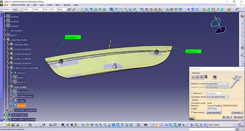
Length 516.42mm – 4 HEAT STAKES and length 618.17mm – 5 HEAT STAKES.
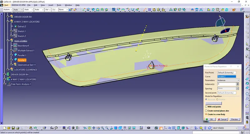
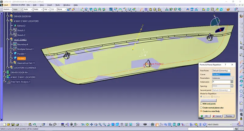
As it can be seen,with 5 equidistant Points on Reference curve,Heat Stake comes to close to 2 WAY LOCATOR,that is why I will increase the number of points and when it is so defined,it gives better result.
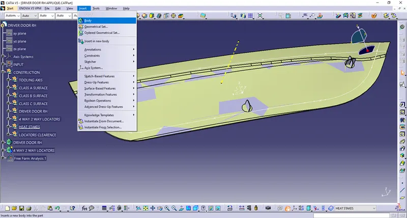
Then I am inserting new Body Part and renaming it as a HEAT STAKE.
I am drawing Sketch for it,as I already said,diameter holes are dependent of tools for joining,art of material etc.,but wall thickness should be 0.4 x Part thickness.One important thing is – height of HEAT STAKE,it must be lower than height of LOCATERs.The Part should be first fixed with Locators and then joined with Heat Stakes.
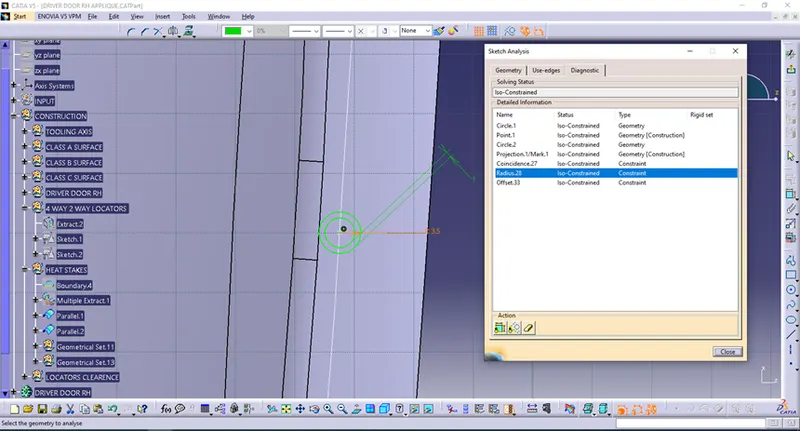
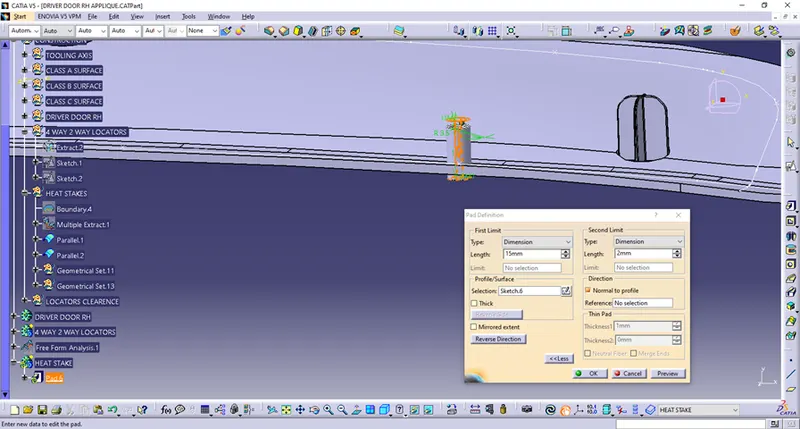
I will check the height of the feature – it should be lower than locators height.
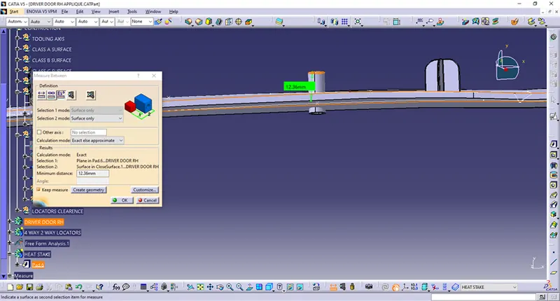
So is fine.
There is 10 HEAT STAKE features – I should Copy – Paste with link 9 features.
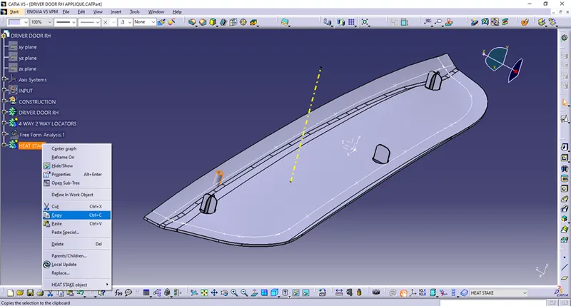
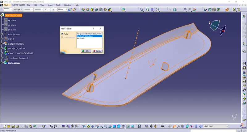
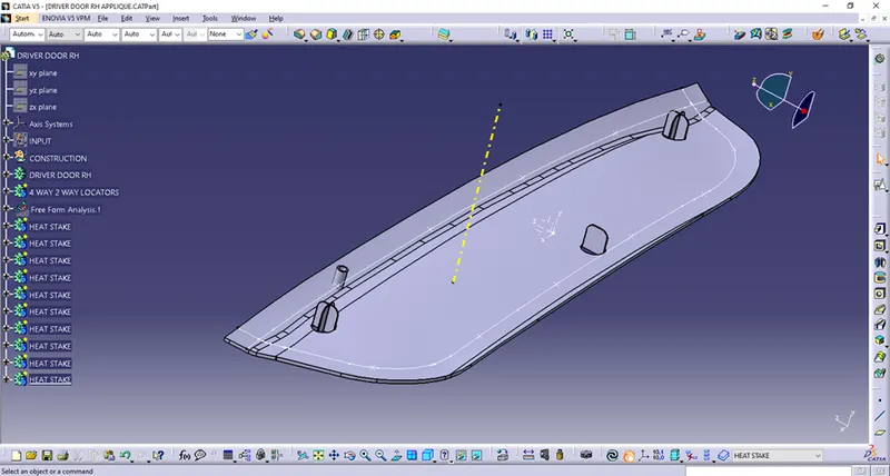
I am now translated features with Point to Point option.
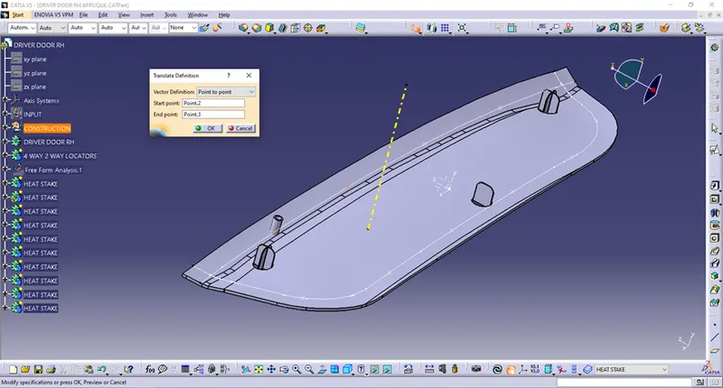
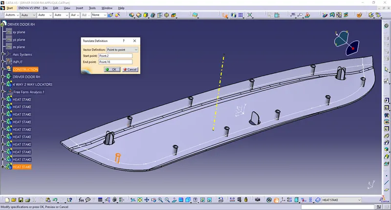
I will check height of those HEAT STAKEs.
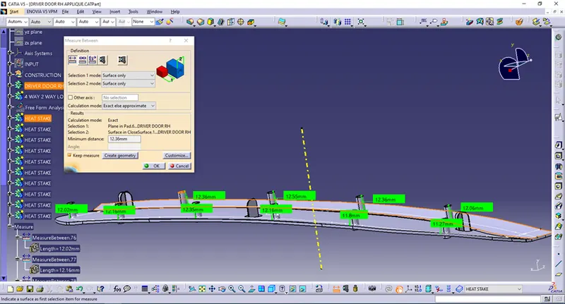
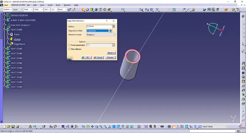
Features heights are good,I can go further,I am going to make a Draft and Fillets on Parent feature – it will be updated no all copied features.
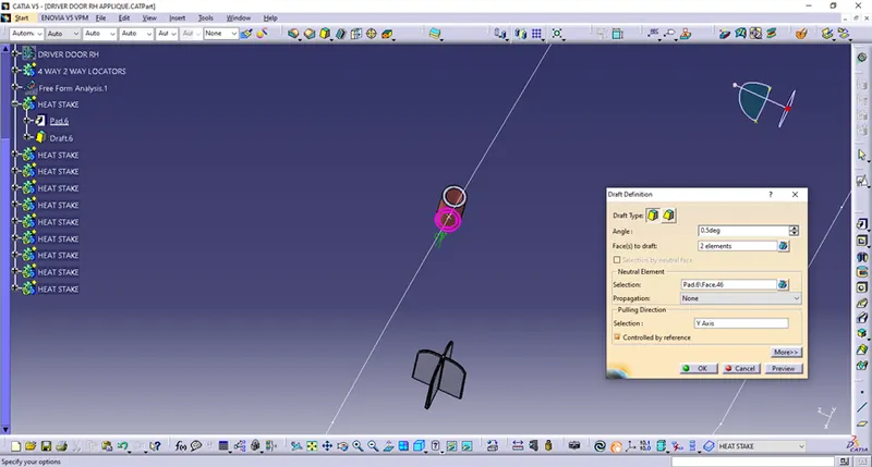
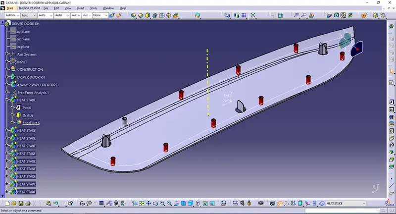
I am going to add 4 WAY 2 WAY LOCATOR features to main feature DRIVER DOO RH.
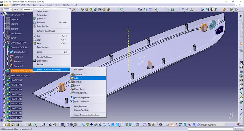
Then I am inserting new Body Part where I will be adding all HEAT STAKE features.I wil rename it as HEAT STAKES.
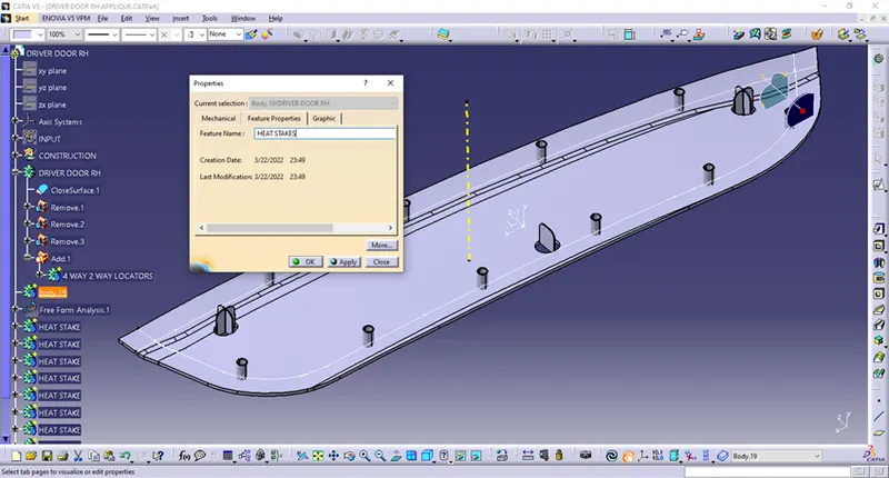
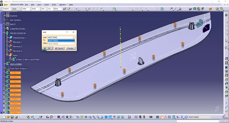
I will add HEAT STAKES feature with Union Trim to main Assembly DRIVER DOOR RH.
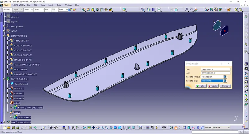
At the end I am going to fillet HEAT STAKES with 0.25mm.
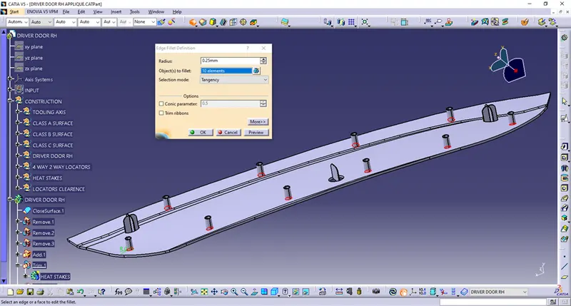
Finally,I am getting my DRIVER DOOR RH Part with all necessary features.
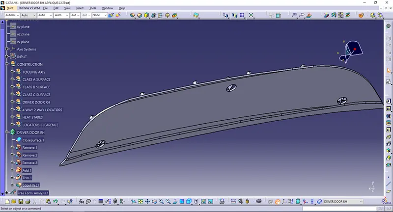
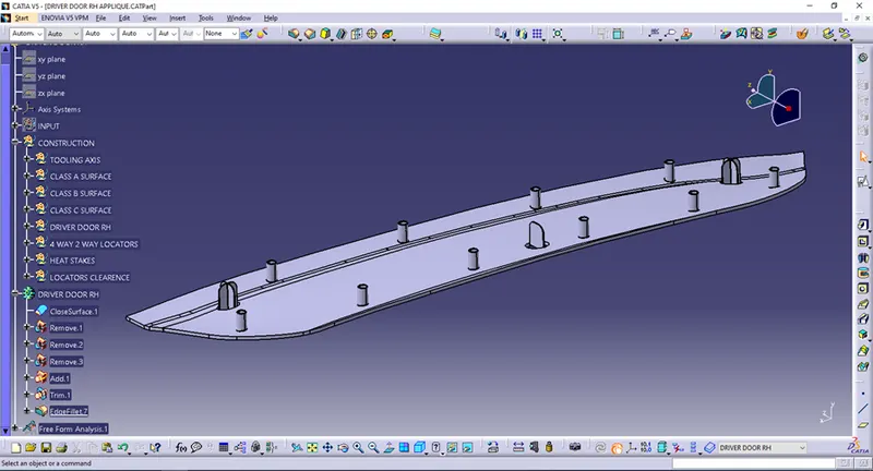
That is all fellows.
Best regards,
Ivan Tole