Week 9 - Project 1 - Door Applique Design with Engineering Features
DOOR APPLIQUE DESIGN WITH ENGINEERING FEATURE
AIM- Door Applique Design with Engineering feature. Create 4-way locator and 2way locator and heat stacks.
OBJECTIVE- Create Door applique plastic component using Class A surface. To begin with tooling axis creation and draft analysis of class A surface.
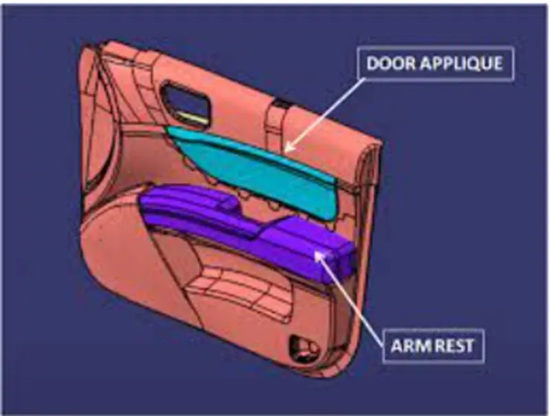
Created Heat stakes and locators considering the design rules of industry required.
INTRODUCTION-
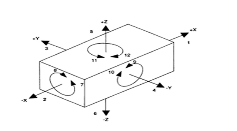
3-2-1 PRINCIPLE- A workpiece free in space can move in infinite number of directions. For analysis this motion can be broken down 12 directional movement or degree of freedom. All 12 degree of freedom restricted to ensure proper referencing of a work piece.
Below image shows that all 12 degree of freedom all related to central axis of the workpiece. There are 6 radial degree freedom and 6 axial degrees of freedom. The axial degree of freedom permits straight line movement in both directions, along the main 3 axis X, Y &Z. The radial degree of freedom permits rotational movement, both clockwise and counter clockwise radial direction around all 3 main axes.
LOCATORS-
PRIMARY LOCATOR- First the 3 locators or support are placed in the workpiece. It will be positioned on the primary locating surface also known as datum. It will resist 5 degrees of freedom.
SECONDARY LOCATOR-The next two locator are normally placed on the secondary surface restricting 3 degrees of freedom.
TERTIRY LOCATOR- This locator is positioned at the end of the part. It resists 1 degree of freedom.
2-WAY LOCATOR- A 2 way locating pin restricts motion along 1 axis (or 2 degree of freedom) like a round pin in a slot.
4-WAY LOCATOR- 4way means prevent movement at 2 axes. (+X, -X, +Y, -Y) on the plane. Generally, you have cylindrical pin on the fixture and circular hole at workpiece part.
HEAT STAKES- Manufacturing operations currently use many different combinations of attachment methods to keep components together. Common fasteners such as bolts, screw, and rivets can be used to form permanent attachments, but there are attachment methods that don’t require secondary hardware. One of those methods is heat staking which does not require additional fasteners.
Heat staking is the process to attach two separate component together secondary component. It’s a permanent attachment method that doesn’t require any additional material such as adhesive or a solvent to make the permanent bond. The only addition is the heat applied to melt the plastic and tool to shape the plastic to form the mechanical connection.
Heat staking is a great option that is comparable in strength and durability to other operations involving secondary fasteners without extra cost. These connections can also resist corrosion in harsh environments.
REASONS FOR HEAT STAKING-
- Multiple staking shapes for different benefits.
- Excellent durability
- No extra materials are needed
- Increased efficiency
- Easy maintenance.
PROCEDURE-
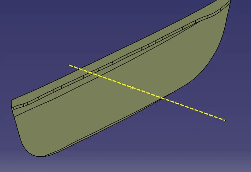
First, we check the continuity of the surface by join or boundary command. Next check from all the direction which is perfect for creating tooling axis. As that is flat surface so we create a point using on surface at 0mm. and y direction draw a simple line that is our tooling axis.
CREATED SOLID COMPONENT OF CLASS A SURFACE-
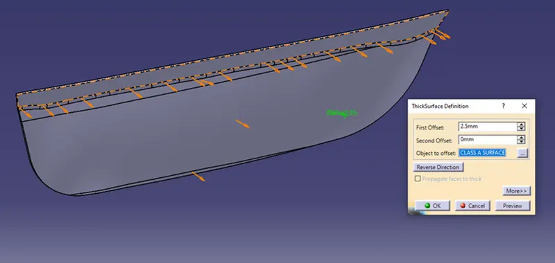
We created solid component by thickening of class A surface up to 2.5mm using thick command in part workbench.
CREATE LOCATORS CONSIDERING DESIGN RULES-
4-WAY LOCATOR-
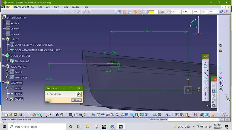
First of all, we create a positioned sketch the rib should be created intersecting and iso constraint.
Pad the sketch thickness of 1.3mm in neutral fiber. And giving draft 0.5 degree also giving chamfer 3mm and edge fillet of .3mm.
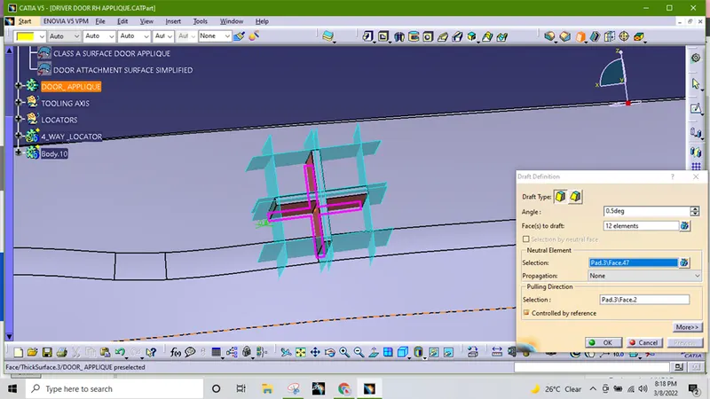
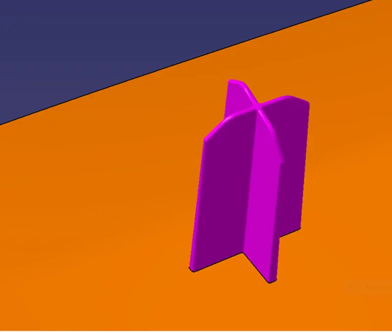
We need to make another same 4-way locator in other coordinate. Copied it and paste in special (result with link). Translation it on X=-400, Y=-11.5mm, Z=-37 mm
2-WAY LOCATOR-
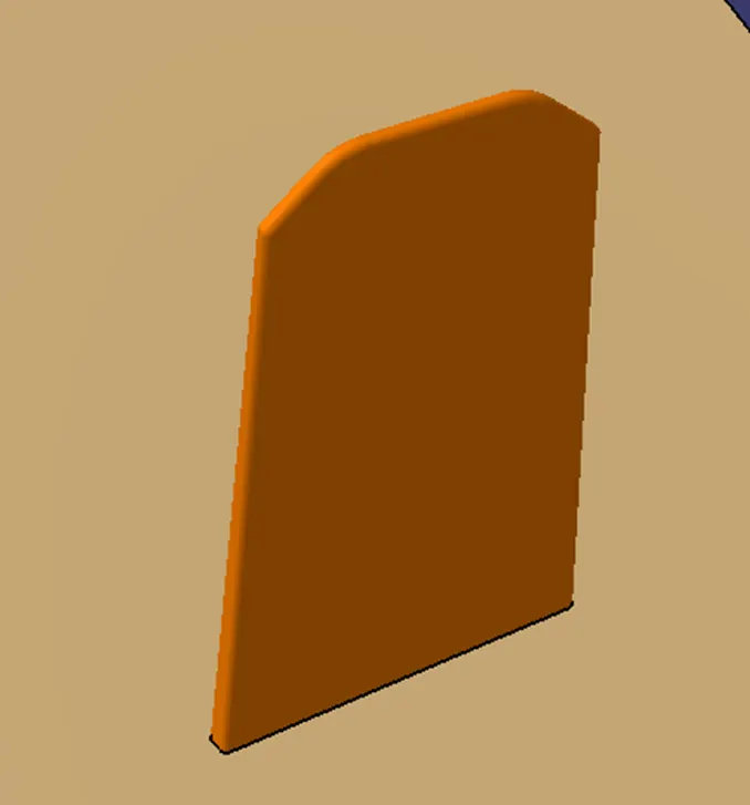
For this we create single rib and constraint it.
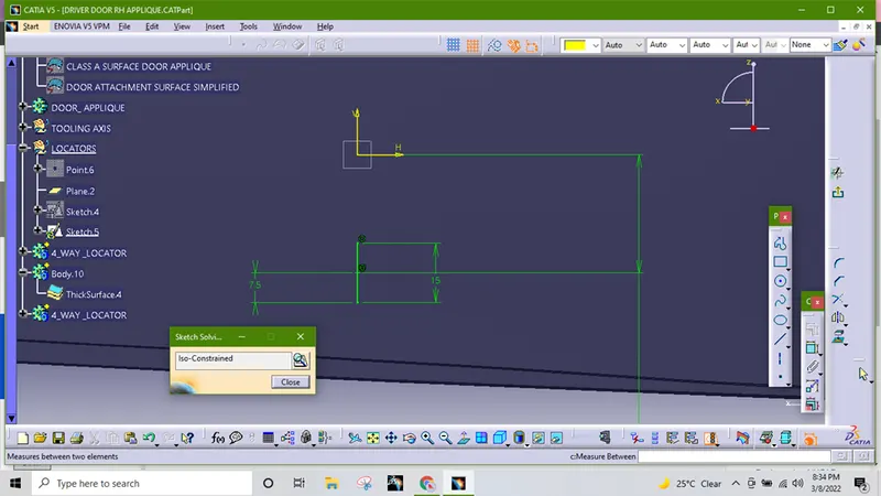
Pad it of thickness of 1.3mm. Giving draft 0.5degree and opening chamfer is 3 mm*45degree and fillet .3mm.
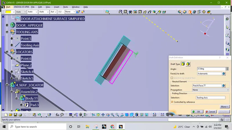
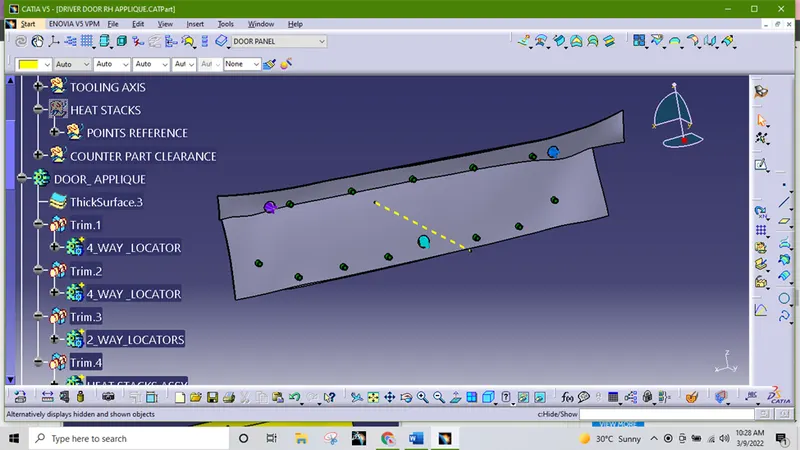
Make sure the pad extended through the solid body. After that perform union trim with door applique.
HEAT STAKES-
Since there are several heat stakes to create to create each that consume time.so we do translation operation to locate the stakes. To assemble with main part.
- Extract the upper and lower surface of class A and offset it 2. 5mm.Then parallel curve it by minimum of 15 mm.
- After that make a point on the boundary by point and plane reptation command.
- For upper boundary instead of 5 and lower boundary 7 at the constant of 15mm.
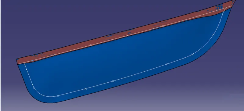
Make sure the heat stakes are not interfacing on ribs and locator.
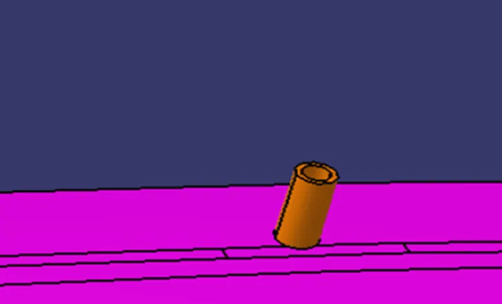
To create heat stack, go to sketcher workbench and create two circles of 7mm and 5mm diameter.
After that pad the sketch. And draft it to 0.5degree.
TRANSLATION-
First the boundary curved is extracted and this curve is parallel to 15mm. Create the repetition of points instances as required.
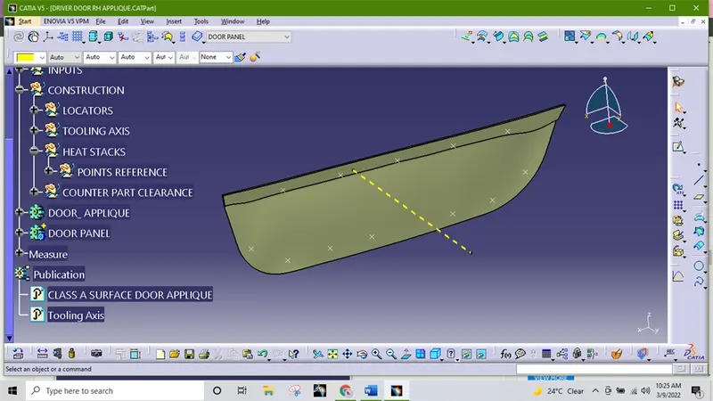
Now copy the heat stack and again paste it and then use translate by a point on this copied heat stack. Assemble all heat stack at body and later assemble them with door applique by union trim.
MAKING THE HOLE ON DOOR ATTACHMENT COMPONENT
To show the assembly of door applique and door panel we need to create counterpart clearance to the heat stack and locator follow the step below-
- Make a sketch of the clearance of heat stacks 0.1clearance and each time clearance 0.5mm for locator that is R8 for heat stack and 14.9 for locator.
- Pad it and given the draft angle of 0.5degree for locator
- Transfer it on each heat stack and locator respective
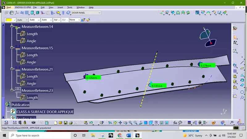
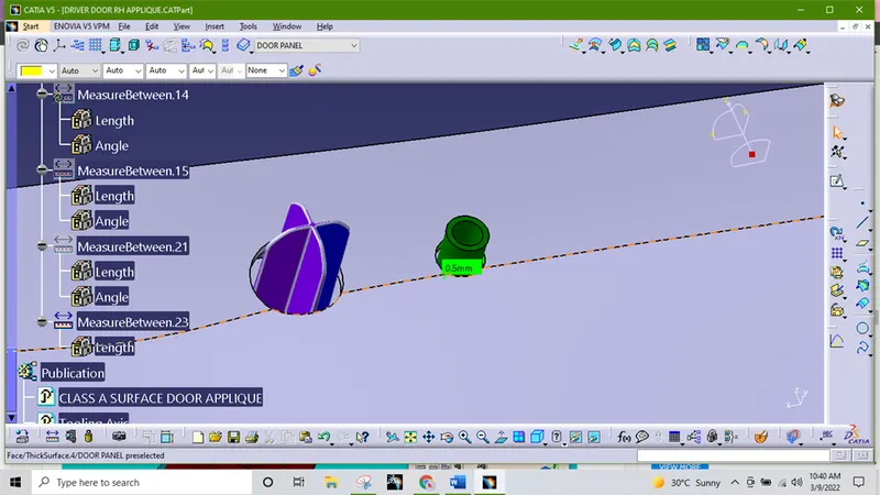
Then remove it from door panel using Boolean remove operation.
DRAFT ANALYSIS-
- Final plastic parts are the nominal draft angle is 3 degrees but even 7degree is allowed for the subassemblies like ribs and slots.
- Insert< Analysis< Feature draft analysis
- First the compass is moved to the part which used to define the tooling axis new current draft direction then lock the draft direction using the lock icon.
- The color of the chart indicates the draft if the color is indicated that means the part passes and used for further operation.
- By using the analysis under the running point icon, we can check draft angle at the various surface of the component.
- If the surface satisfied the draft angle, then it shows the green color if not appears in red color.
CLASS A SURFACE DRAFT ANALYSIS
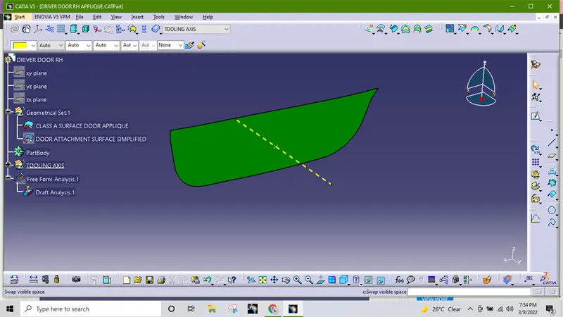
DOOR APPLIQUE DRFAT ANALYSIS
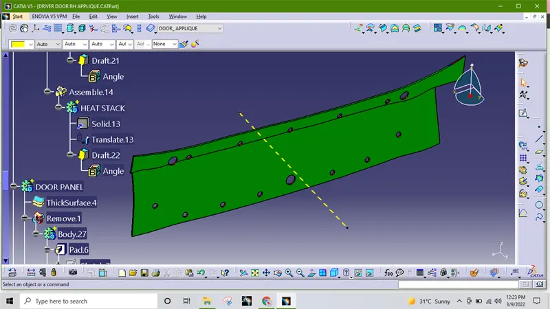
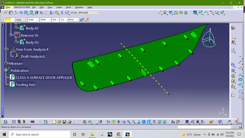
TREE
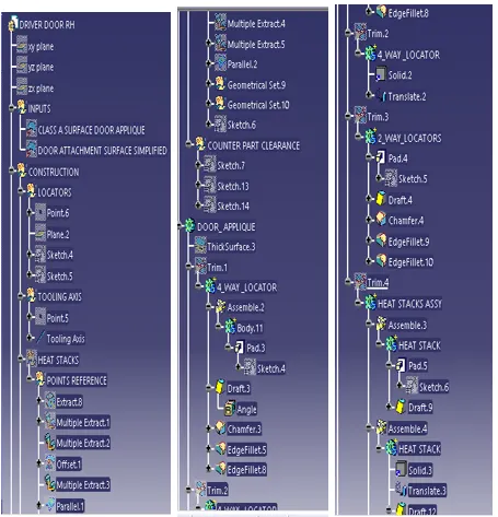
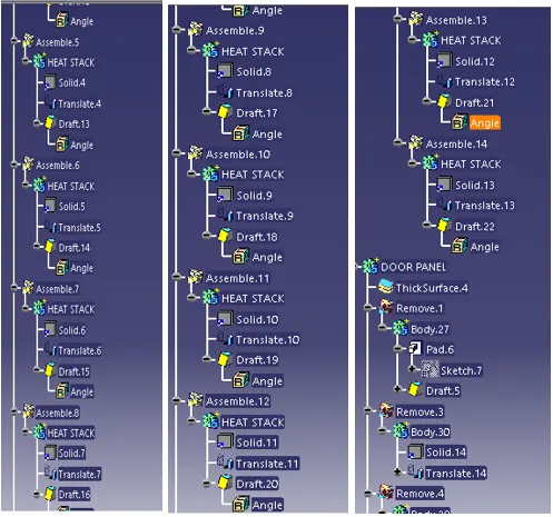
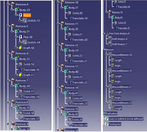
DESIGN VIEW
ISOMETRIC VIEW
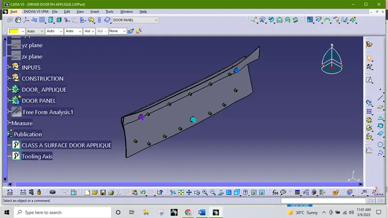
FRONT VIEW
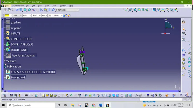
RIGHT SIDE VIEW
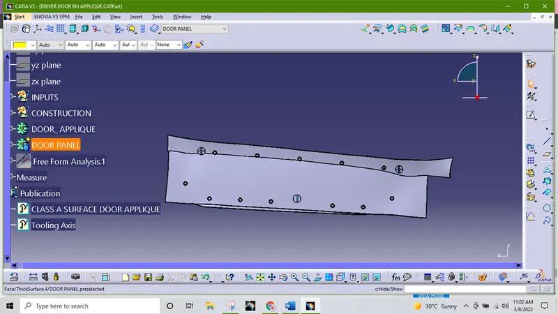
TOP VIEW
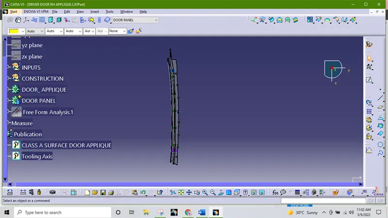
CONCLUSION-
Door applique is developed by given class A surface.
2way and 4 wat locators have been designed in order to fix the position with the applique with the door panel and also designed the heat stacks and locator which used to fix the component.