Week 9 - Project 1 - Door Applique Design with Engineering Features
WEEK-9
CHALLENGE-3
AIM
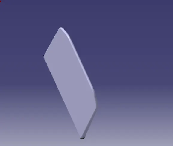
To create the solid bodies from the given class-A surfaces of Applique and Door surface and add the features like heat stakes and locators for the assembly of these two bodies.
THEORY
Locators
Locator pins are usually used to locate a workpiece on a fixture or to align two fixture pieces. Every component has 12 degrees of freedom (6 translational plus six rotational). The 11 degrees of freedom other than the line of fixation must be arrested before fixing the component. The locator pins are classified into two types based on the degrees of freedom: 2-way locator and four-way locator pins. As the name suggests, the two-way locator pins restrict the motion in two directions and the four-way pin in four directions.
Heat staking
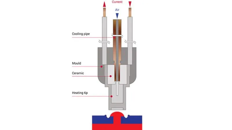
Heat staking, also known as thermoplastic staking, is joining two dissimilar materials together. In heat staking, local heating and cooling are used to raise the temperature of plastic components and allow plastic reforming to be carried out. This reforming can be used in a wide variety of applications. The plastic feature used for this process is called Heat stakes.
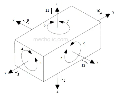
3-2-1 principle of location
The 3-2-1 principle of location (six-point location principle) is used to constrain the movement of the workpiece along the three axes XX, YY, and ZZ. This is achieved by providing six locating points, three pins in the base plate, two in the vertical plane, and one in a plane perpendicular to the first two planes.
In this method, 9 degrees of freedom are controlled.
Pins A, B, C on the base plane (a plane parallel to the plane which contains the X and Y axis) restrict the rotation of components about the X-axis and Y-axis. It also limits the downward movement of the component along the z-axis. I.e., 1,2,3,4 and 5 degrees of freedom are restricted. Pins D and E are parallel to the plane containing X and Z axes. It prevents the rotation of components about the Z-axis (6, 7 degrees of freedom) and the body's movement along the Y-axis towards one direction (8 degrees of freedom).
The last pin, F, is parallel to the plane containing Y and Z axes. It restricts the movement component along X-axis in one direction. The three remaining degrees of freedom 10, 11, 12 are unrestricted. It facilitates the loading of the component in the fixture. These three degrees of freedom may restrict after loading the component by using clamping devices.
PROCEDURE
Evaluating the class-A surfaces
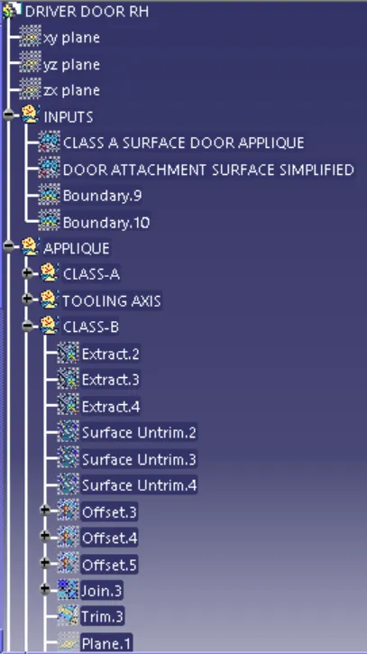
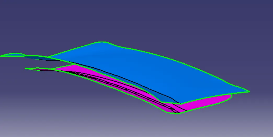
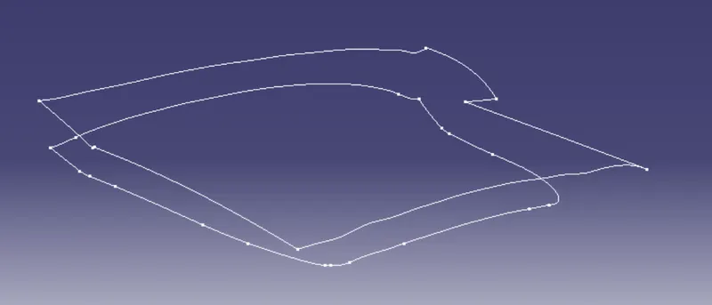
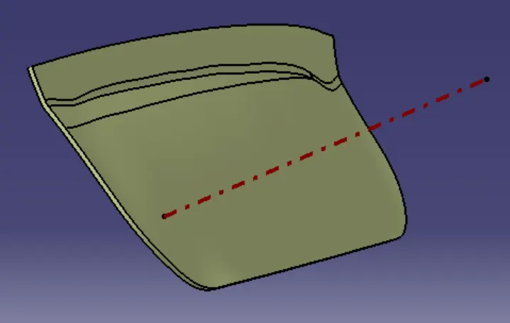
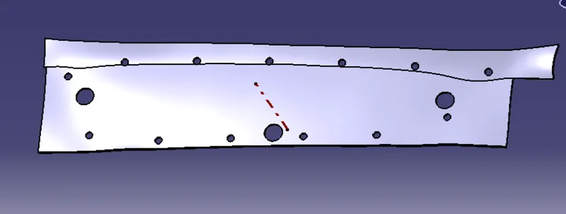
The given class-A surfaces of appliqué and door surface are checked using the JOIN/ BOUNDARY option. Any patches/ irregularities found are to be rectified/ reported.
Creating the tooling axis
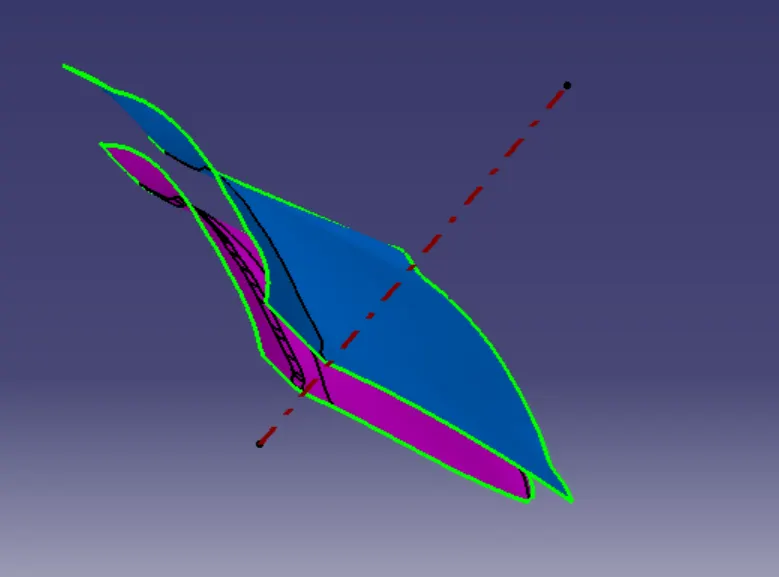
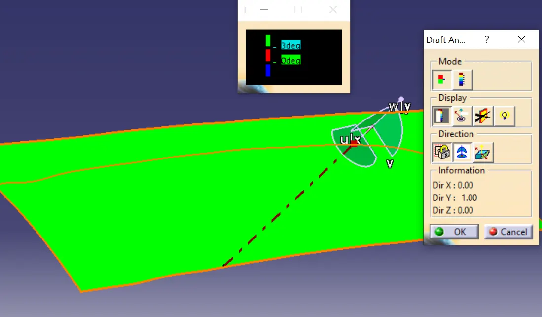
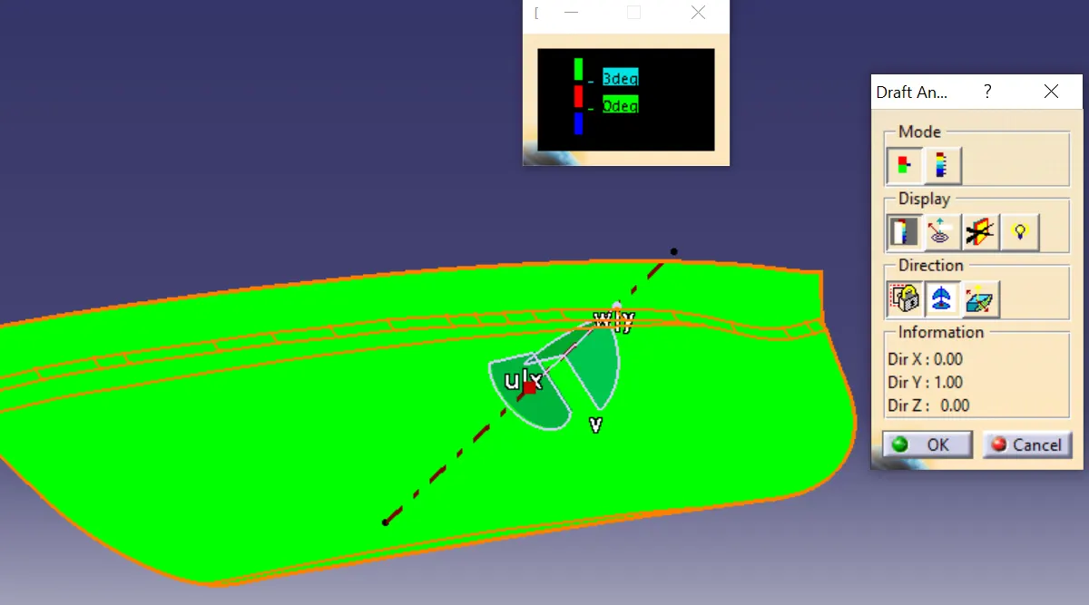
For the initial tooling axis, the Y-direction is taken by looking at the surface of class-A. Draft analysis is performed on class-A to verify this tooling axis.
Creating the B and C surfaces
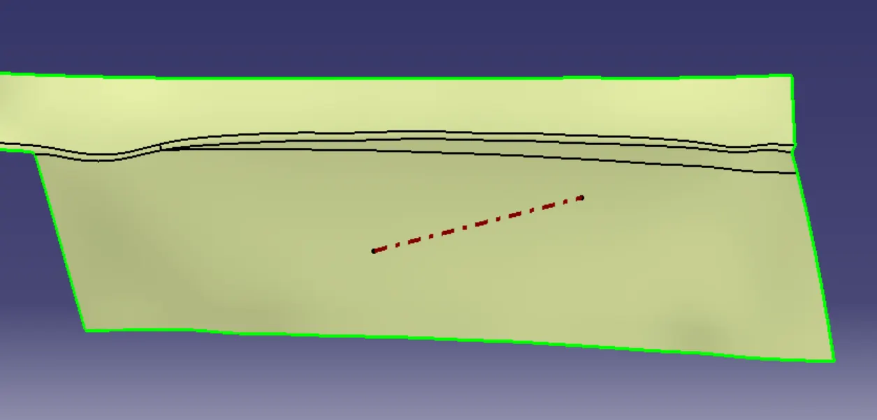
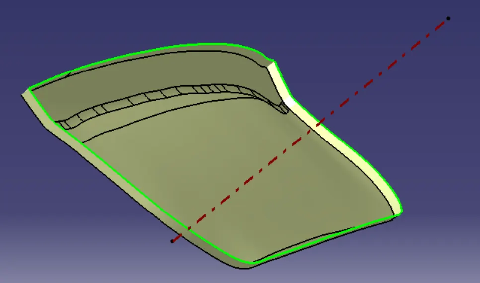
The A-surfaces without the fillets are extracted and untrimmed to get the original surfaces, and a 2.5mm value offsets these inward. These surfaces are extrapolated to touch each other properly, and the required faces are obtained by trimming these surfaces. For C-surfaces, the boundary of the A-surface is extracted using the sweep command. The faces are generated at an angle of 3 degrees to the tooling axis.
Finally, the C and A-surfaces are joined together and trimmed with B-surface to get a closed body. This surface body is now converted into solid using the closed feature present in the part workbench.
Creating the locators
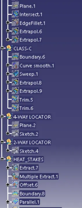
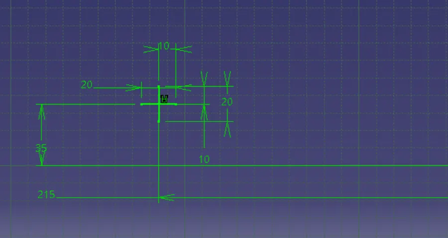
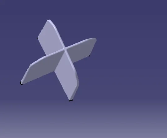
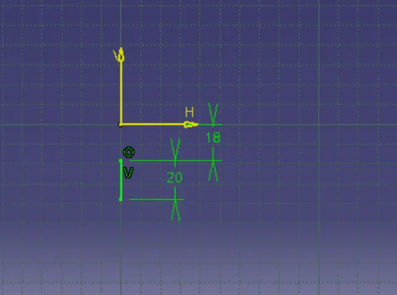
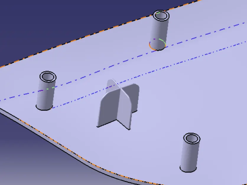
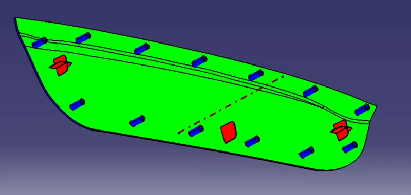
By following the 3-2-1 principle, first, we create three pins in the base plane. Two of them are four-way locator pins among the three pins used, and one is a two-way locator pin. These are created by sketching with two perpendicular lines for the four-way pin and a single vertical line for a two-way pin. These sketches are padded by required height, and a thickness of 1mm is given, and all the surfaces are drafted by 0.5 degrees with the tooling axis. A chamfer of 3mm is provided at the top surface's edge to ease the entry of the pin during the fixing process. These pins are joined to the main body using Boolean operations, and given values fillet the edges of the pins.
Creating heat stakes
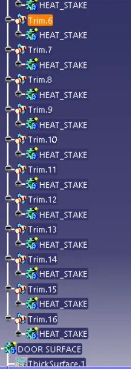
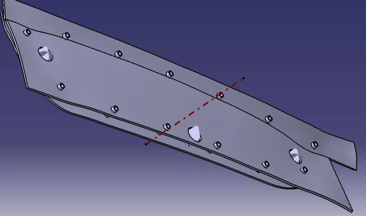
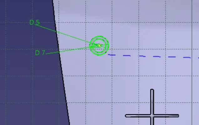
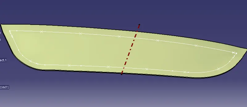
First, the class-A surface is offset by 2.5mm in the direction of the B-surface, and the outer edge is extracted. This outer edge is offset by a 15mm distance towards the center of the surface. The length of this offset curve is measured, and the length divided by 50 gives us the number of heat stakes that can be provided along this line. This line is now divided into portions, and the points are plotted to place the heat stakes. A sketch is created with inner-outer circles of diameter 5mm and 7mm, respectively, and this sketch is now padded, and the faces are drafted by 0.5 degrees with tooling direction to get a solid feature. This body is now added to the main body using Boolean operation. The same operation is done for every point, and the height of any heat stake must not exceed the height of the locator pins as it causes issues during assembly.
Providing clearance
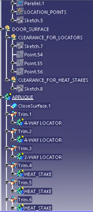
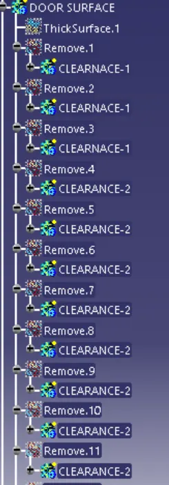
The holes for these locator pins and heat stakes to sit should be created on the door surface with a clearance value of 0.1mm from each side of the pin/ heat stake edge. Appropriate sketches are created and padded up to convert into a solid feature. These solid features are now joined to the door surface body, obtained by thickening the class-A by 2.5mm using the REMOVE Boolean operation to get the cutout portion in the door surface.
Draft analysis
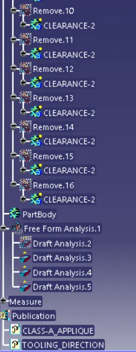
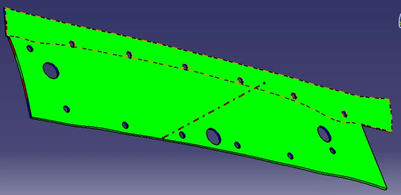
Draft analysis is performed on the final component to ensure the draft angle for all the surfaces in the assembly.
FINAL MODEL
Geometrical sets