Week 9 - Project 1 - Door Applique Design with Engineering Features
Door Applique Design with Engineering Features
Aim: - The aim of this report is to create the Door Applique Plastic component through the given Class-A surface, Locators, and Heat stakes considering the design rules in CATIAV5 (Computer-aided three-dimensional interactive application).
Objective: -
- To create the Door Applique Plastic component through the given Class-A surface.
- To create the tooling axis for the Door Applique model meeting the requirements of the draft angle.
- To explain the bisecting method used in order to create the tooling axis for the Door Applique.
- To create Locators and Heat Stakes considering the design rules.
- To perform draft analysis on the final component(with locators and heat stakes).
- To define the proper function of locators and heat stakes in design parts.
Theory: -
- Thermal Staking or Heat Staking process: -
In manufacturing products in thermoplastic components, it is often necessary to join a thermoplastic to a part of dissimilar material, whether it be metal, a dissimilar plastic, or other material.
Thermal staking is an assembly method that uses the controlled melting and reforming of a plastic stud (heat stake) or boss to capture or lock another plastic or metal component of an assembly in place. The plastic stud protrudes through a hole in the component to be locked in place. The heated thermal tip contacts the top of the stud, which melts and fills the volume of the tip cavity to produce a head, locking the component in place as shown in figure 1.
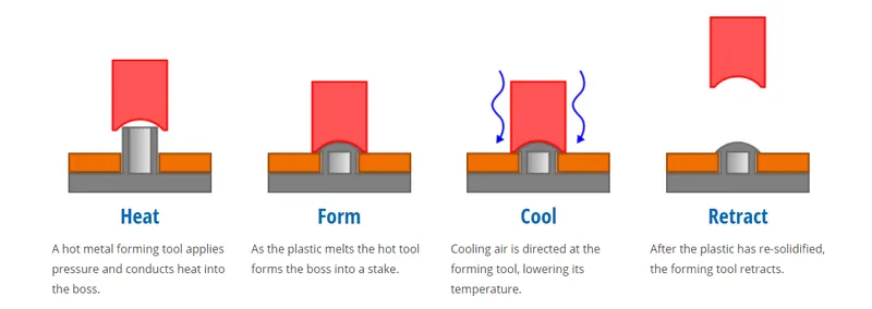
figure 1: - Thermal staking or Heat staking process
The progressive melting of plastic under continuous pressure forms the head. When staking, the right combination of heat and pressure for the application is critical. Advantages of heat staking are the simplification of machinery, reduced cost of machinery, multiple fastening points, and allowing a higher density of welds compared to hot air cold form or ultrasonic welding.
The same guidelines which are used for making screw bosses are used to make these stakes. For example, minimum draft of 0.5 degrees, optimum fillet of 0.25 mm, etc. The minimum gap between the stakes should be 50 mm.
2. Locators: -
In the automotive tooling industry, you will hardly get any designer who does not know the 3-2-1 principle. If any part, for example, a steel block is to be machined using a milling machine, the first question the milling machine operator will think is how I will hold the part. The operator will use the various clamps to hold the job to withstand the cutting force. Ideally, a 3-2-1 principal is used to locate the job. Any part which has to be fixed during welding or during the machining process has 12 degrees of freedom as shown in the below figure 2. They are - Translational movement along the x-axis, Translation movement along the y-axis, Translation movement along the z-axis, Rotational movement along the x-axis, Rotational movement along the y-axis, and Rotational movement along the z-axis.
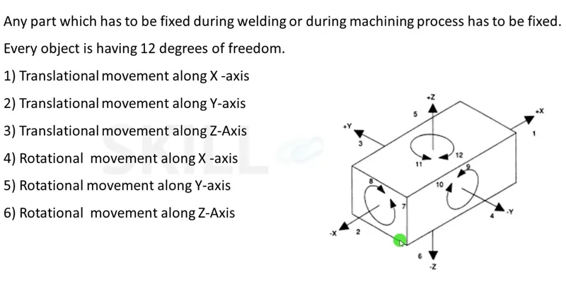
figure 2: - 12 degrees of freedom
In this case, locators are used for restricting the movement of the welding surface and door applique. The same guidelines which are used for making ribs are used to make these locators. For example, a minimum draft of 0.5 degrees, optimum fillet of 0.25 mm, etc.
3. Tooling axis creation for Door Applique model (with Locators and Heat stakes): -
The tooling axis indicates the direction along which the tooling or the manufacturing of the component will be done. In CATIA, the tooling axis is used to create C surfaces using the sweep option. There are many methods for the creation of the tooling axis and bisecting method is one of them.
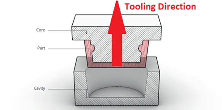
figure 3: - Example of tooling axis direction
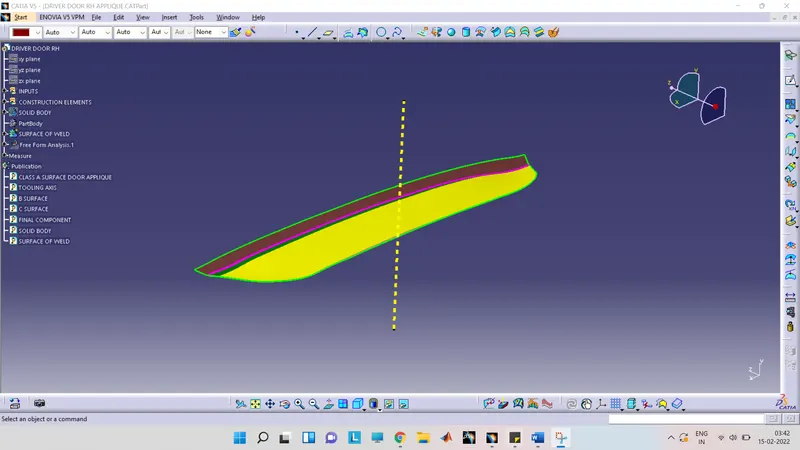

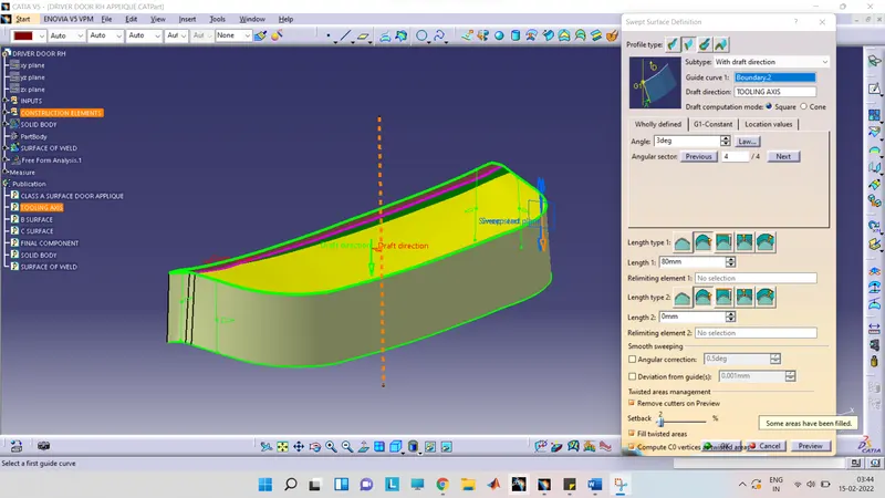
figure 4: - Use of tooling axis in CATIA (C surface)
The steps involved in creating tooling axis using the bisecting method are as follow: -
- Check continuity or quality of Class A surface
- Selection of best possible tooling direction
- Creating dummy tooling axis
- Tooling clearance for respective directions
- Creating final tooling axis
step1: - Check continuity or quality of Class A surface
Product designers should check the continuity or quality of the class A surface given by the class A engineer. They should ensure that there are no gaps between the surfaces using the boundary or the join command in CATIA.
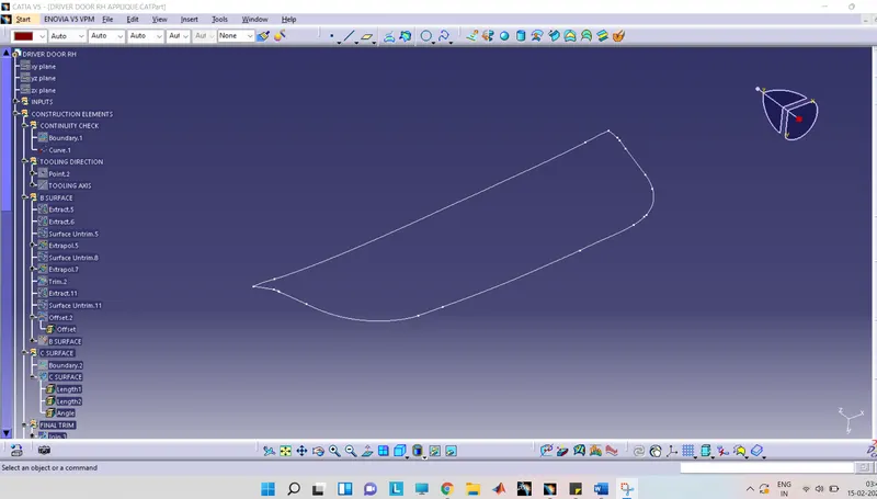
figure 5: - Checking the continuity (using boundary command)
step2: - Selection of best possible tooling direction
The tooling direction should be in such a way that it should cover the complete component along with its holes, undercuts, etc. in the main tooling. The product designer should also avoid side cores because the side cores generally increase the manufacturing cost of the component.
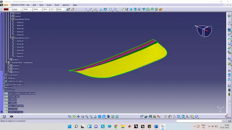
figure 6: - Door Applique Model
Since, there are no sidewalls present in the component, by default y direction will be the best tooling direction for the Door applique as shown in figure 7.
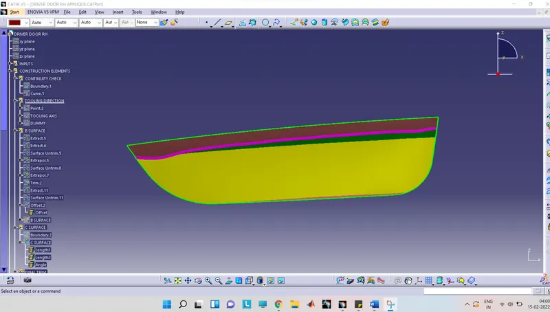
figure 7: - y-direction
step3: - Creating dummy tooling axis
The dummy tooling axis is a line or an axis created at the center along the y-direction as shown in figure 7. The dummy tooling axis is used just as a reference and it is not the real tooling axis as shown in figure 8.
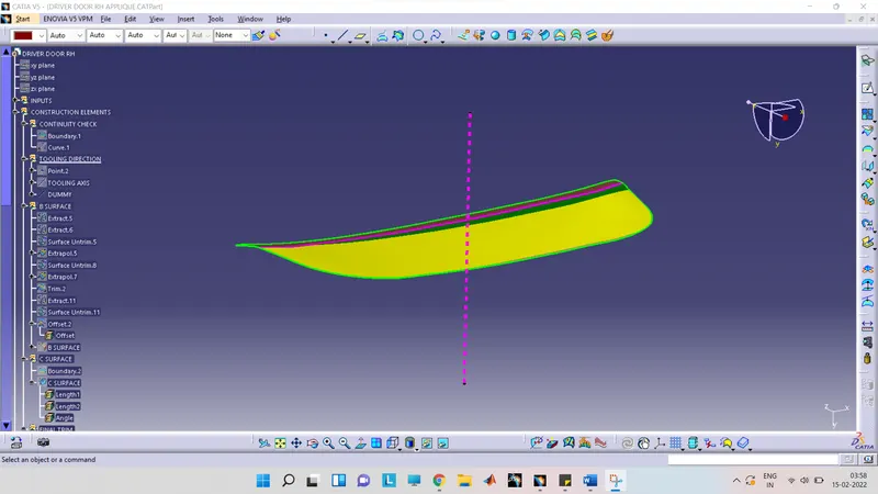
figure 8: - Dummy tooling axis
step4: - Tooling clearance for respective directions
This step is skipped because we directly chose y-direction as our tooling direction as shown in figure 7 and made the tooling axis directly for the y-direction taking the center of the component as shown in figure 9. Basically, there is no involvement of bisecting method in this case.
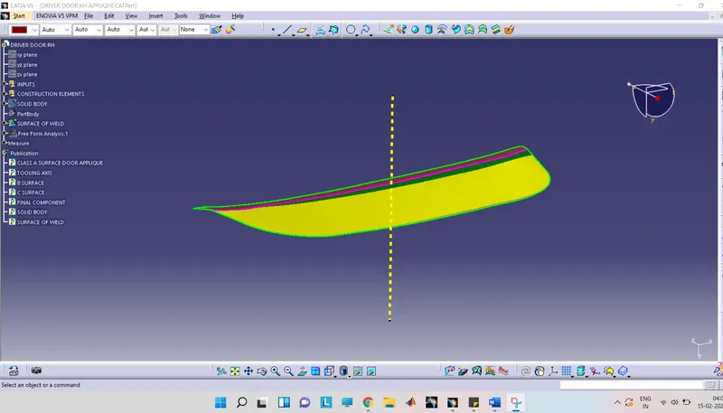
figure 9: - Main tooling axis
4. Publication: -
Using the publication option, the important parts of a model are easy to search as shown in figure 10.
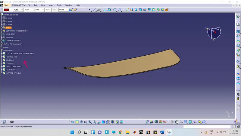
figure 10: - Door Applique Model, Class A, B, and C and tooling axis are easy to search
5. Draft Analysis on Door Applique Model (with Locators and Heat stakes): -
Draft: - Draft is providing angles or tapers on product features such as walls, ribs, posts, and bosses that lie parallel to the direction of release from the mold that eases the part ejection.
The draft is required on all parts in the direction of mold movement in order to allow parts to release or eject from the mold properly. The draft is the angle at which the part is tapered to allow it to release. As the part cools, it tends to shrink to the core side of the mold. Adding draft helps the part to release. 3 degrees is the nominal draft. Whereas, 0.5 degrees can also be manufactured at ribs. 7 degrees for the textured faces.
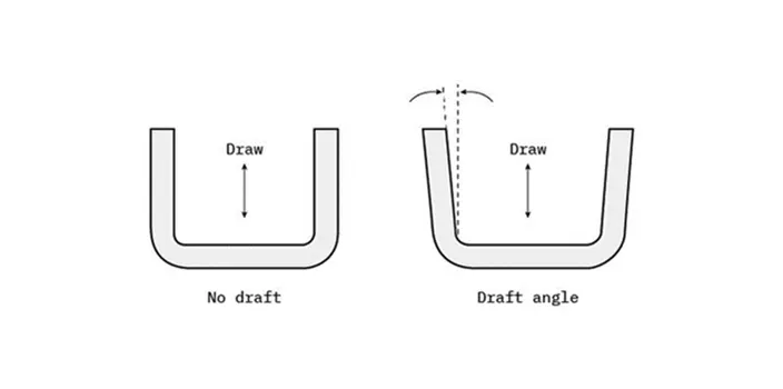
figure 11: - Example of draft
Draft analysis is used to confirm the appropriate draft angle required for the component that is to be manufactured. Quick analysis mode, show or hide color scale, and analysis under the running point are the three main features used in the draft analysis. The color scale shows the draft angle for different colored areas as shown in figure 12 and the analysis under the running point shows the draft angle at different points as shown in figure 13.
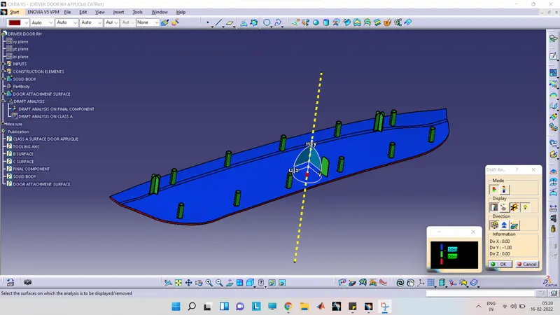
figure 12: - show or hide the color scale
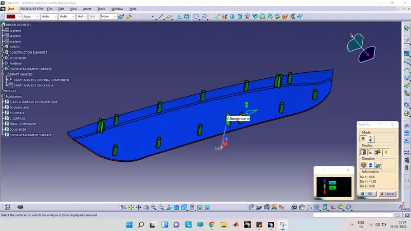
figure 13: - Analysis under the running point
Screenshots of the Draft analysis report: -
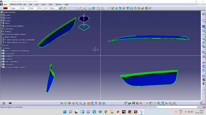
- Screenshots of the Draft analysis report for Class-A surface: -
- Image of the complete Draft analysis: -
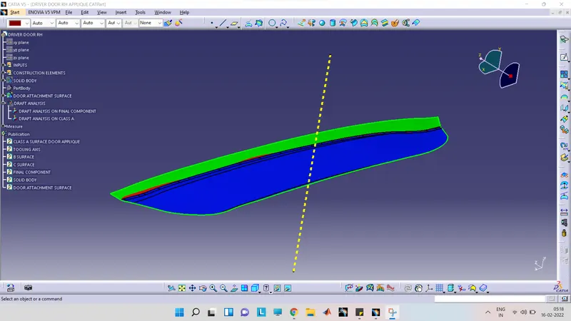
- Images of the color scale variant: -
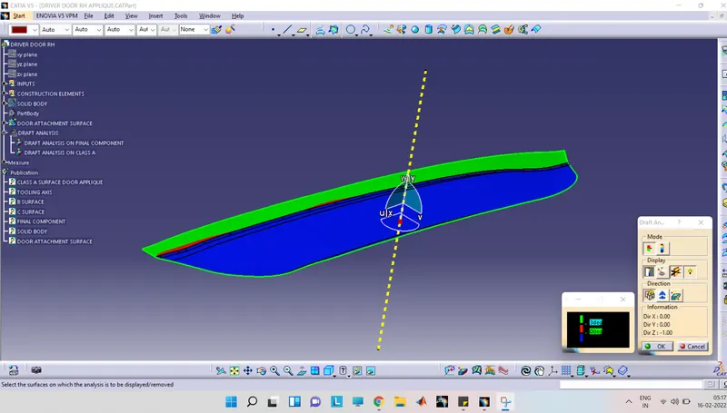
- A model with the proper color code of the draft angle in various orientations (Isometric, Front, Side, and Top View): -
- Screenshots of the Draft analysis report for the final plastic component(with Locators and Heat stakes): -
- Image of the complete Draft analysis: -
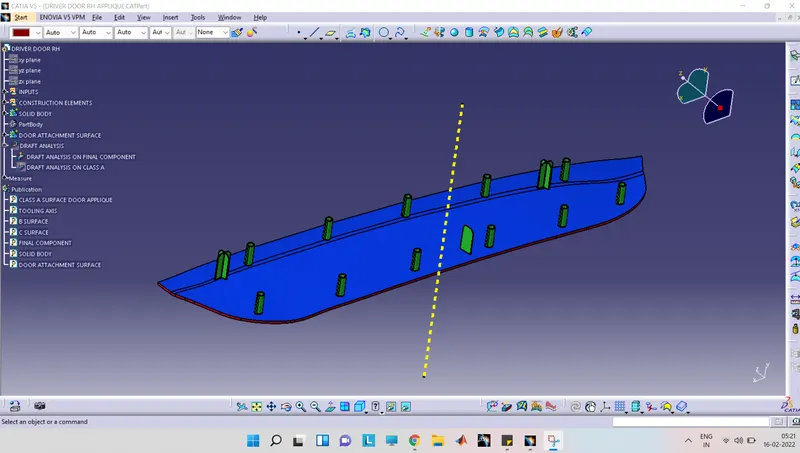
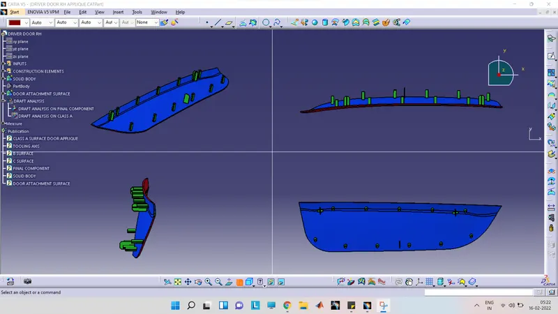
- Images of the color scale variant: -
- A model with the proper color code of the draft angle in various orientations (Isometric, Front, Side, and Top View): -
Other images: -
- Final component with Locators and Heat stakes
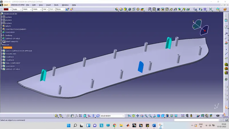
- Screenshots of the completed design in various orientations (Isometric, Front, Side, and Top View)
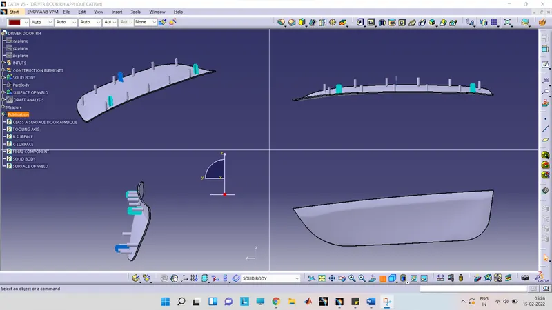
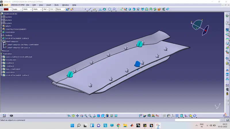
- Final component with Locators, Heat stakes, and Door attachment surface
Conclusion: -
- Troubleshooting different problems while operating on software is one of the skill-enhancing techniques.
- Paste special is one of the interesting commands in Catia for making n number of copies of the same feature without actually building them again.
- While operating on software, if one gets a feature involved in an update cycle error then one out of the two sketches or features which are interrelated to each other should be isolated to solve that error temporarily.
- The dimensions of heat stakes generally depend upon the manufacturer and tool.
- The thermal staking process is an economical, repeatable, and safe method for thermoplastic assemblies.
- Heat staking can be performed using a wide range of thermoplastic materials including polypropylene, ABS, polycarbonate, and many others.