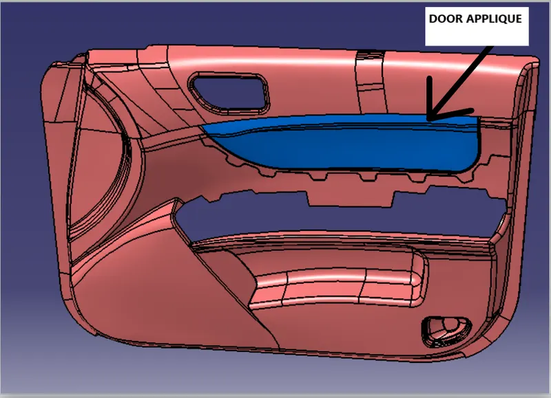
Week 9 - Project 1 - Door Applique Design with Engineering Features
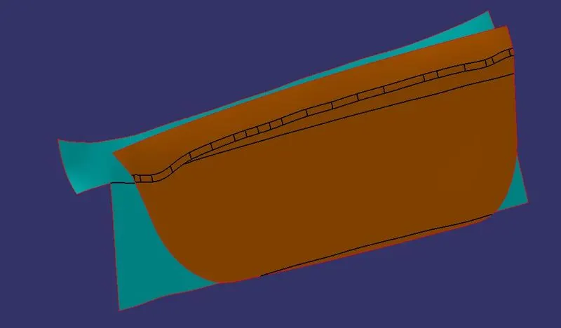
AIM: Creating Locators and Heat Stakes for the Door Applique.
THEORY :
Locators: Locators are the attachment in the plastic component which guides the component to get fitted into other surfaces going through clearance holes, there are mainly four and two-way locators. 4-way mean you prevent movement at 2 axes (+X, -X, +Y, and -Y) on the plane. 2-way means you prevent movement only at 1 axis on the plane.
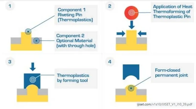
Heat Staking Process: Heat staking also known as thermoplastic staking is the process of joining two dissimilar materials together. The plastic is plasticized with the electrically heated riveting punch at the point of contact. It is then formed and pressed together under pressure. Once the power is off, cool air is used to cool the plastic.
Location Principle :
- The 3-2-1 or 6 Point Location principle is used to constrain the movement of the workpiece (to be machined/fixed) along the 3 axes XX, YY, and ZZ.
- It is achieved by providing 6 pin locations: 3 on the Base plane, 2 on the Vertical plane, 1 on the plane perpendicular to the first two planes.
APPROACH TO WORK ON PROJECT :
- Creating Tooling Axis.
- Creating Class B Surface.
- Creating Class C Surface.
- Creating Locators.
- Creating Heat Stakes.
- Creating Clearance Hole for Heat Stakes.
- Creating Clearance Hole for Locators.
- Performing Feature Draft Analysis.
PROCEDURE FOR CREATING TOOLING AXIS :
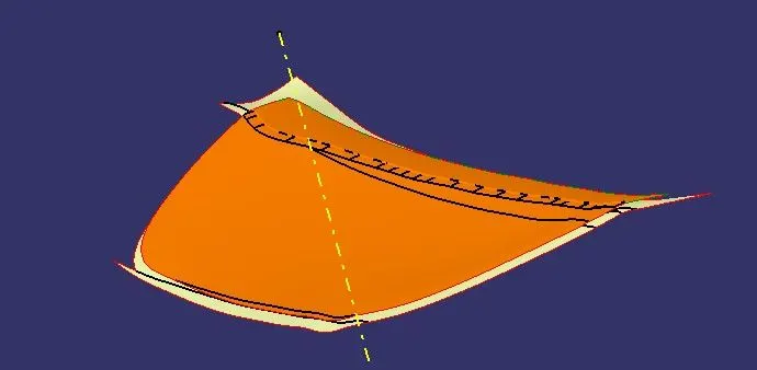
Tooling Axis: The tooling axis is the direction in which mold or core and cavity are opened. Check all possible tooling directions in all three axes. When we are deciding the tooling axis we have to make sure that all the faces should be visible to that tooling axis, no face should be hidden.
STEP 1: Ensure there is no gap between the two neighboring surfaces.
Operations>Boundary>definition>select component
STEP 2: Create a point in the middle of the Class A surface of the door panel using the surface point definition panel.
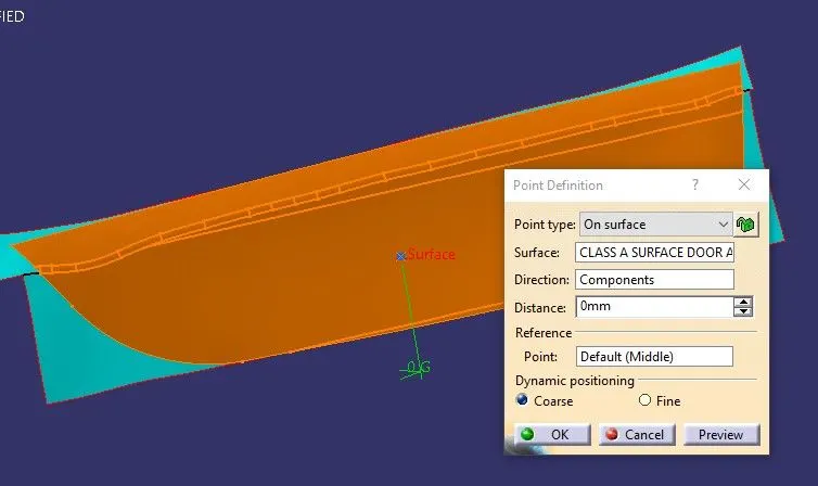
STEP 3: Create a Plane parallel to the XZ plane on the created point.
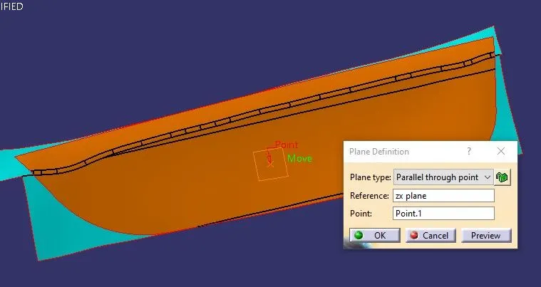
STEP 4: Extracting Tooling Axis.
For this component, the Y-axis will be the best tooling axis as we can see all the faces of the component.
Extract a line from that point towards the Y direction.
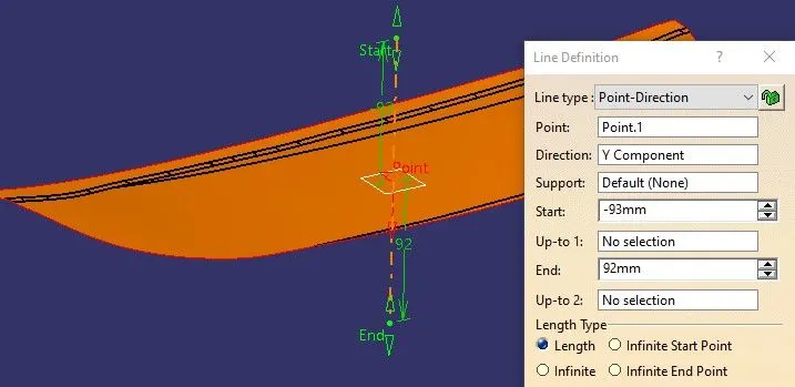
STEP 5: Rename, change color and give thickness to the tooling axis so that it can be easily identified.
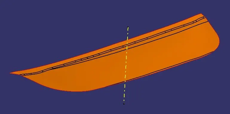
STEP 6: Publish Tooling Axis.
Select tooling axis in model tree>Toolbar>tools>publication>ok
PROCEDURE FOR CREATING B SURFACE :
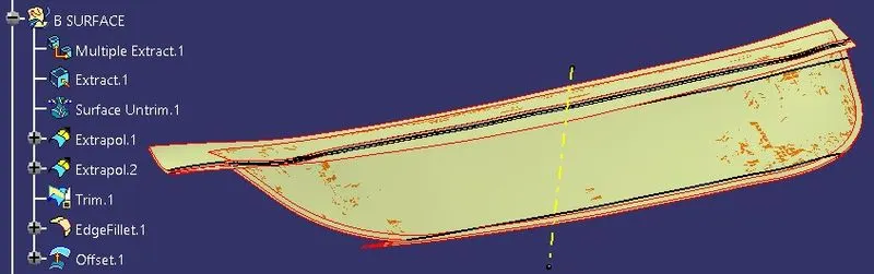
STEP 1: Multiple extracts the one surface of the A class of side door.
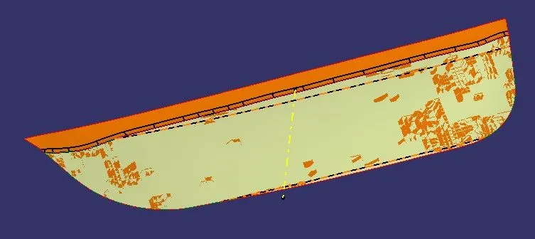
STEP 2: Extract another surface above the fillet of the A class of side door.
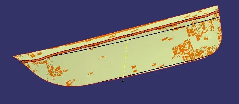
STEP 3: Untrim and Extrapolate both the extracted surfaces.
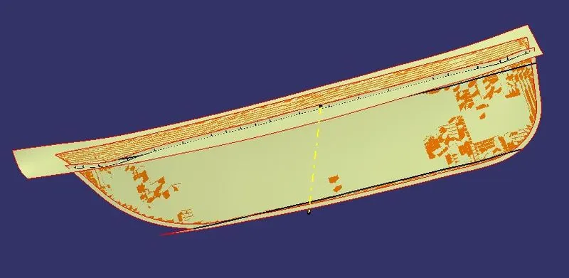
STEP 4: Trim both surfaces
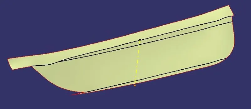
STEP 5: Give an edge fillet of 15(dia)+2.5(thickness) = 17.5mm of fillet to the trimmed surface.
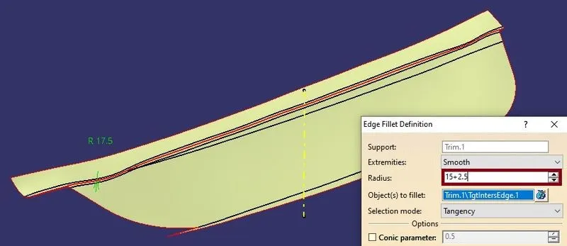
STEP 6: Offset the surface to 2.5mm below.
- Model Tree for B surface creation.
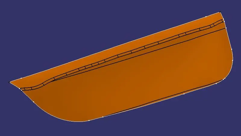
PROCEDURE FOR CREATING C SURFACE :
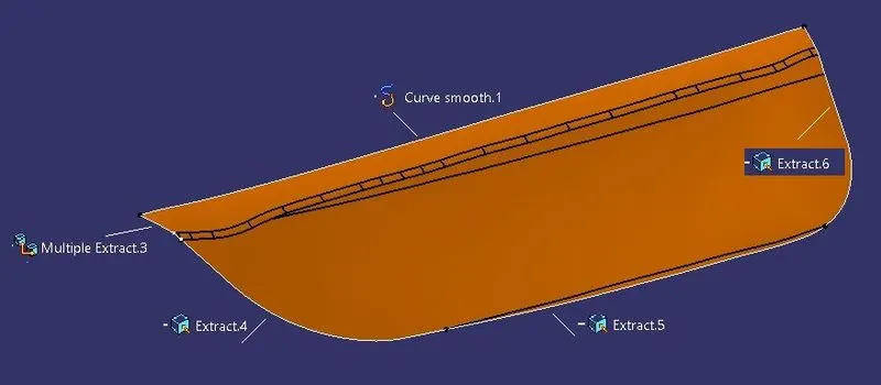
STEP 1: Extract the boundary from the Class A surface of the side door.
STEP 2:
- Give the smooth curve option but freeze two points as mentioned below.
- Now extract each line after points.
- These different lines will help us to sweep the surface towards the outward direction from the component, otherwise if we take only a single boundary line, sweep we will be extracted toward one direction only due to which draft analysis will fail.
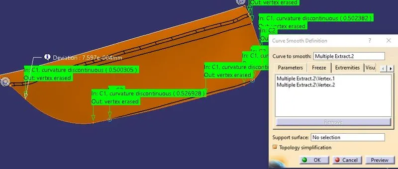
- We can see all the extracted lines separately.
STEP 3: Sweep all the lines using sweep with direction panel
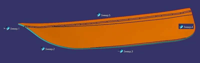

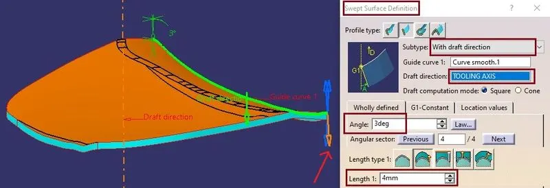
NOTE: Sweep the curve with the following parameters.
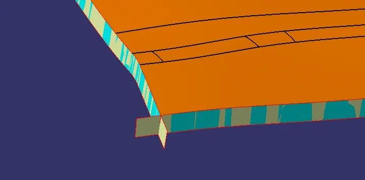
STEP 4: Extrapolate the sweeps and trim them to get popper closed surfaces of sweeps.
STEP 5: Join All the sweeps with Class A surfaces of the side door.
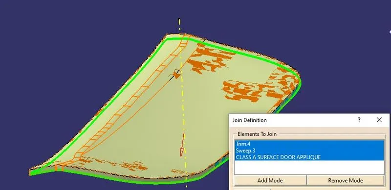
- We can see C Surface as below -
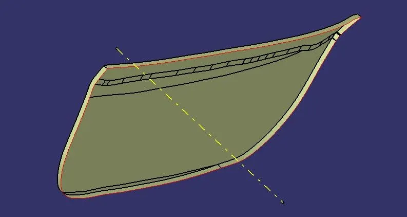
STEP 6: Unhide Offsetted surface of the side door panel and join the C surface.
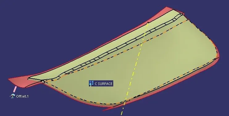
STEP 7: Trim both surfaces
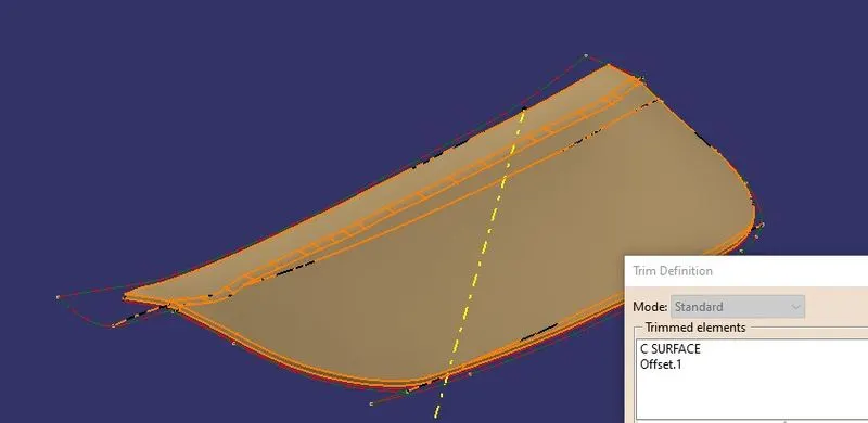
- We can see the thicken surface after trimming as below -
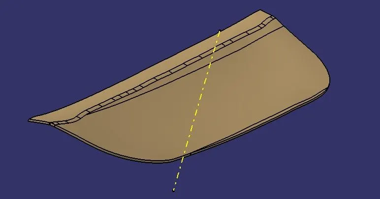
STEP 8: Switch to Part Design Workbench, Define Part body to make it a solid component by the surface panel.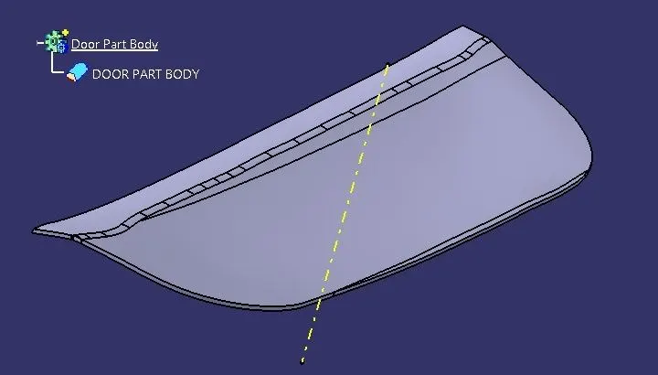
STEP 9: Thicken the A class Door Attachment Surface of the side door.
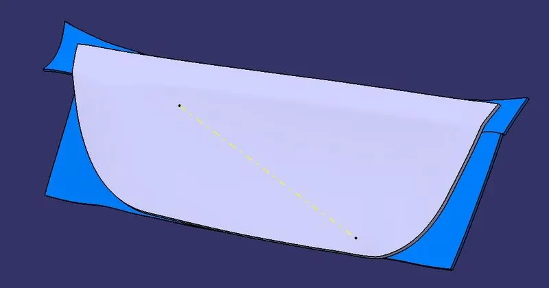
PROCEDURE FOR CREATING LOCATORS :
STEP 1: Create a point on the door attachment surface using on surface point definition panel.
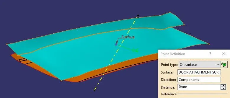
STEP 2: Create a plane parallel XZ plane on the point.
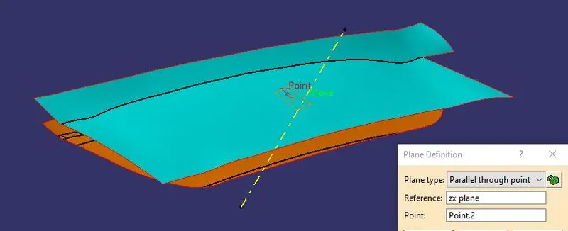
STEP 3: Sketch for 4 way Locator.
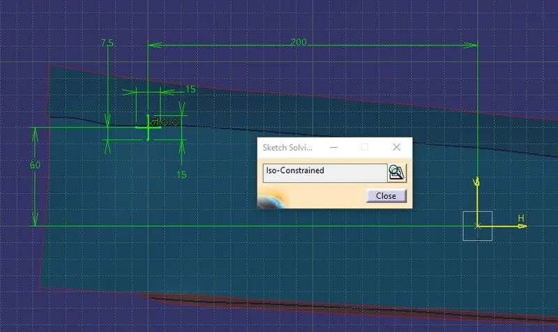
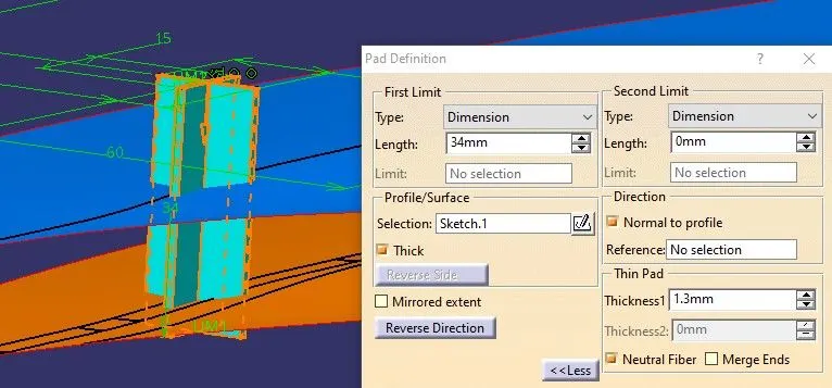
STEP 4: Pad the sketch with 1.3 mm thickness and the following parameters.
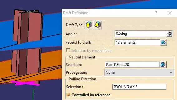
STEP 5: Draft all the faces of the 4-way locator with 0.5 degrees and other parameters shown below.
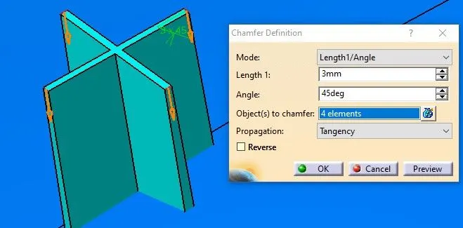
STEP 6: Give a Chamfer of 3mm with 45 degrees.
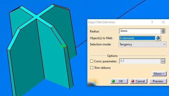
STEP 7: Give an edge fillet of 3mm on the chamfer area.
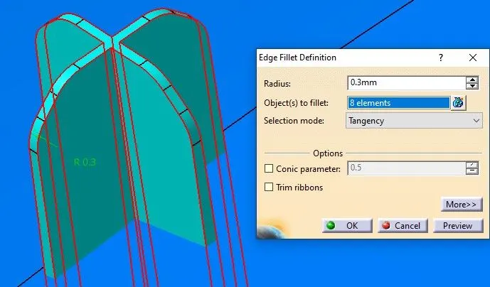
STEP 8: Give an edge fillet of 0.3mm on all the faces of 4-way locator.
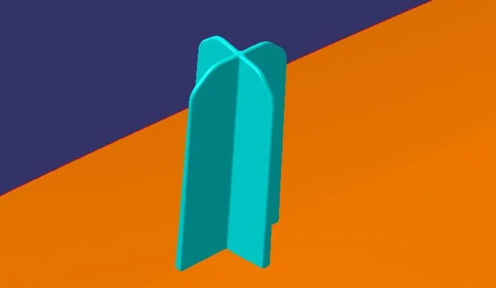
- We can see 4 way locator after all operations as below -
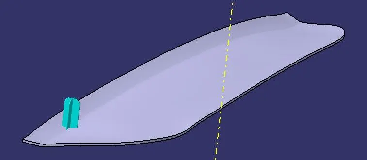
STEP 9: Translating the Copy of 4-way locator to another position.
- Copy the Body of the 4-way locator.
- Special paste it on the main tree.
- Translate the body with translate with coordinate definition panel.
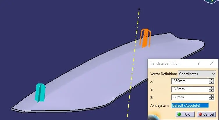
- We can see the translated 4-way locator as below -
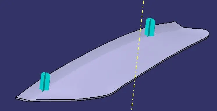
STEP 10: Sketch for 2 Way Locator
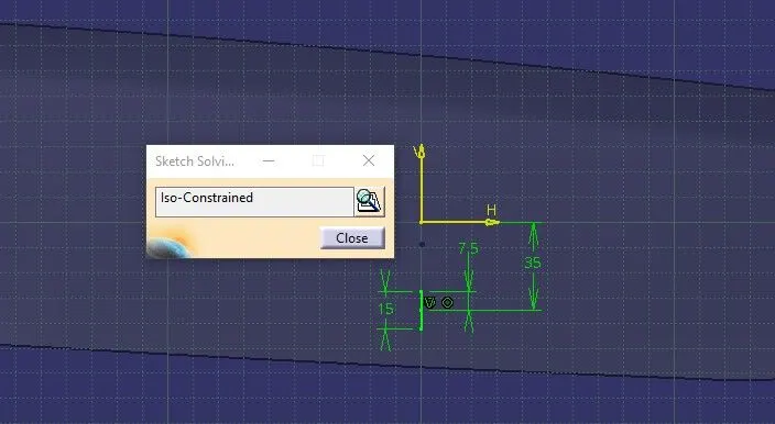
STEP 11: Follow the same steps which we did for the 4-way locator also.
- Pad, Draft, Chamfer, Edges Fillets.
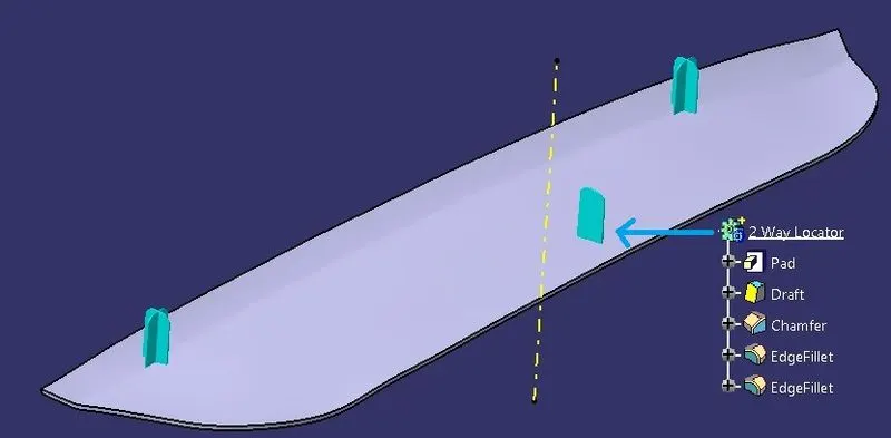
PROCEDURE FOR CREATING HEAT STAKES :
STEP 1: Extract the parallel lines of 15mm from the boundaries of the car's applique edges.
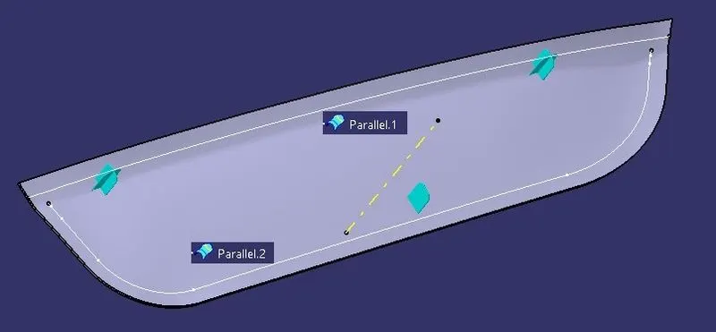
STEP 2: Create the few points where we want to make heat stakes from the point and plane repetition panel.
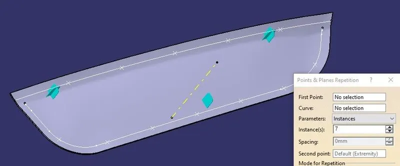
STEP 3: Sketch for Heat Stake.
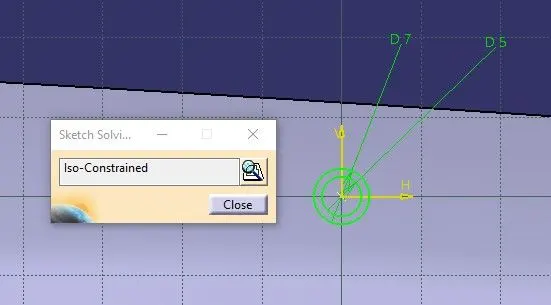
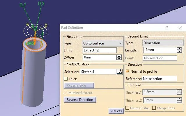
STEP 4: Pad the sketch of the heat stake and give a draft of 0.5 degrees as shown below.
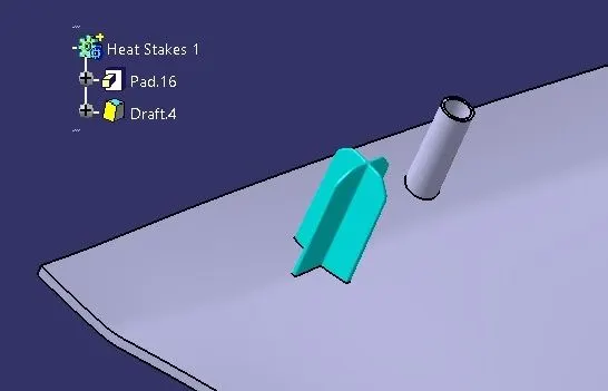
STEP 5: Translating the Copy of the first heat stakes to other positions.
- Copy the Body of the 4 heat stakes.
- Special paste it on the main tree.
- Translate the body with a point to point translate definition.
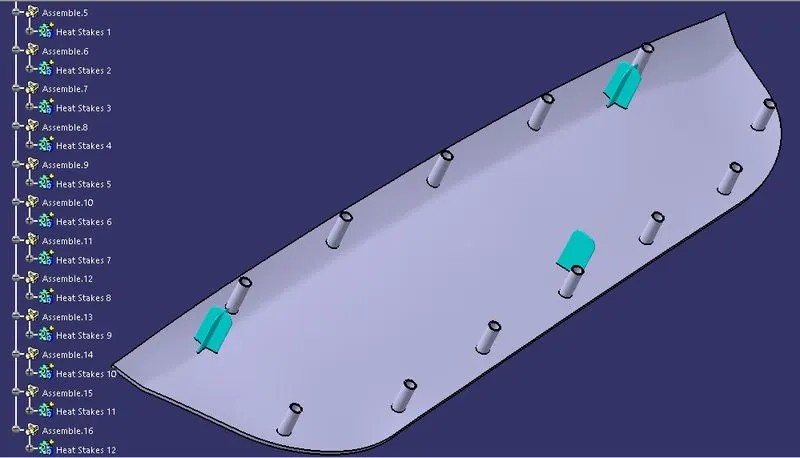
- Follow this for all remaining positions of heat stakes
- Assemble all the heat stakes bodies to one Body.
STEP 6: Boolean operation, Add that assembled body to the main part body of the door applique.
PROCEDURE FOR CREATING CLEARANCE HOLE FROM HEAT STAKES :
STEP 1: Sketch for clearance hole to be made on attachment surface.
- Copy and paste the same sketch of the heat stake.
- Remove the inner diameter of the heat stake.
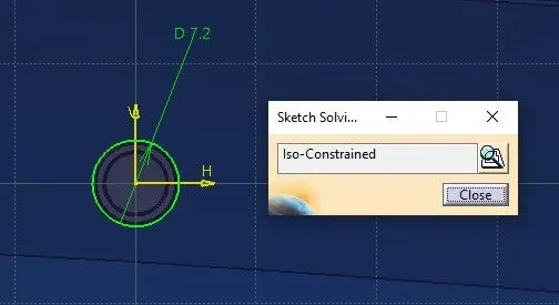
- Increase outer dia (clearance circle) to 7.2 mm
- NOTE: The outer dia of heat stakes was 7mm, so we are providing 0.1 mm clearance to both sides on the clearance hole sketch, so dia will be 7.2mm.
STEP 2: Pad the clearance hole for heat stakes towards the attachment surface of the door applique.
- NOTE: We are providing a second limit length to -8mm to avoid more clearance distance between heat stakes and holes on the attachment surface.
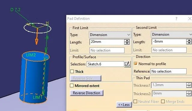
STEP 3: Draft the Clearance hole pad to 0.5 degrees and other parameters shown below.
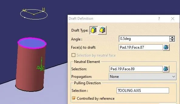
STEP 4: Translating the Copy of the clearance hole body to the same position of all heat stakes.
- Copy the Body of the clearance hole body.
- Special paste it on the main tree.
- Translate the body with a point to point translate definition.
- Follow this for all remaining positions where heat stakes are placed.
- Assemble all the clearance hole bodies into one Body.
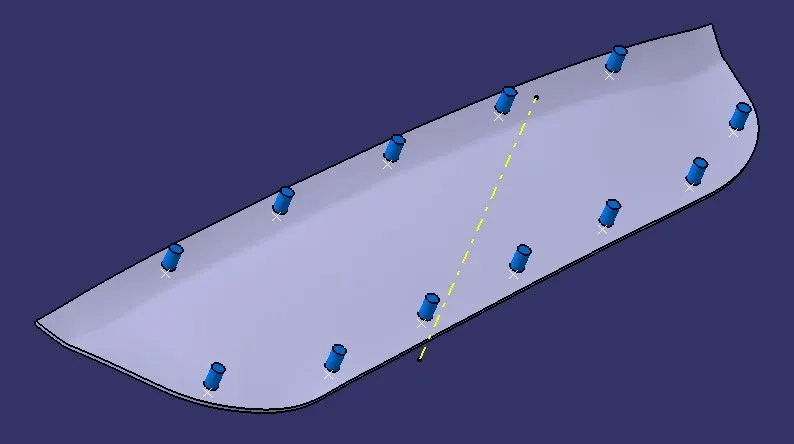
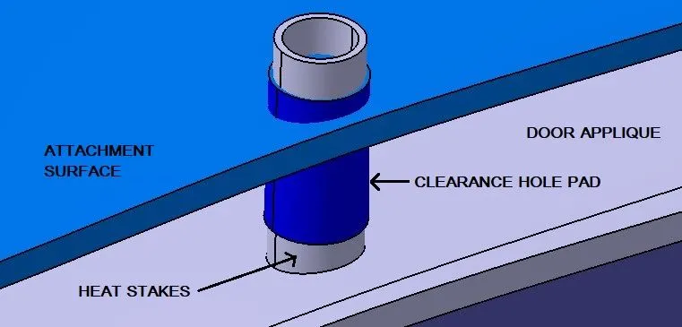
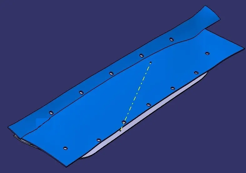
STEP 5: Boolean operation, Remove the Assembled body from the Attachment surface of the door applique, the attachment surface can be seen as below.
PROCEDURE FOR CREATING CLEARANCE HOLE FROM LOCATORS :
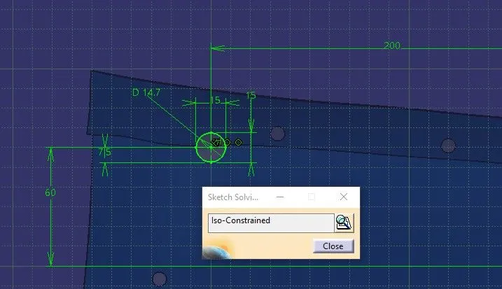
STEP 1: Sketch for clearance hole to be made on attachment surface for locators.
- Copy and paste the same sketch of the first 4-way locator.
- Make all the lines as construction lines.
- Add a circle 14.7 mm Diameter.
- NOTE: The length of both lines of the 4-way locator was 15mm.
- NOTE: The diameter of this circle is 14.7mm, so we are reducing 0.15 mm clearance to both sides on the sketch, so dia will be 15mm-0.15mm-0.15mm = 14.7mm.
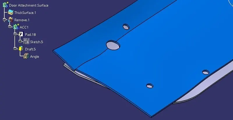
STEP 2: Boolean operation, Remove the clearance body of the 4-way locator after giving pad and draft to above sketch as shown below-
- We can see the all heat stakes holes and 4-way locator clearance hole as below.
STEP 3: Sketch for second clearance hole for the second 4 way locator
- Use Project 3D element to extract four lines from the 4-way locator as shown below (Four Yellow Lines).
- Use Bisect lines on each pair of extracted 3D element lines.
- Place a point where both bisecting lines are intersecting.
- We got a center Point.
- Make all the lines as construction lines.
- Add a circle 14.8 mm Diameter from that point.
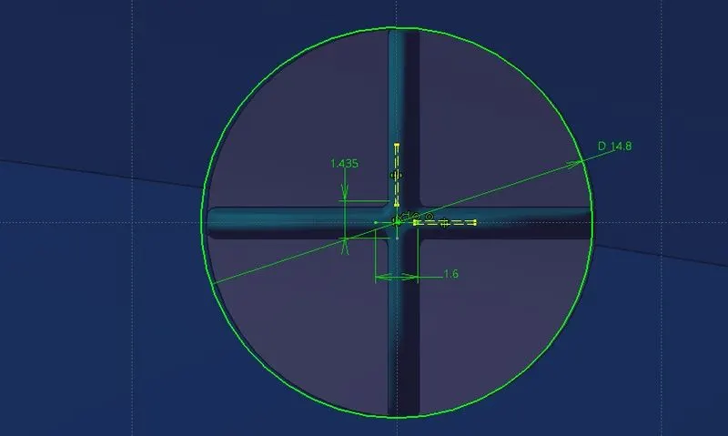
STEP 4: Boolean operation, Remove the clearance body of the second 4-way locator after giving pad and draft to above sketch as shown below-
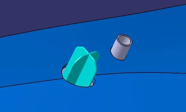
STEP 5: Sketch for clearance hole for the 2-way locator.
- Copy and paste the same sketch of the 2-way locator.
- Make all the lines as construction lines.
- Add a circle 14.7 mm Diameter.
- NOTE: The length of the line of the 2-way locator was 15mm.
- NOTE: The diameter of this circle is 14.7mm, so we are reducing 0.15 mm clearance to both sides on the sketch, so dia will be 15mm-0.15mm-0.15mm = 14.7mm.
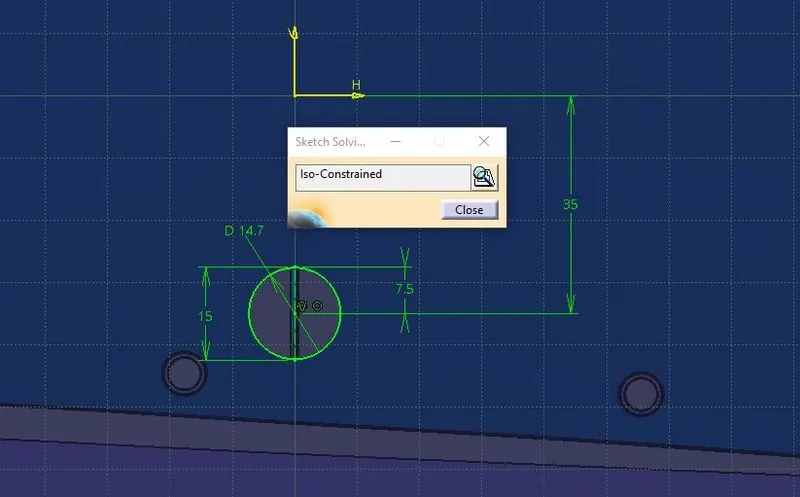
STEP 6: Boolean operation, Remove the clearance body of the second 4-way locator after giving pad and draft to above sketch as shown below-
- Keep checking the distance of all the locator and edge of their respective clearance holes, it should be as minimum as possible.
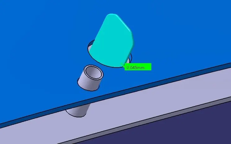
RESULTS :
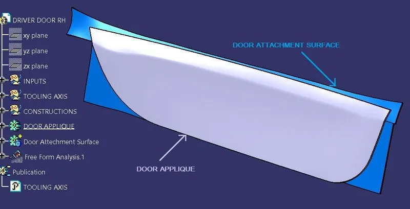
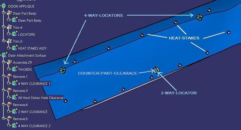
PROCEDURE TO CHECK DRAFT ANALYSIS :
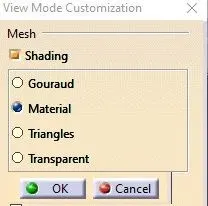
STEP 1: Changing view mode to the material.
View mode>view mode customisation>tick material>ok
STEP 2: Calling Draft Analysis.
Toolbar>Insert>Analysis>Feature Draft Analysis
STEP 3:
- Drag the compass from the draft analysis box on the tooling axis and place it properly.
- Click on locks so the compass will get locked to the tooling axis.
- Click anywhere on the component.
- Click OK.
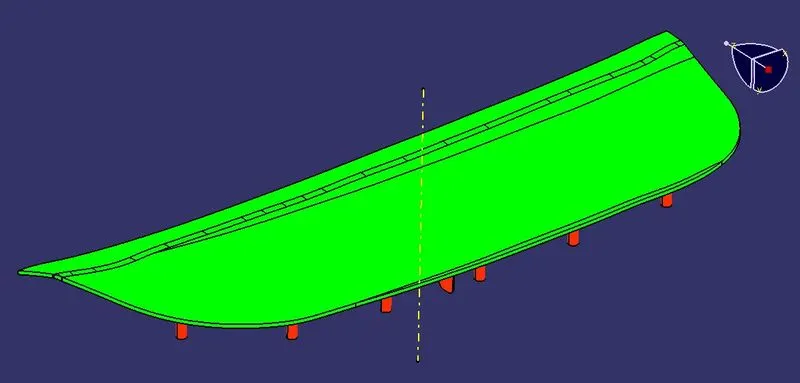
- Analysis of the color of the failing and passing surfaces.
If a component is showing in a Green color that means our component is ready for manufacture.
NOTE: If we find zero degree or negative degree failing color, we can fix it by changing the draft angle, sweep direction, modifying properly tooling axis, etc.
- Feature Draft Analysis on class A Door Applique.
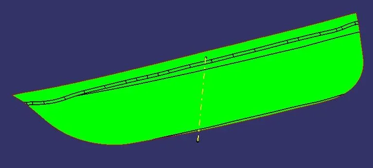
- Feature Draft Analysis on Above side of surfaces of Door Applique Part Body.
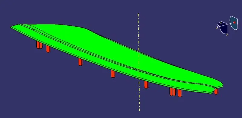
- Feature Draft Analysis on Below side of surfaces of Door Applique Part Body.
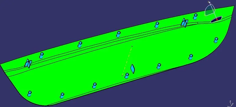
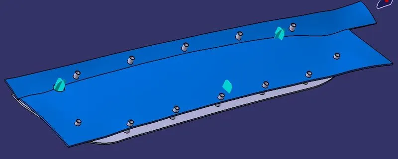
We can see blue color on 2 and 4-way locators and heat stakes because we have provided 0.5 degrees of the inside draft with respect to the tooling axis.
CONCLUSION :
Creation of the Locators and Heat Stakes has been successfully done by guidance of design rules, also part clearance holes made on the attachment surface of applique. The tooling axis has been created according to the OEM standard.
LEARNINGS :
- Creating tooling axis.
- Creating class B surfaces.
- Creating class C surfaces.
- Creating 4 way and 2-way Locators.
- Creating Heat steaks.
- Application of locators and heat stakes.
- Creating Counter Part Clearance Holes.
- Translating solid parts by coordinates and point-to-point definition.
- Feature Draft Analysis on Door Applique, Locators, and Heat Stakes.