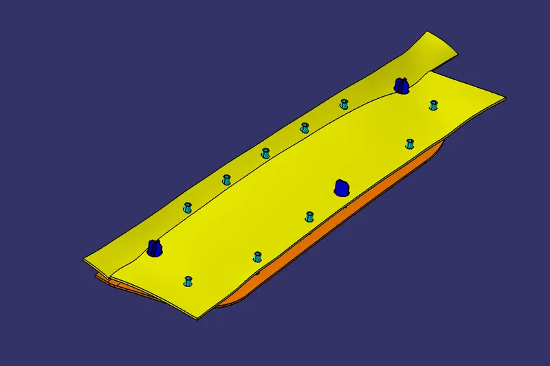
Door Applique Design with Engineering Features
DOOR APPLIQUE DESIGN WITH ENGINEERING FEATURES
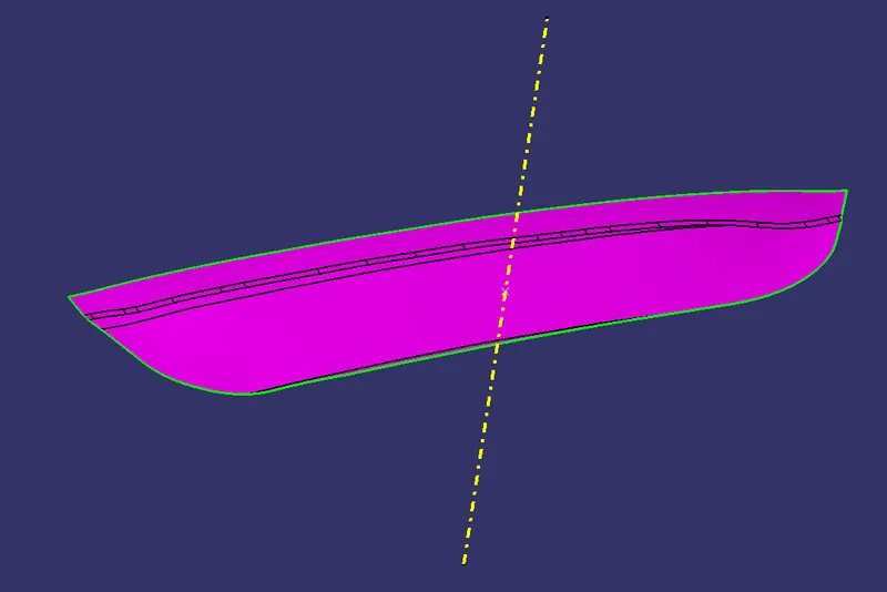
CREATING TOOLING AXIS:
- For obtaining the tooling direction, we will consider all the 3 axes and view the part along them.
- After viewing the part in different views, we can conclude that direction along Y axis is appropriate for our tooling axis.
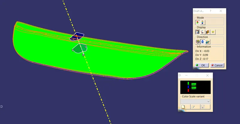
- Take a point on the center of class A surface and then take a line normal to the surface and through that point. By taking draft analysis for the same line, we can confirm that it is appropriate tooling direction. Results for draft analysis are shown in the image section later.
DESIGN METHODOLOGY:
Class B & C surfaces:
- After obtaining the tooling axis, develop the class B and class C surfaces with proper design regulations to get the enclosed surface body.
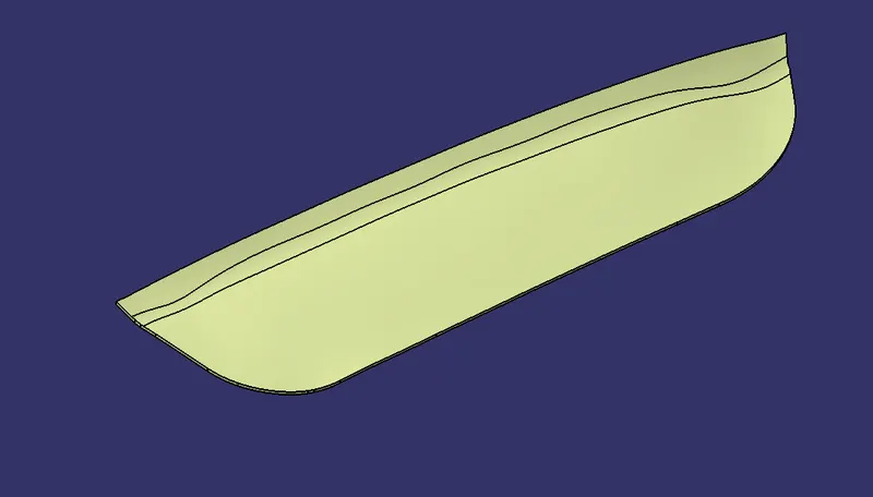
- Then get the solid body by using ‘Thick surface’ command.
Locators:
- After that we need to create locators.
- For the 4-way locator we take a plane normal to tooling axis and through the previous point.
- Then take a sketch as shown below.
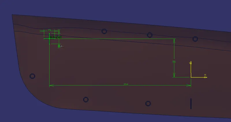
- After that, extrude the sketch for proper length using Pad command and thicken it by 1.25 mm. Make sure the pad is along tooling axis direction.
- Then apply draft to vertical walls with a draft angle of 0.5 degrees along the tooling axis. After that you can apply chamfers to top edges and fillets to all edges.
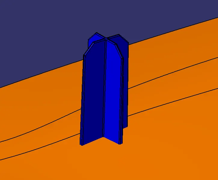
- Now copy and paste the same body with ‘Paste special’ option and ‘As result with link’ under that.
- Then add both the parts to applique body using ‘Union Trim’ boolean operation.
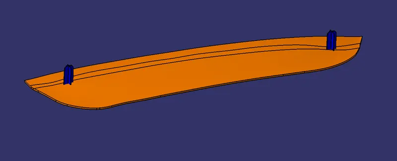
- Further, for 2-way locator take a sketch on the previous plane and draw as shown below.
- Then extrude for appropriate length using Pad command and thicken by 1.25 mm.
- Add drafts to vertical walls with draft angle of 0.5 degrees and then add chamfers and fillets accordingly.
- Then add the body to main applique body using ‘Assemble’ boolean operation.
Heat Stakes:
- Extract the edges of class B surface and offset them towards the surface center using ‘Parallel curve’ feature.
- Then, using ‘Point repetition’ option, take points with required numbers and at appropriate instances. Then take a sketch on the previous plane and centered at the 1st Draw as shown below.
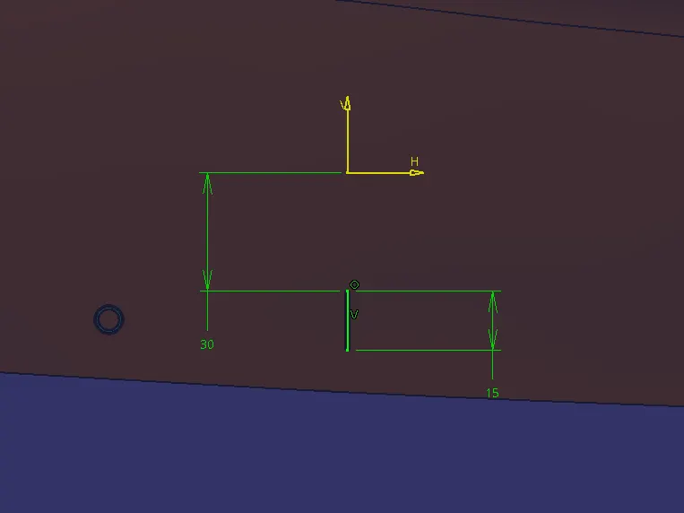
- Extrude the sketch using ‘Pad command’ and apply draft of 0.5 degrees to inside and outside.
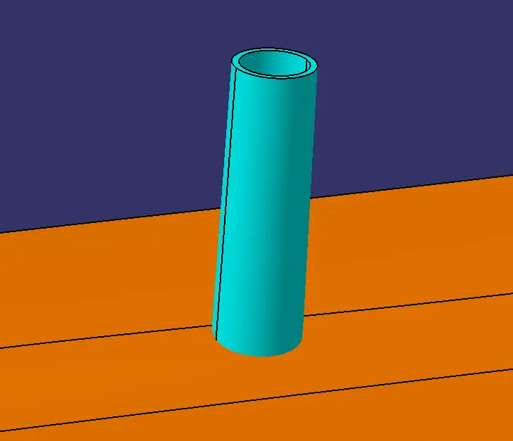
- Now, similar to the 4-way locator, copy, paste and translate the heat stake to each point using point to point translation.
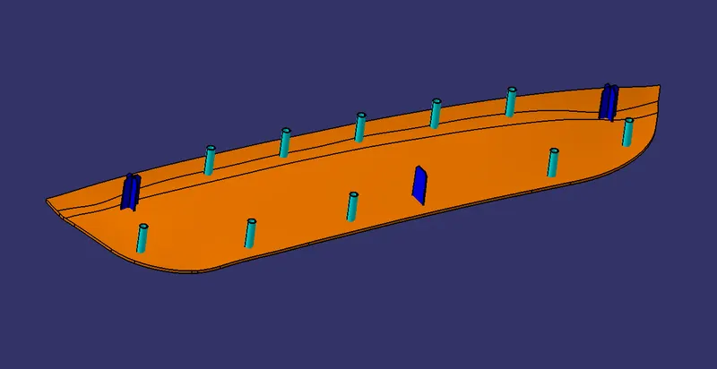
- Add all the heat stakes to one single body using ‘Assemble’ boolean operation.
- Now add fillets to the base edges with appropriate values.
IMAGES
DRAFT ANALYSIS AND COLOR SCALE VARIANT
Class A Surface
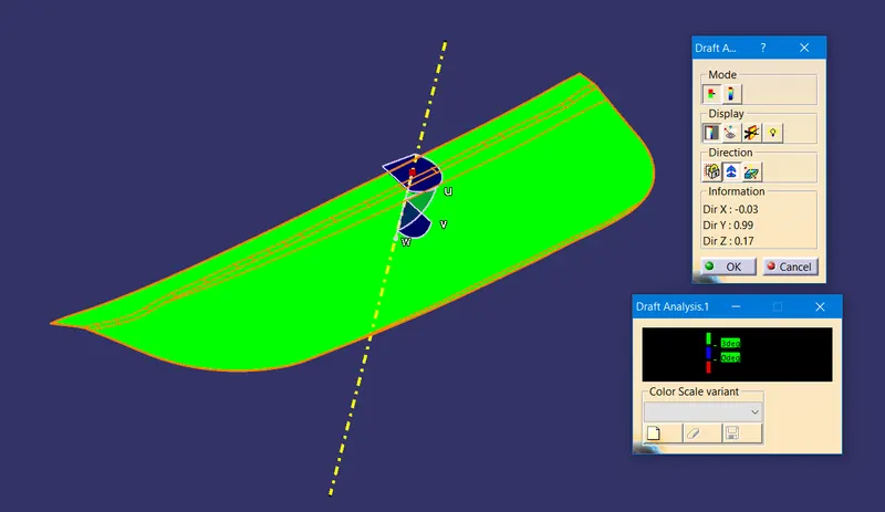
Door Applique Surface Body (Without locators and heat stakes)
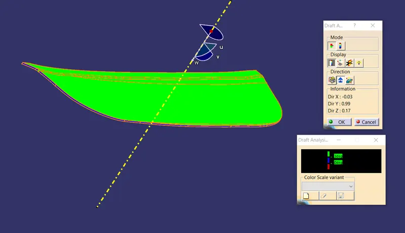
Door Applique Solid Body (Without locators and heat stakes)
Door Applique Final Body
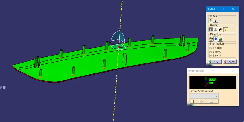
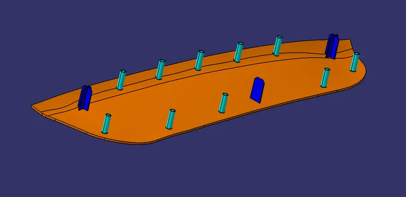
As you can see above, the locators and heat stakes are found to have positive drafts at 0.45 degrees.
Door Attachment Solid Body
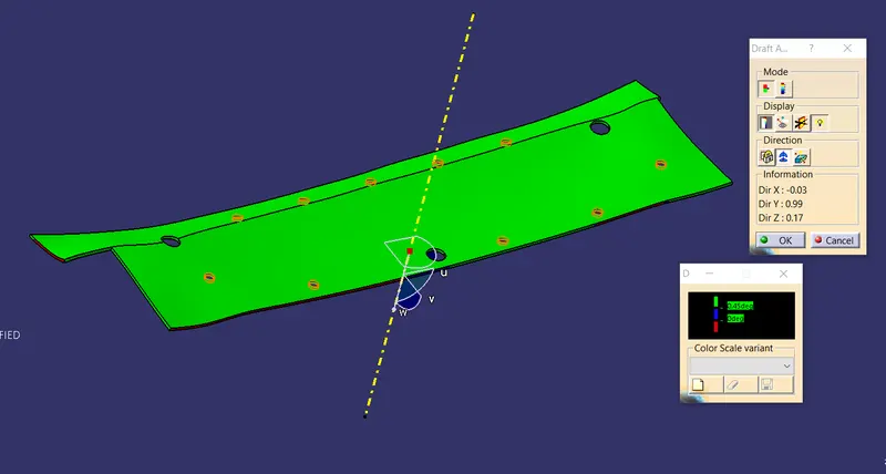
It can be seen above that the door attachment slots have positive draft for clearance holes at 0.45 degrees.
MODEL DIFFERENT VIEWS
Door Applique Surface Body (Without locators and heat stakes)
Front view
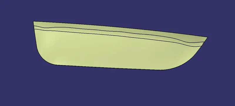
Side view
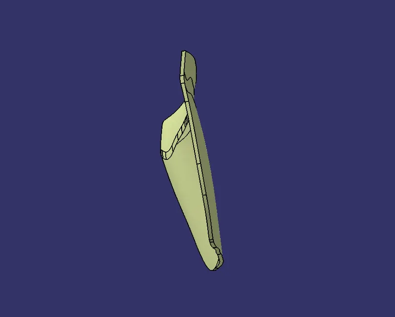
Top view
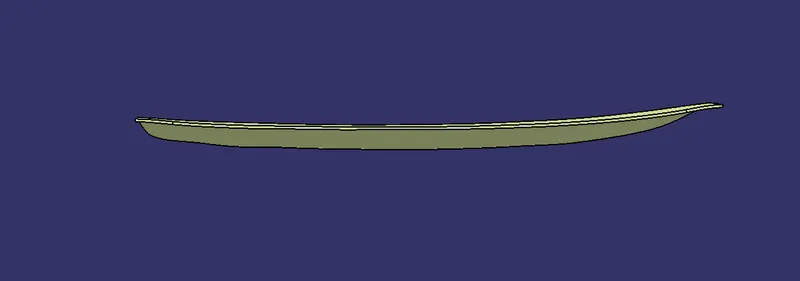
Isometric view
Door Applique Final Solid Body
Front view
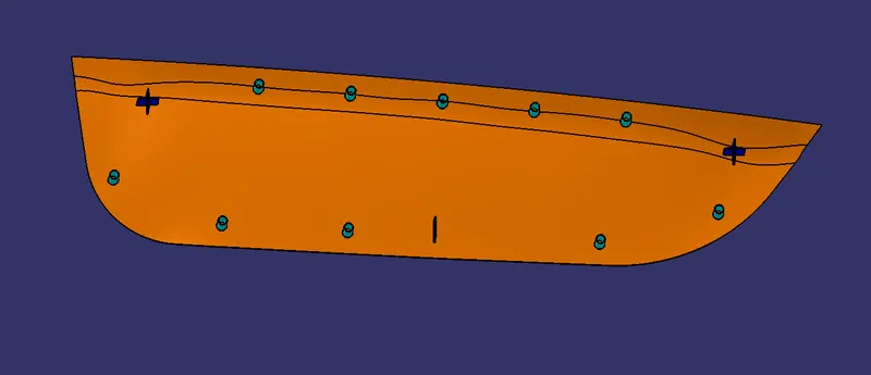
Side view
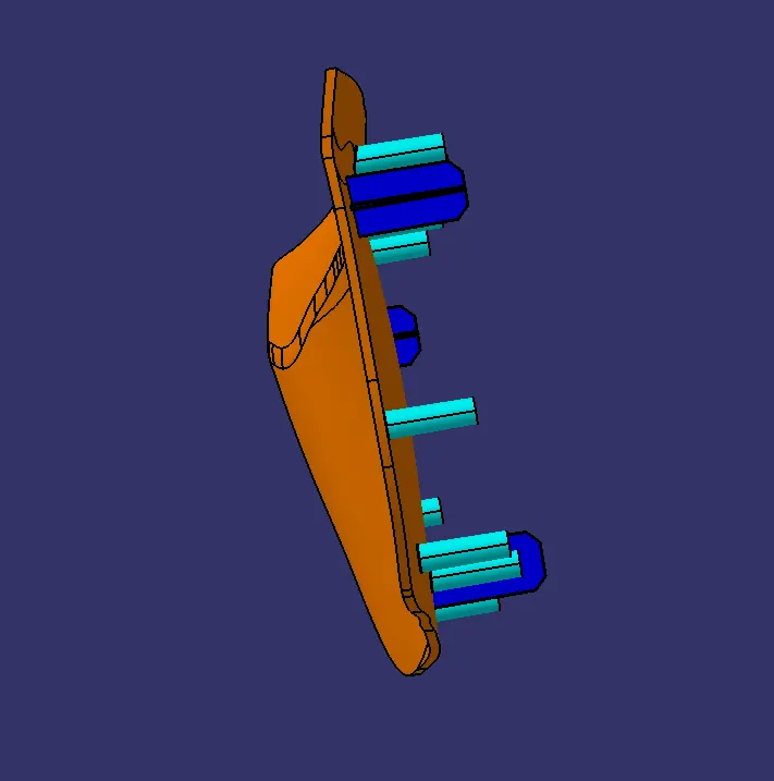
Top view
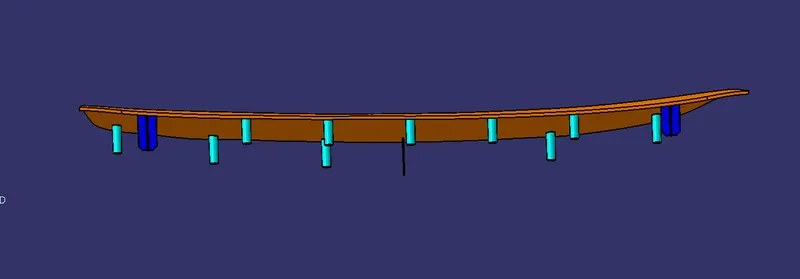
Isometric view
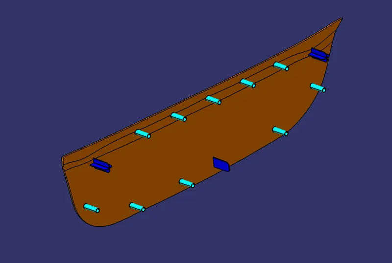
Door applique and door attachment assembly view