American Chopper Bike Assembly and Rendering
AMERICAN CHOPPER BIKE
Objective: To learn and apply different SOLIDWORKS commands/features to design an American Chopper Bike and render it.
Introduction: This report contains details about design of American Chopper bike using SOLIDWORKS, PhotoView 360, SOLIDWORKS Visualize. SOLIDWORKS is a 3d CAD design software and it was used in this project for modeling all the bike components and assemble them using proper mates and relations. PhotoView 360 is a visualization and rendering tool for creating photo-realistic renderings of your designs. SOLIDWORKS Visualize is a tool used to turn your CAD data into realistic photo-quality images.
Design Methodology:
The steps followed in the process are as follows,
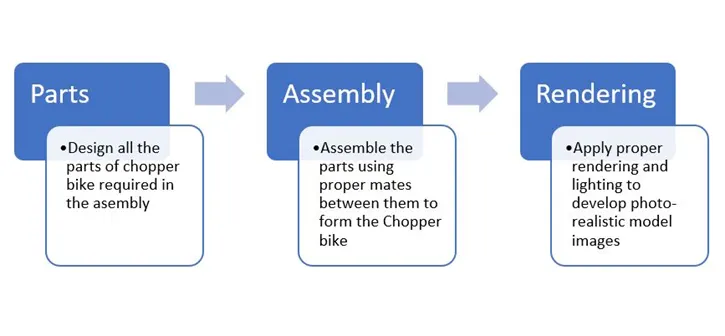
Fig.1 Design Methodology Flowchart
As bikes have various components, first we need to design all the components of the bike. Then in order to design the bike, we need to assemble all the parts with proper mates (relations) between them, to form the assembly. Further the assembly is given appropriate appearances and lighting effects to produce photo-realistic rendering images of the assembly.
Tools and Features:
- Chamfer: Chamfer is used to give a sloped or angled corner to otherwise sharp edge.
- Combine: Combine feature allows you to add two bodies together and keep the area that is common to both.
- Dome: As the name suggests, dome feature is used to provide dome shape to surfaces.
- Extrude: Extrude feature allows to form 3D solid body from surface or plane.
- Fillet: Fillet is used to give rounded shape to (internal or external edges) otherwise sharp edges.
- Loft: Loft feature allows you to generate complex geometry in a single feature by specifying cross sections made from faces and profiles of closed sketches.
- Mirror: As the name suggests, mirror feature allows you to create an opposite hand version of a part.
- Pattern: Pattern tool allows you to create patterns of desired parts/sketches along open or closed curves, edges, surfaces etc.
- Projected curve: This tool allows you to create a projected curve, from 2 different curves. The resultant curve is the intersection of surfaces formed by the two curves.
- Revolve: This feature allows you to revolve a closed sketch around a selected axis of rotation to form solid body.
- Shell: Shell tool hollows out a part and creates thin-walled features on all sides, leaving the selected faces open.
- Split surface: As the name suggests, split surface feature allows you to split a surface into two separate surfaces.
- Surface knit: Surface knit feature is used to merge 2 surfaces into one surface.
- Surface loft: Surface loft feature is used to generate complex surfaces by specifying cross sections made from sketches.
- Surface sweep: As the name suggests, sweep surface command allows you to sweep a surface along a given curve, to form a complex surface geometry.
- Sweep: Sweep command is used to sweep a feature along a provided curve to form a solid body.
Description:
Parts of the Chopper Bike:
- Chain
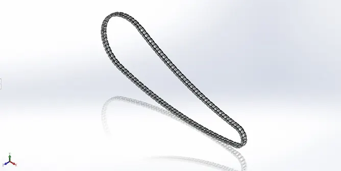
Fig.2 Chain
Chain is used to transmit power from the engine to rear wheel through sprockets. The features used for modeling the chain are,
- Extrude
- Pattern
- Mirror
- Fillet
- Chassis
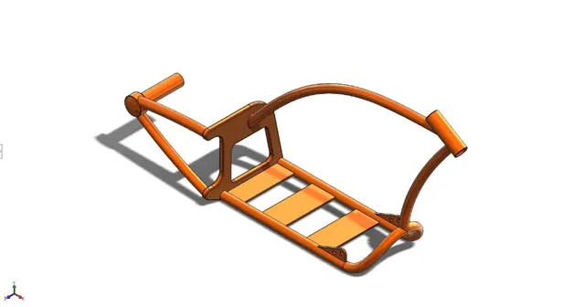
Fig.3 Chassis
Chassis is the supporting frame of a vehicle on which various components of the vehicle are mounted. The features used for modeling the chassis are,
- Extrude
- Mirror
- Fillet
- Chamfer
- Dome
- Sweep
- Split
- Combine
- Revolve
- Engine
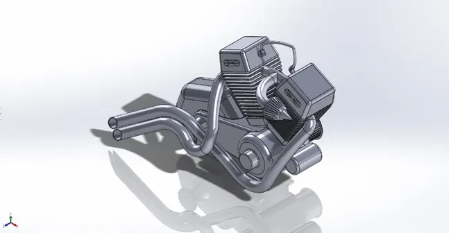
Fig.4 Engine
Engine is the power source of a vehicle. The features used for modeling the engine are,
- Extrude
- Revolve
- Dome
- Fillet
- Chamfer
- Pattern
- Mirror
- Split
- Combine
- Sweep
- Front Fender
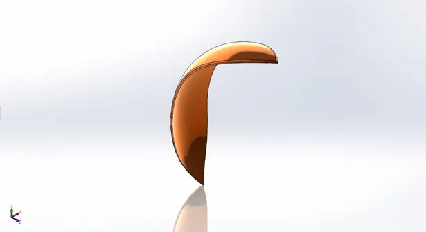
Fig.5 Front Fender
The primary purpose of the fender is to prevent mud, dust and rocks from being thrown towards the rider or bike components. The features used for modeling the front fender are,
- Revolve
- Split
- Fillet
- Front Fork
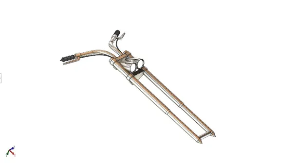
Fig.6 Front Fork
The front fork connects wheel and axle to the vehicle chassis. The features used for modeling the front fork are,
- Revolve
- Extrude
- Pattern
- Dome
- Fillet
- Sweep
- Projected curve
- Combine
- Front Wheel
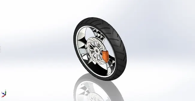
Fig.7 Front Wheel
Front wheel helps to turn the vehicle while moving. The features used for modeling the front wheel are,
- Revolve
- Extrude
- Fillet
- Pattern
- Chamfer
- Gas Tank
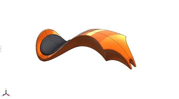
Fig.8 Gas Tank
Gas tank holds the fuel and form important point of contact between bike and rider. The features used for modeling the gas tank are,
- Surface sweep
- Surface trim
- Projected curve
- Surface loft
- Split line
- Mirror
- Surface knit
- Fillet
- Shell
- Kickstand
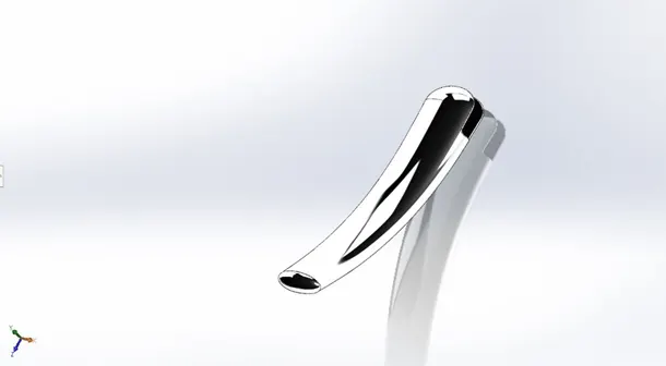
Fig.9 Kickstand
Kickstand allows the bike to stand upright without any external support. The features used for modeling the kickstand are,
- Loft
- Dome
- Extrude
- Split
- Fillet
- Oil Tank
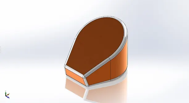
Fig.10 Oil Tank
It simply holds the oil. The features used for modeling the oil tank are,
- Extrude
- Combine
- Fillet
- Shell
- Pedal
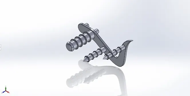
Fig.11 Pedal
Pedals are used to operate brakes or switch gears in the vehicle. The features used for modeling the pedal are,
- Extrude
- Fillet
- Dome
- Chamfer
- Pattern
- Rear Fender
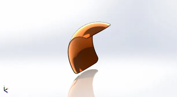
Fig.12 Rear Fender
The primary purpose of the rear fender is to prevent mud, dust and rocks from being thrown towards the rider or bike components. The features used for modeling the rear fender are,
- Revolve
- Split
- Fillet
- Shell
- Rear Wheel
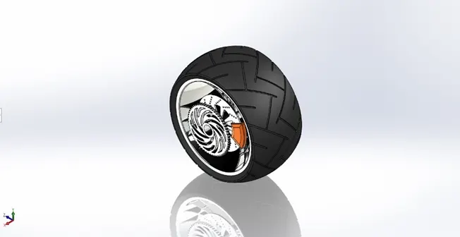
Fig.13 Rear Wheel
The rear wheel is the powered wheel in bikes. It propels the bike. The features used for modeling the rear wheel are,
- Revolve
- Extrude
- Pattern
- Combine
- Fillet
- Chamfer
- Transmission Belt
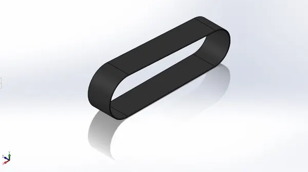
Fig.14 Transmission Belt
As the name suggests, main function of transmission belt is to transmit power. The features used for modeling the transmission belt are,
- Extrude
- Fillet
Assembly Views:
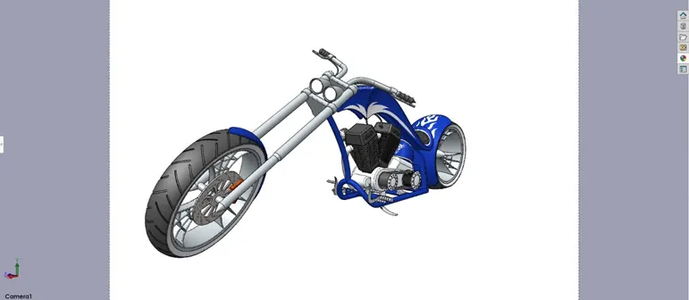
Fig.15 Camera View
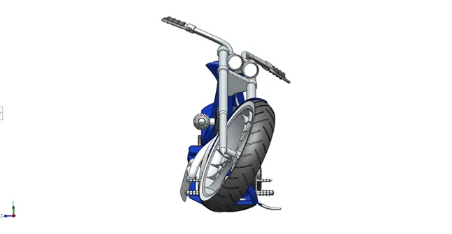
Fig.16 Front View
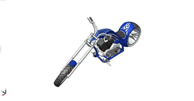
Fig.17 Isometric View
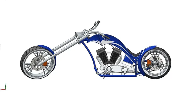
Fig.18 Side View
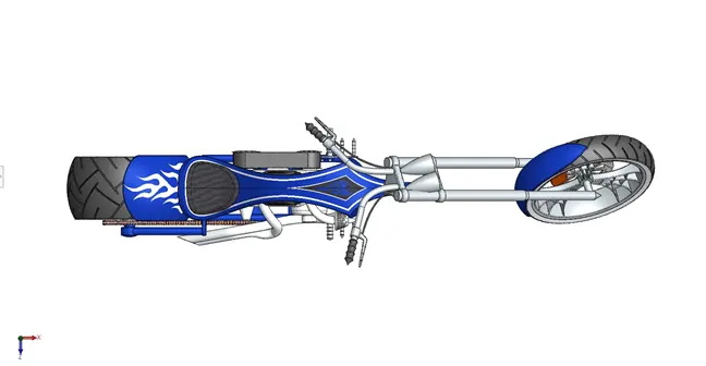
Fig.19 Top View
Rendered Images:
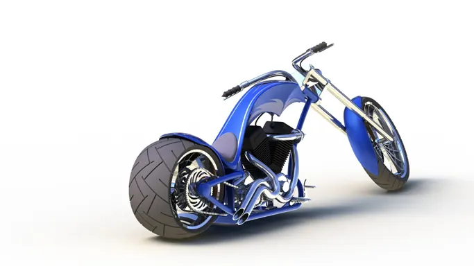
Fig. No.20 Render 1
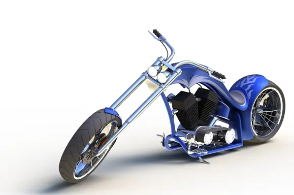
Fig. No.21 Render 2
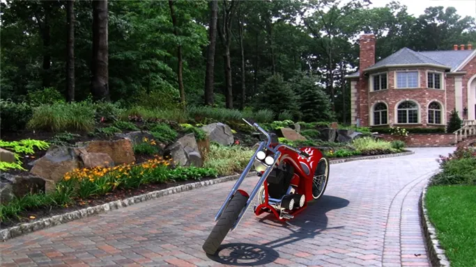
Fig. No.22 Render 3
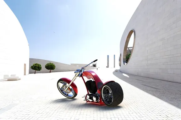
Fig. No.23 Render 4
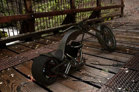
Fig. No.24 Render 5
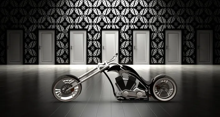
Fig. No.25 Render 6
CONCLUSION:
I used various commands and features in SOLIDWORKS to design an American Chopper Bike, and develop photo-realistic rendering for the same.