Car Roof Design
CAR ROOF DESIGN
Aim: To design car roof and its components with all given design parameters and perform curvature study for the same.
Car Roof and it’s Components:
- Roof –
The car roof is the portion of a car that sits above the passenger compartment. It protects the vehicle occupants or goods from sun, wind, rain and other external elements.
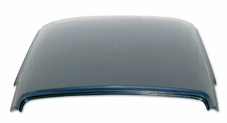
Fig.1 Typical Car Roof
- Components –
The components of the car roof are as follows,
- Roof panel
The roof panel is the large flat panel of the roof which rests on the roof rails and roof bows.
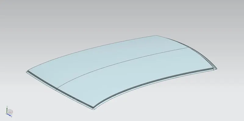
Fig.2 Roof Panel
- Front Roof Rail
Front roof rail is the sheet metal part that supports the roof panel at front.
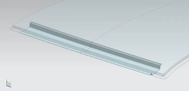
Fig.3 Front Roof Rail
- Rear Roof Rail
Rear roof panel is the sheet metal part that supports the roof panel at the rear end.
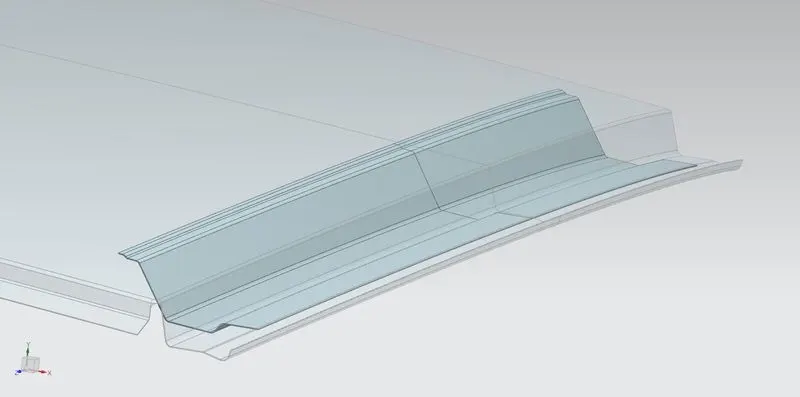
Fig.4 Rear Roof Rail
- Center Roof Rail
The center roof rail is present around the center part of the roof (not necessarily exact center) and supports the central portion of the roof panel.
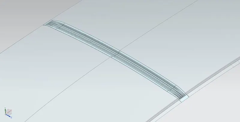
Fig.5 Center Roof Rail
- Bow Roofs
The bow roofs are sheet metal parts that are added to provide more strength to the roof. There may be more than 1 bow roofs as per the design requirement.
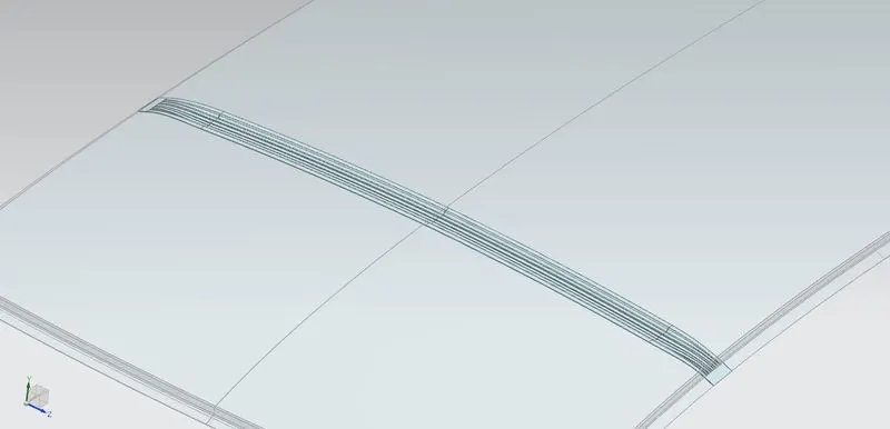
Fig.6 Bow Roof 1
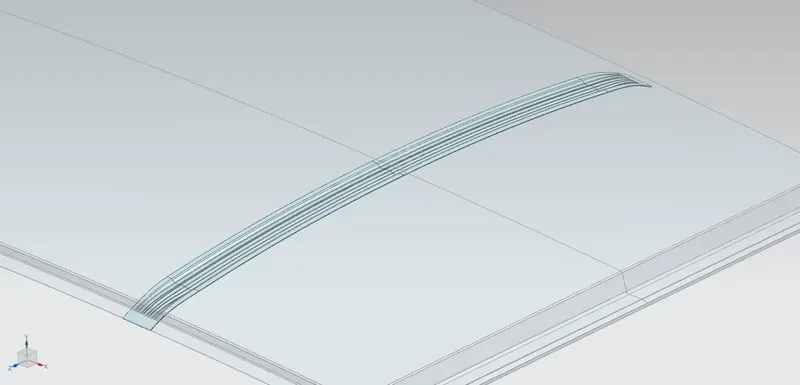
Fig.7 Bow Roof 2
Design Methodology:
To design the car roof, we are given a roof skin data from which we are supposed to start the design using that as the reference. First, we design the roof panel using the given roof skin data. We will create all other components of the roof inside assembly as they all are dependent on the roof panel. We have been provided with the master sections of parts as follows,
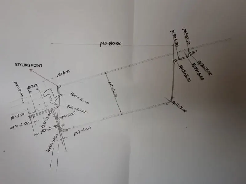
Fig.8 Front roof rail master section
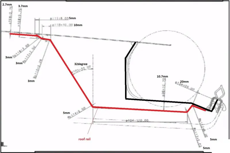
Fig.9 Rear roof rail master section
Then we design the front roof rail and rear roof rail taking the roof panel edges and surfaces as reference and with the help of master section and dimensions provided in it. After that we go for the center roof rail and the bow roofs which we have considered only 2 in our case.
After completing all the part designs, we go for draft analysis. Draft analysis is a tool used to determine of there are any negative drafts in the part. We have taken minimum draw angle of 7 degrees for analysis. The results of Draft analysis of required parts are given below.
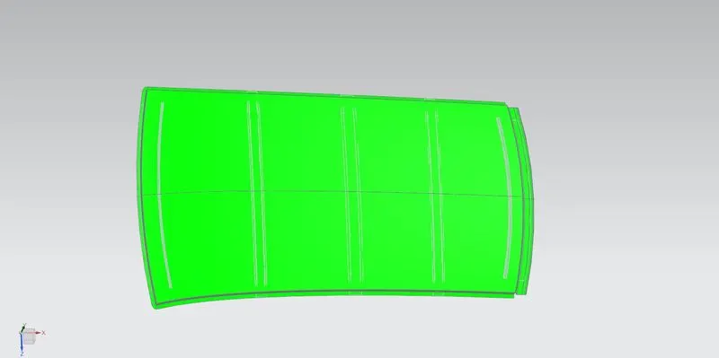
Fig.10 Roof Panel Draft Analysis
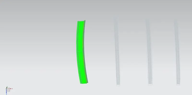
Fig.11 Front roof rail Draft Analysis
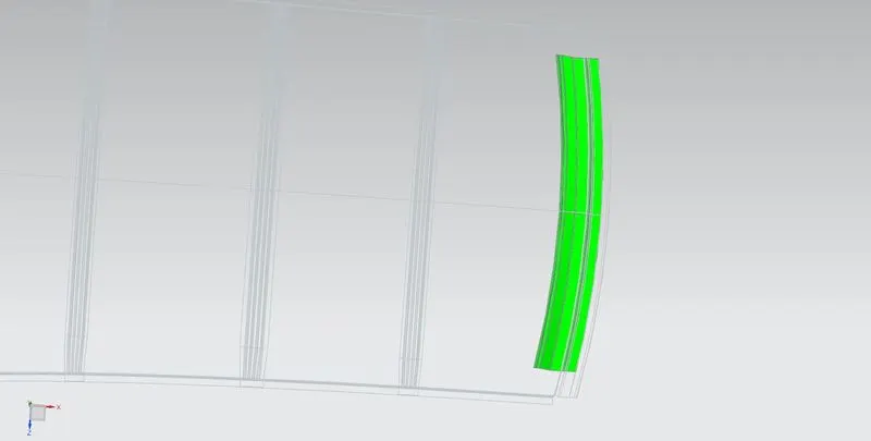
Fig.12 Rear Roof Rail Draft Analysis
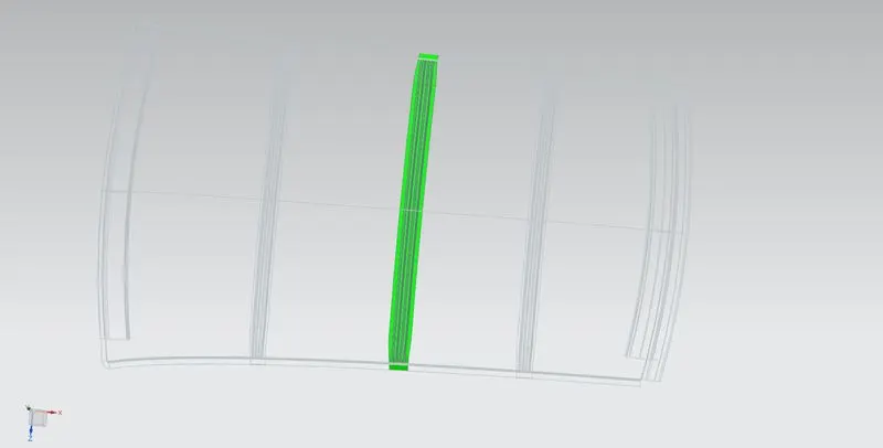
Fig.13 Center Roof Rail Draft Analysis
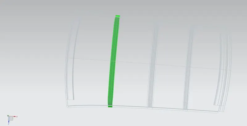
Fig.14 Roof Bow 1 Draft Analysis
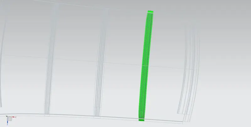
Fig.15 Roof Bow 2 Draft Analysis
Curvature Study:
- Moment of Inertia (Section Inertia Analysis)
The results for section inertia analysis for parts are as follows,
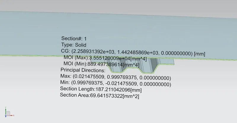
Fig.16 Section Inertia Analysis for Center Roof Rail
Minimum moment of inertia for center roof rail is 889.4974 mm^4.
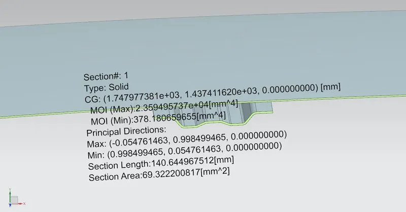
Fig.17 Section Inertia Analysis for Roof Bow 1
Minimum moment of inertia for bow roof 1 is 378.1806 mm^4.
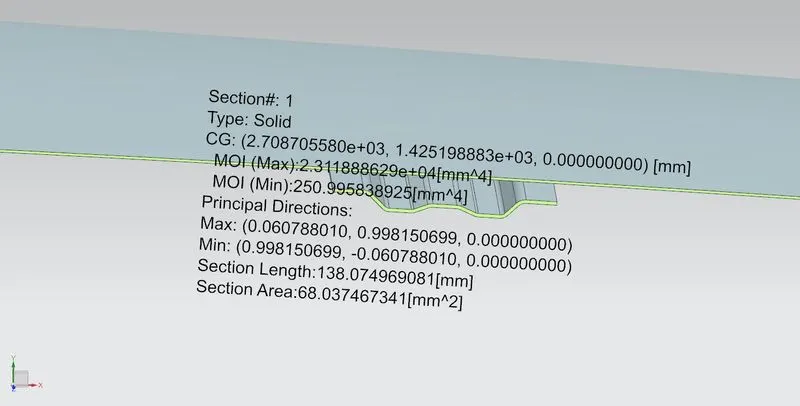
Fig.18 Section Inertia Analysis for Bow Roof 2
Minimum moment of inertia for bow roof 2 is 250.9958 mm^4.
- Heat Distortion
Heat distortion test is performed to determine if reinforcement is needed or not and to justify the reinforcement positions on the roof panel. We consider following formula under the heat distortion criteria.
Prediction formula:
W = 1.73*(10^-3)*L + 1.85*(10^-8)*(R^2/t) + 1.10*(10^-3)*l – 2.68
In above formula,
L: Roof length in X direction [mm] (dimension at 0Y)
R: Roof Curvature
R = 2(Rx*Ry) / (Rx+Ry)
Rx: X curvature
Ry: Y curvature
t: Roof plate thickness [mm]
L: Bow roof span [mm]
Where the judgement condition is based on value of W,
OK < 2.7mm ≤ NG
If the value is in range of 2.7 ≤ W < 3.5, we can provide outer panel reinforcement. We calculate the value of W at multiple points. We obtain these points by dividing the roof panel along its 3Y section (section at 300mm from center) in equal parts.
Calculating the required parameters:
To measure the parameters in the formula, we divide the panel into equal parts as shown in sketch below. We get 4 points at intersection of the section plane and the dividing lines. Then we offset the center line at each point on either side by 100mm and get 2 points on either sides of each of the initial 4 points.
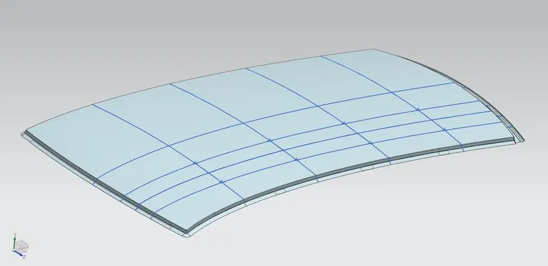
Fig.19 Dividing the panel into equal parts at 3Y section
Then we take the values of Rx and Ry between these points shown highlighted in above image. We measure these values using ‘Local Radius’ feature under Analysis tab.
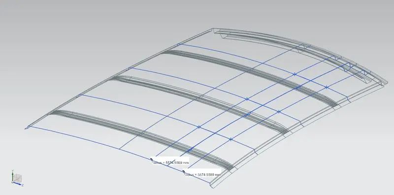
Fig.20 Measuring Rx for first point
Similarly, we measure the 3 other values at each point. Then we measure Ry for first point as below.
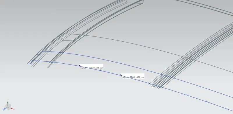
Fig.21 Measuring Ry for first point
Similarly, we measure the 4 other values for Ry. From these we get R value.
Then we measure L value as shown below,
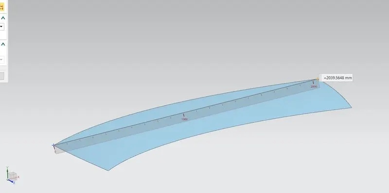
Fig.22 Measuring L distance
After taking all the values for all the points we can see the table below for reference of calculations and obtained values. You can use MS Excel to calculate all the values by inserting the formulas and values.

Fig.23 Heat Distortion Criteria (W) Values
As we can see, all the values for W lie in the given range, hence the considered positions for reinforcements are safe.
- Snow Load Condition
Now for snow load condition, we consider following formula,
Prediction Formula:
Qr = Iy*(t^2) / α*S*([(Rx+Ry)/2]^2)*(10^-8)
Where,
α = My*Lx2*(10^-12)
My = Y(Ly-Y)
Judgement Condition,
Qr ≥ 3.1
250 ≤ s ≤ 380
In above formula,
t: Roof plate thickness (mm)
Ly: Length of roof panel along 0Y (mm)
Lx: Distance between right and left end of the roof on each roof bow/ roof rail (mm)
Y: Distance between roof rail/ roof bow centers lying on either side of corresponding point (mm)
s: Distance for which roof bow bears divided load (mm)
s = L1/2 + L2/2
Iy: Geometrical moment of inertia of roof bow at 0Y cross section (mm^4)
Rx: Lateral direction curvature radius of roof panel along Y cross-section on roof bow (mm)
Ry: Longitudinal direction curvature radius of the roof panel along X cross section (mm)
Then we measure all the corresponding parameters for snow load condition, in the same way as mentioned above (heat distortion criteria), except by performing the calculation at 0Y section instead of 3Y section as in Heat distortion criteria.
After measuring all the values, we can refer to following table for calculation results.

Fig.24 Snow load condition (Qr) calculation
As we can see, One of the Qr values is not under the given range.
Conclusion: The design of roof and all components was performed based on given data. It was found that the design fulfilled heat distortion criteria condition. To avoid the out of range Qr value and get it into required range for one condition in snow load criteria, it is recommended to add embosses to the rear part of roof to increase local strength and hence the Qr value.