Week 9 - Project 1 - Door Applique Design with Engineering Features
Aim:-
The goal is to construct a door applique design from the given class A surface and engineering features to fit the component in the main surface.
Introduction:-
Engineering features are extensions on plastic components such as ribs, screw bosses, heat stakes, locaters, and so on that help secure the plastic component to the main surface and avoid plastic faults during the moulding process.
For the component shown below, functionalities such as locators and heat stakes are to be added.
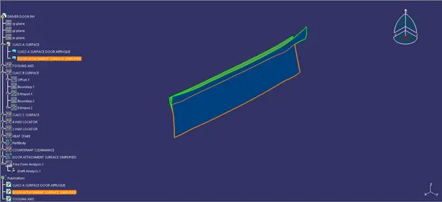
1. Examine the component for any surface holes and repair them if necessary.
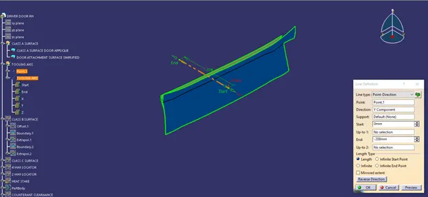
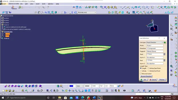
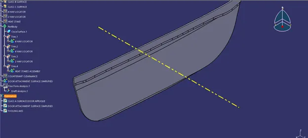
2. Follow the instructions below to create a tooling axis for the class A surface.
- Make a point in the centre of the component.
- Make a line perpendicular to the surface, with the newly produced point as its base.
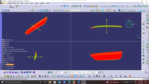
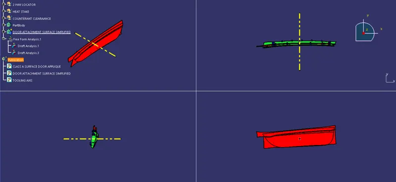
- The surface will be subjected to a draft analysis. Click on the surface after placing the axis on the formed line. The surface will be highlighted in green, blue, and red.
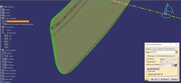
Take a offset of class a surface of 2.5mm to craete class B surface.
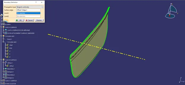
Apply boundary.
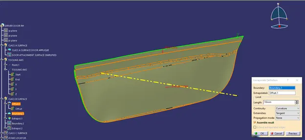
Extrapolate the boundary.
Same is done with the lower boundary.
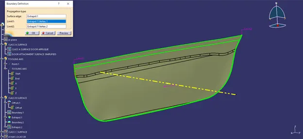
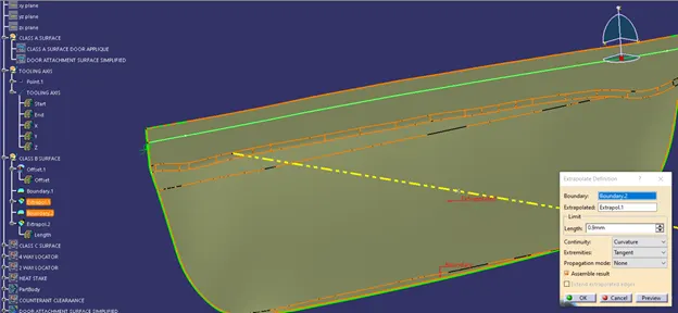
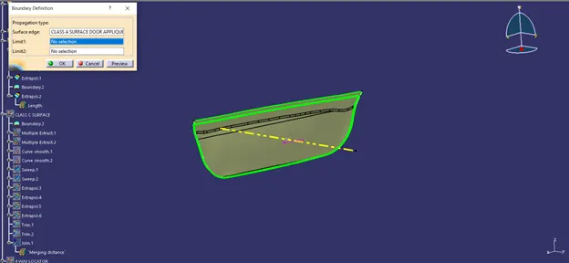
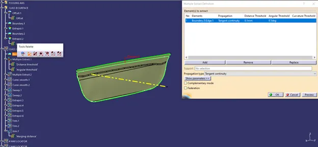
Now extract the boundary for making class C surface.
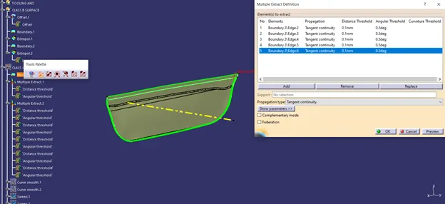
Use curve smooth to smoothen the curve which we extracted it.
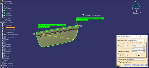
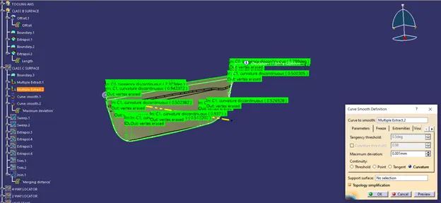
Now use sweep.
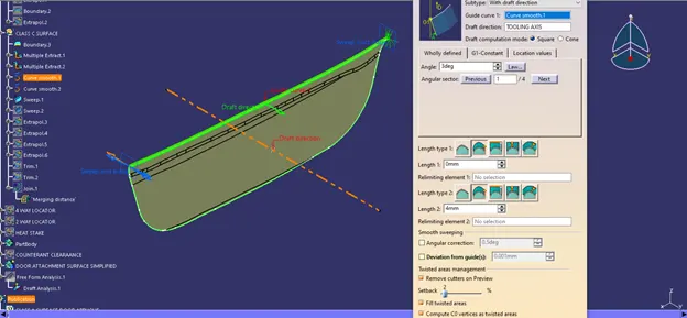
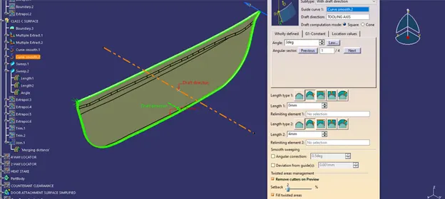
Extrapolate the sweep for trimming.
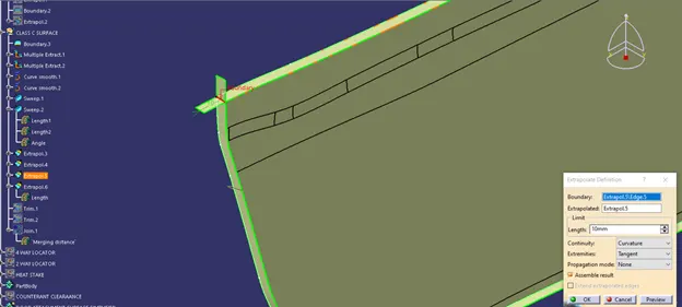
Trim the excess part.
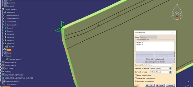
now trim it with the b surface.
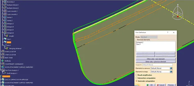
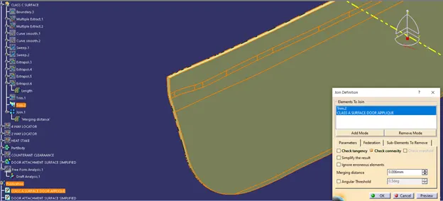
Now convert it to solid.
Locators:
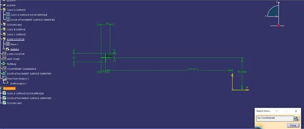
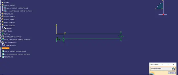
- Locators are used to locate a job or a component to arrest its degrees of freedom using the 3-2-1 Principle, which is the arresting of three degrees of freedom first, then two degrees of freedom, and finally the last degree of freedom in a sequence.
- A four-way locator will resemble an's,' whereas a two-way locator will resemble a 'a.' Both of these locators adhere to the same Rib Design Rules and principles.
- These Locators are installed on the B side of the component and must be the same height as the B surface.
- Heat Stake:
When producing items including Thermoplastic Components, it is frequently essential to link a thermoplastic to a part made of a contrasting material, such as metal or another thermoplastic. - Heat staking is a method of assembly that involves the controlled melting and reformation of a plastic stud or boss to trap or lock another plastic or metal component of the assembly in place.
- To be fastened in place, the Plastic Stud protrudes through a hole in the component.
- Heated thermal tips are used to melt the top of the studs, filling the volume of the cavity and producing a head that locks the component in place.
- The head is formed by the incremental melting of plastic under constant pressure.
- The appropriate combination of heat and pressure is crucial while staking.
- In a nutshell, Locators identify the component and lock 11 degrees of freedom, whereas the Heat Stake is a Fixation that locks the Final DOF.
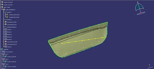
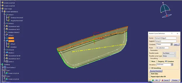
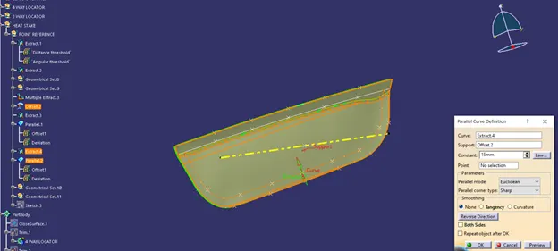
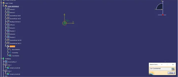
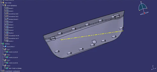
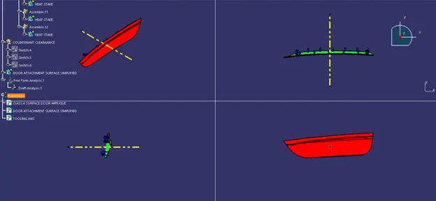
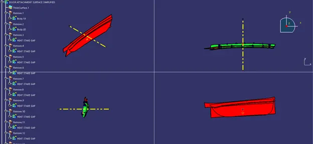
Thicken the door attachment surface.
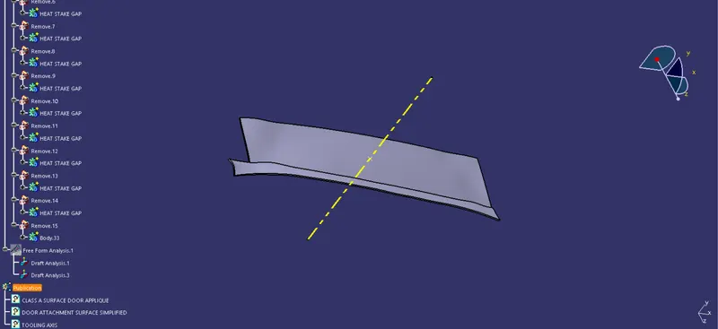
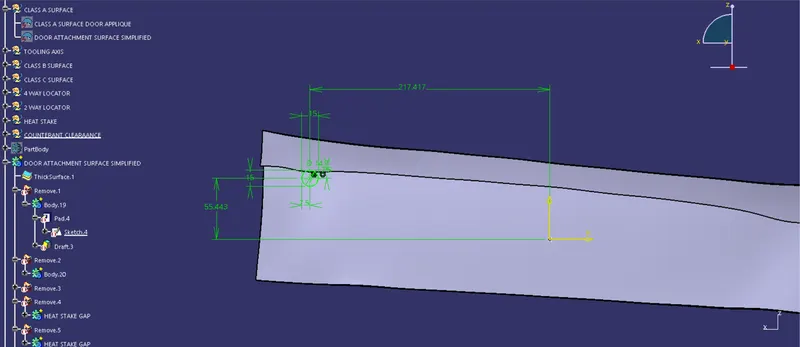
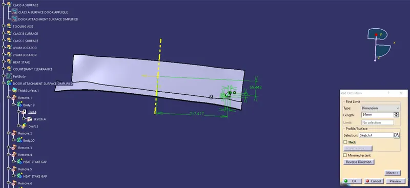
Drafts:-
- Draft is an angular tapering applied to every Plastic Component that must be fabricated during the design stage. It is offered in the Mold Movement direction.
- The Draft enables the parts to be easily removed from the mould without causing friction between the component's surface and the core and cavity plates.
- As a plastic component cools inside the mould, it has a natural propensity to shrink and adhere to the core or cavity half.
- The movement of the mould opening generates friction on the component's walls as well as the core/cavity blocks.
- This shortens the life of both the mould and the component.
- As a result, the component may have a rough surface finish and a fragile structure.
- This issue can be resolved by providing a draft to the component.
- While most applications demand minimum drafting angles of 0.5° to 1°, 3° drafting angles are typically allowed for cost-cutting purposes.
- Textured surfaces, such as instrument panels, are given a drafting angle of 7°. • Screw bosses, ribs, and stiffeners, due to their critical nature, are given the smallest drafting angles possible.
- Because 0° or negative drafting walls are difficult to construct, they must be redesigned from the Class A stage.
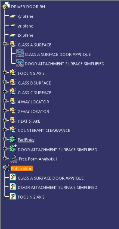
Geometrical set
Conclusion:-
The Design of Automotive Plastic Component --Driver Side RH Door Applique Design with 4-Way, 2-Way Locators and Heat Stakes has been
completed by using industry principles such as Rib design Rules, Draft Angles, Draft Analysis for Class A and Final enclosed surface, Tooling Axis
creation and implementation, Class B and Class C creation and conversion to a solid part.