Week 9 - Project 1 - Door Applique Design with Engineering Features
1) Objectives
*) To create heat stakes & locators for the door applique component considering design rules.
2) Requirements
*) Class A Surface
*) Tooling Axis
*) Part Thickness
3) Procedure
A) Creation of Tooling Axis
*) Create the tooling axis for Class A surface which meets the requirement of draft angle.
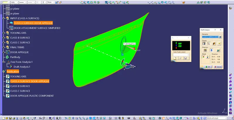
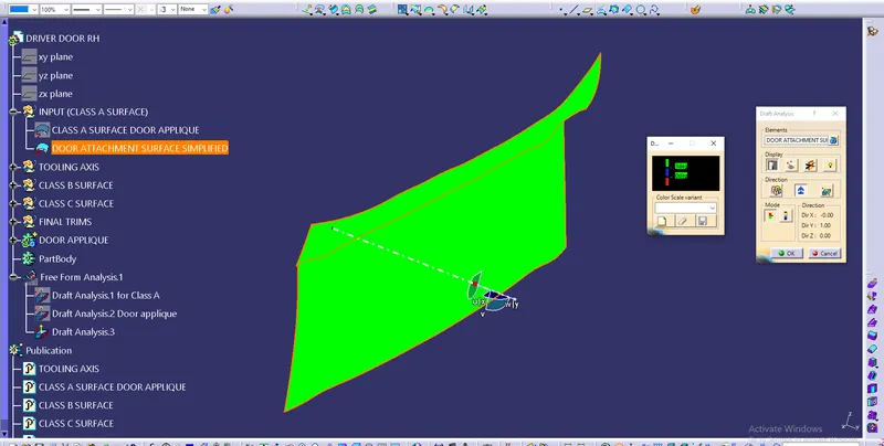
*) The following are the images of Draft analysis of Class A surface along Tooling Axis
B) Class B & Class C Surface Creation
*) Create Class B Surface by offsetting Clas A by 2.5mm & also create Class C Surface
*) Join Class A & Class C together & further trim with Class B to get plastic component.
*) Use Closed surface to get solid plastic component.
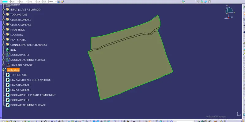
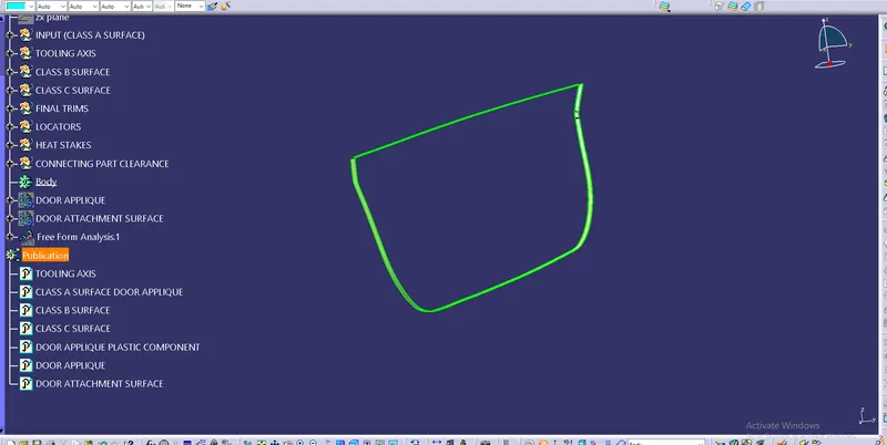
*) Following are the images of Class B & C & final llastic component.
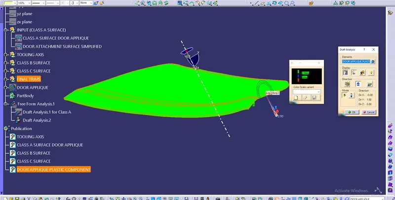
*)Following are the images of Draft analysis for the door applique plastic component
C) Creation Locators & Heat Stakes
i) Locators
*) locators are the attachment/fixing features which in fixing a component at defined positio in an assembly.
*) Make sure the tip of all locators are at the same height from the surface to which they are attached.
*) Give min. 0.5° Draft Angle for all the faces pf locators
*) Chamfer the entry face of the locators.
*) Consider min. 0.1mm of Clearance between hole and the locator.
ii) Heat Stakes
*) Heat stakes are the fixing feature attached after assembly.
*) The height of the heat stakes should be lower than the locators.
*) Give clearance of min. 0.5mm with the connecting feature.
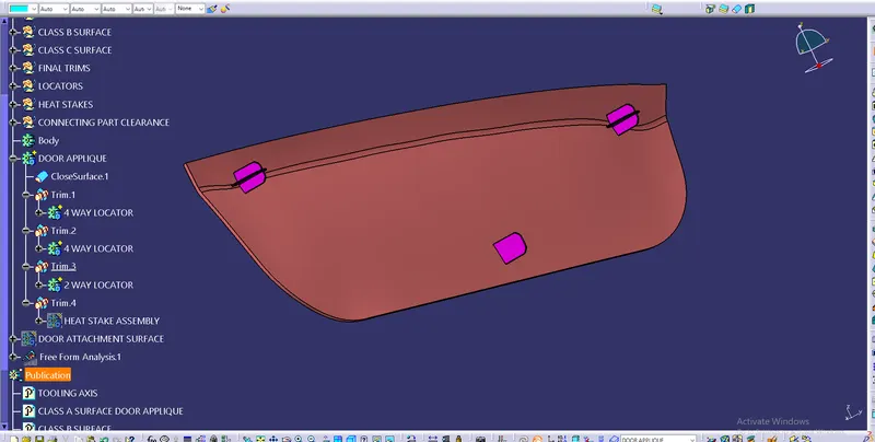
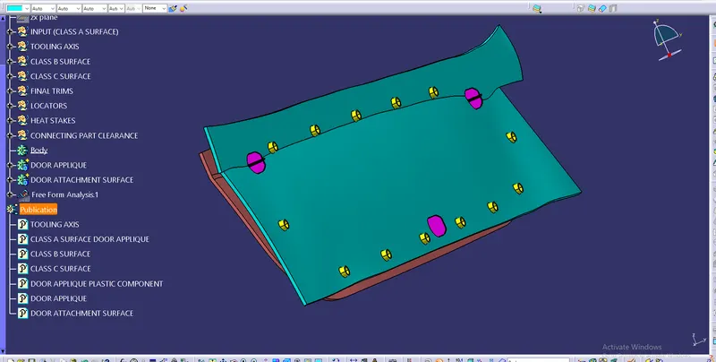
*) Following are the images of heat stakes and the locators
4) Conclusion
*) Locators and Heat stakes are created for the Door Applique plastic component considering all design rules and it is meeting the requirement of draft angle.