Week 8 - Challenge 3 - Switch Bezel Design
1) OBJECTIVES
Creation of a Switch Bezel plastic component using given Class A Surface and to perform Draft analysis on the model.
2) REQUIREMENTS
The following are the requirements to create switch bezel.
*) Class A Surface
*) Tooling Axis
*) Thickness of the component given as 2.5mm.
3) PROCEDURE
A) Creation of tooling axis
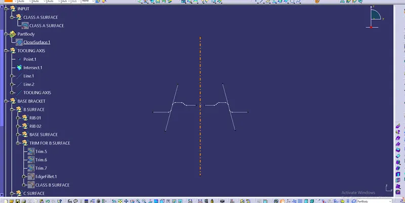
*) Tooling axis is the direction in which mold opens and closes. i,e the tooling axis should clear all the surfaces when it seen normally
*) The following images shows the creation of tooling axis using bisecting line.
B) Creation of Class B Surface
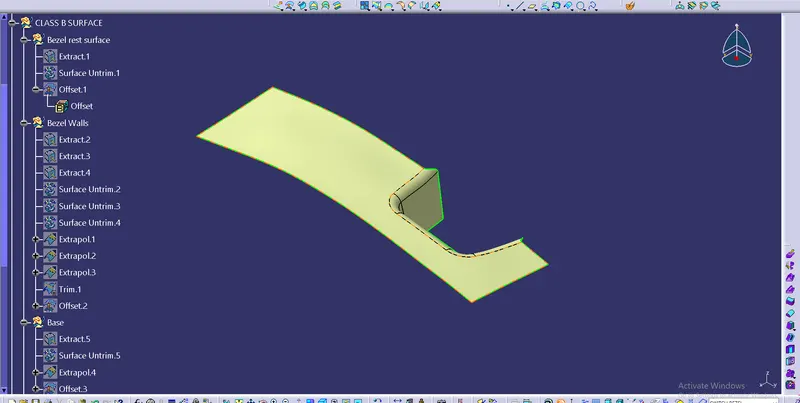
*) Class B is an Engineering surface of a plastic component, to which all the other fixing components are attached.
*) It is created from Class A surface by the use various commands required.
*) Fillet Values for class B should be given by considering wall thickness value, to form uniform wall thickness. Which further avoids the flow line on the final component.
*) Below image shows the Class B surface.
C) Creation of Class C Surface
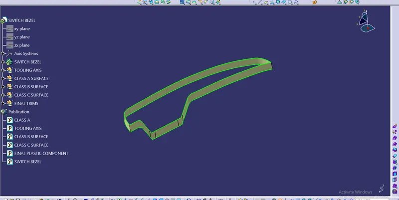
*) Class C surface is the surface which joins both Class A & Class B Surfaces to form Final component.
*) It is also created from Class A, using various commands, further joined with class A.
*) Finally the joined surface is trimmed with the Class B to get final component.
*) Make sure the final component doesnot have any discontinuities. Check with boundary command.
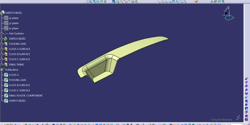
*) Make it Solid model using Closed surface.
*) the image shows the Class C surface & Final plastic component.
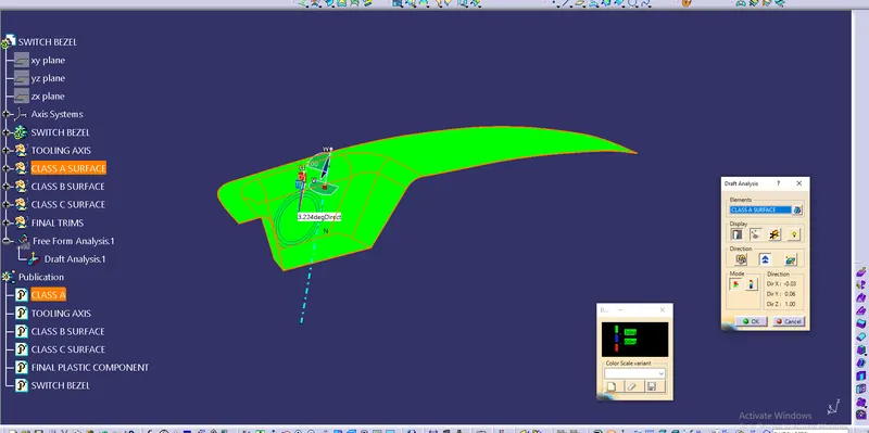
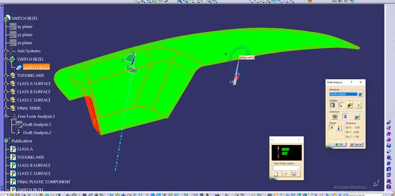
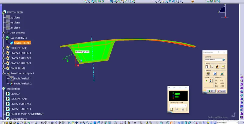
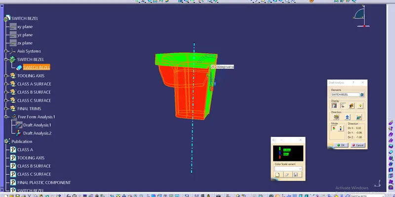
D) Draft Anlysis.
*) Draft is the amount of taper given for molded part which enables the part will be removed easily when the mold opens.
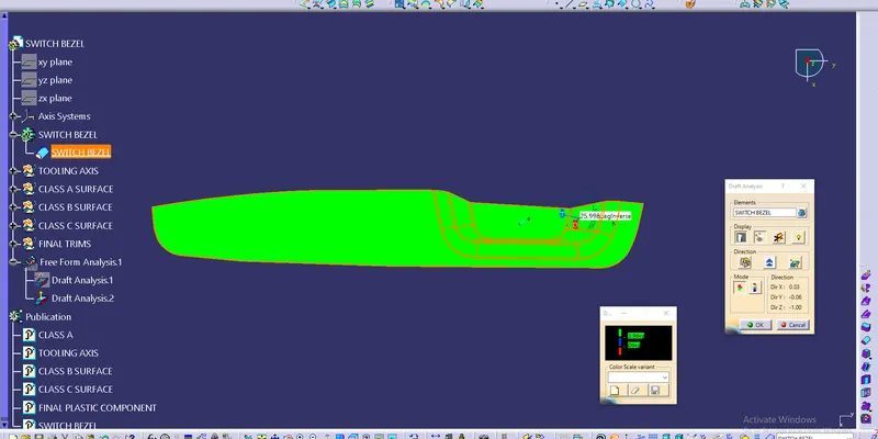
*) Draft analysis is prformed based on color ranges identifying zones.
*) The draft value is set and specified with different colors.
*) The given draft value for the component should be more than the set value.
*) The below images shows the draft analysis for Class A surface & the Final model in different View modes.
E) Tree Structures
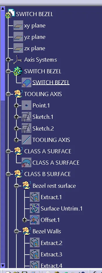
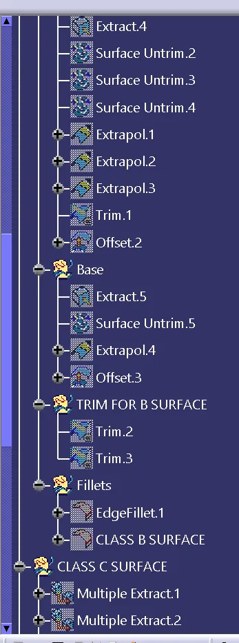
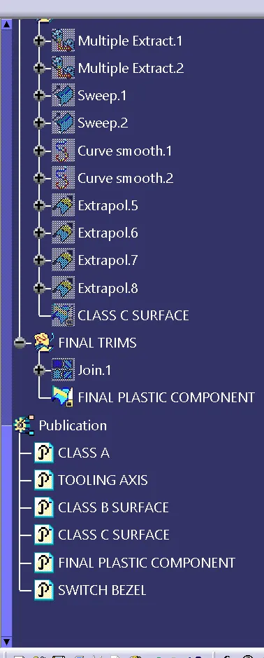
4) Conclusion
*) After draft analysis we conclude that the final plastic model Corresponds to the draft value specified, along defined tooling axis