Week 8 - Challenge 4 - Coin Holder Design
1) Objectives
*) To create a Coin holder plastic component through the given Class A Surface and to perform draft analysis.
2) Requirements
*) Class A surface
*) Tooling Axis
*) Component Thickness :- 2.5mm as given
3) Procedure
A) Creation of Tooling Axis
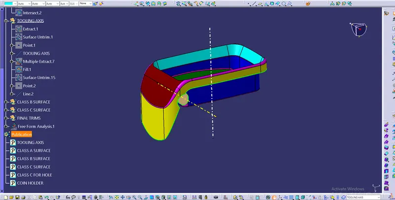
*) The tooling axis cannot be created using bisecting line method, because some of the side wall surfaces are exactly perpendicular to the base.
*) Since the Class A surface contains the large flat surface i,e bin base, create a tooling axis perpendicular to that surface.
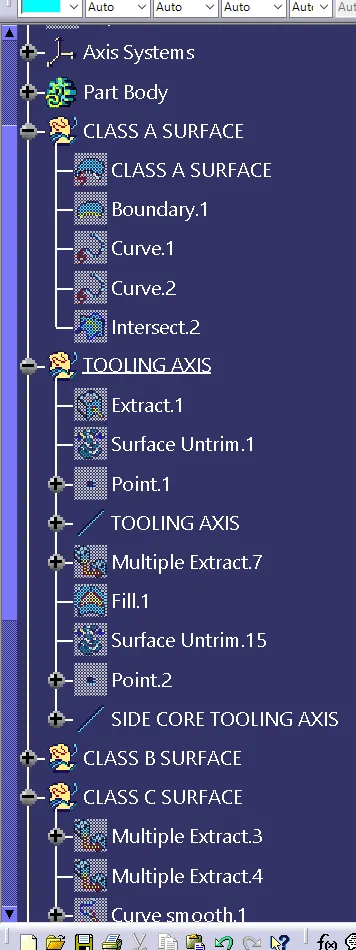
*) The hole in the component is cleared with side core tooling axis.
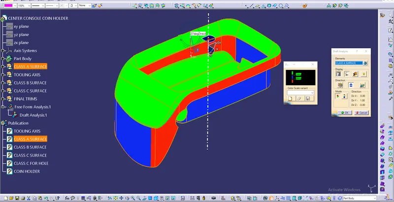
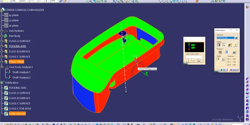
*) Since some sufaces of Class A are parallel to the tooling axis the draft analysis is not meeting the requirements.
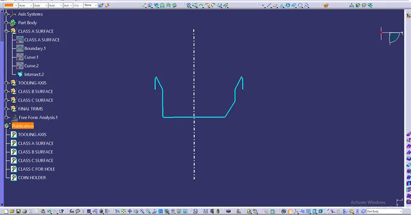
*) The below images shows the tooling axeses created & draft analysis for Class A surface.
*) The red surfaces are making negative draft angle with the created tooling axis, hence Class A surface need to be modified.
B) Creation of Class B Surface
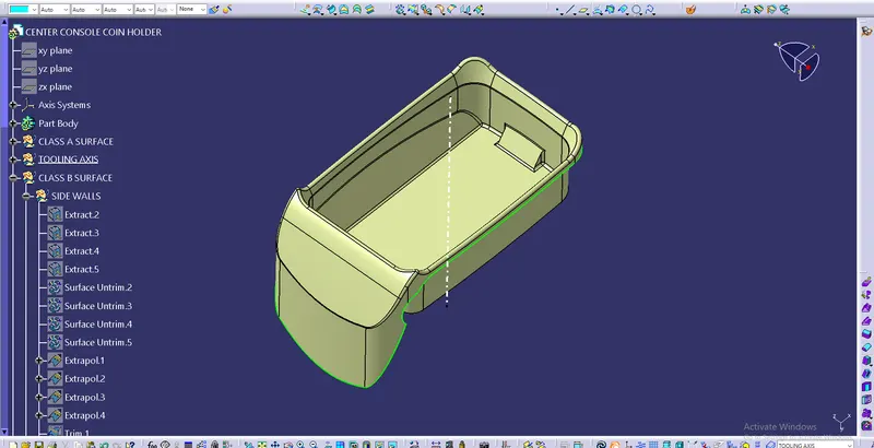
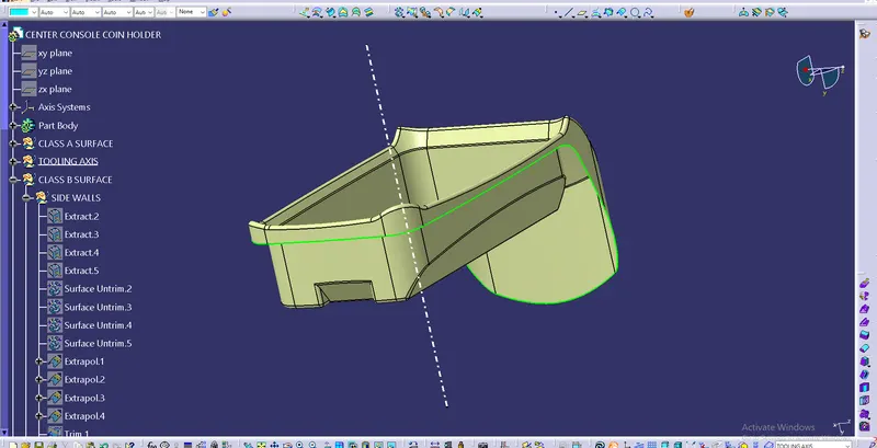
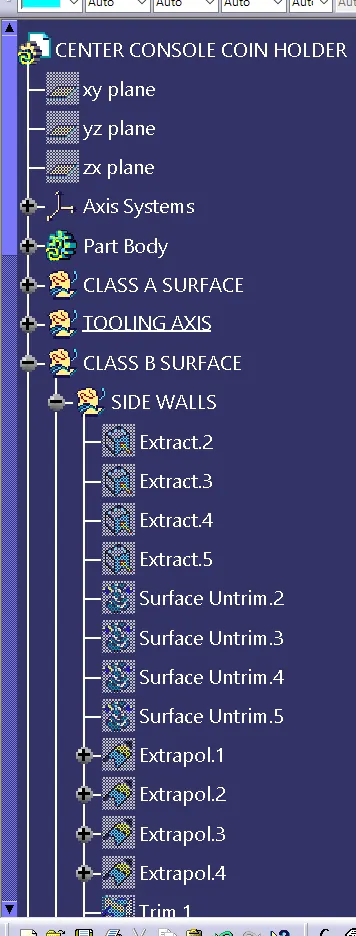
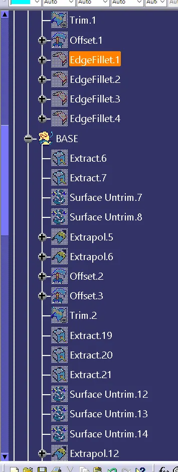
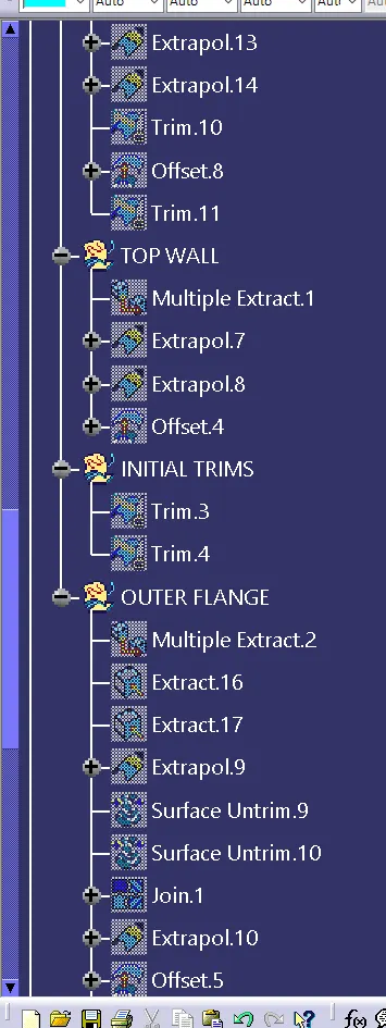
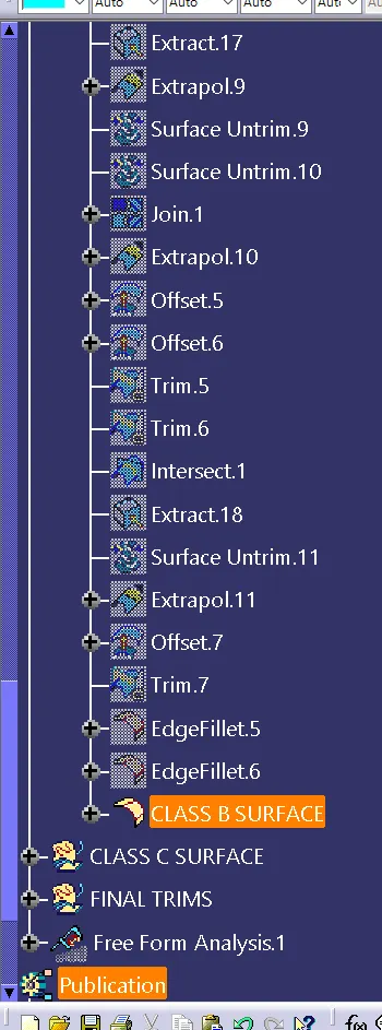
*) Create Class B Surface by offseting the Class A Surface and using various commands .
*) Make sure the Created class B surface is uniformly offsetted with 2.5mm thickness.
*) Fillet the corners by considering thickness & give min 0.5mm fillet radius whire it is not possible.
*) The following images shows the Class B Surface and tree structure.
C) Creation of Class C surface
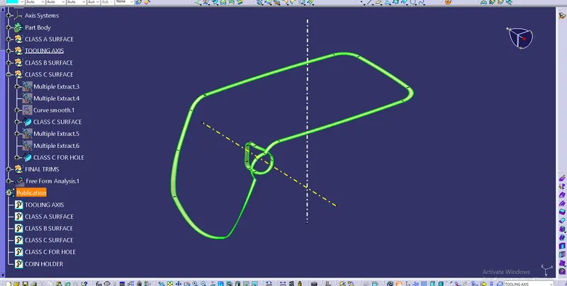
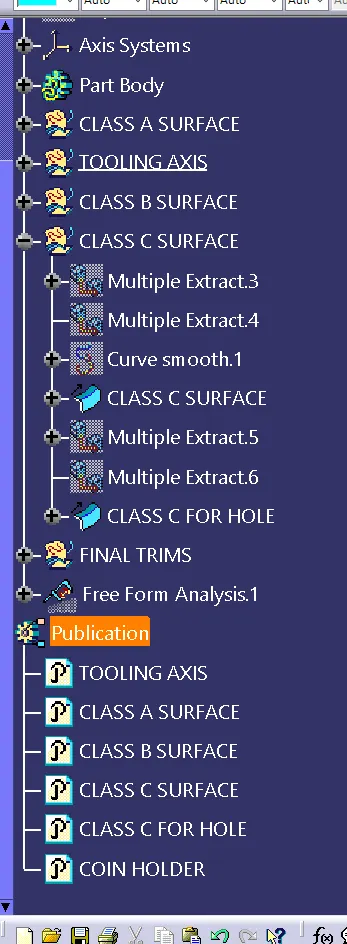
*) The Class C surface is created through Class A.
*) Extract the outer flange and its bounderies.
*) Create a surface perpendicular to thet extracted surface using sweep command with reference surface.
*) Also create C surface for the hole.
*) Following are the images of Class C surface & tree structure for the same.
*) Finally trim the class B & C surfaces & join with Class A.
*) Use close surface to form solid body.
D) Draft Analysis
*) Do draft analysis for the final solid model along the tooling axis.
*) Since some of the surfaces of Class A are parallel to the tooling axis the final component also not meeting the requirement of draft angle.
*) The below image shows the draft analysis for final plastic component, which is not meeting the requirement.
*) Hence the given Class A surface should be modified with draft angle.
4) Conclusion
*) The coin holder plastic component is created through the given Class A surface.
*) Since the tooling axis created is not meeting the requirement of draft angle as surfaces of Class A are parallel to that, the class A should be modified with draft angle, min of 3°.