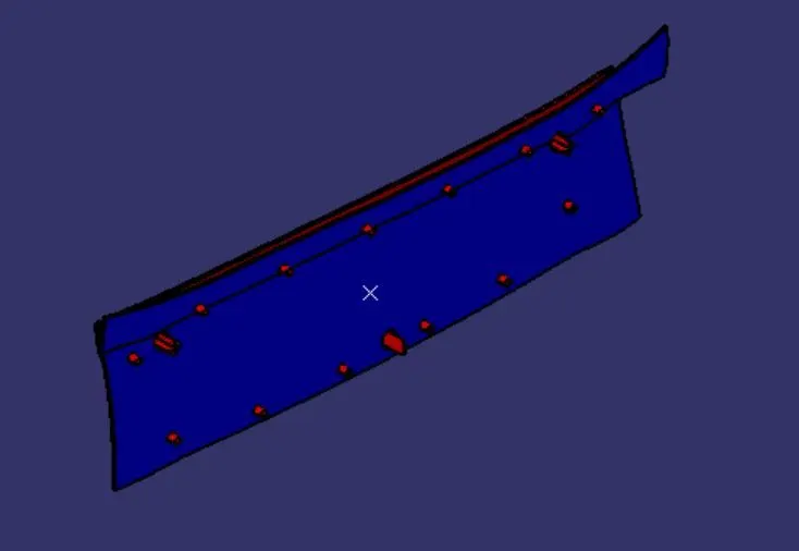
Week 9 - Project 1 - Door Applique Design with Engineering Features
Procedure To Design Door Applique Design with Engineering Features
Step -1: - To Design the Heat Stakes and Locators For the required component to restrict the unwanted rotations and Movements in the assembly of the Part.
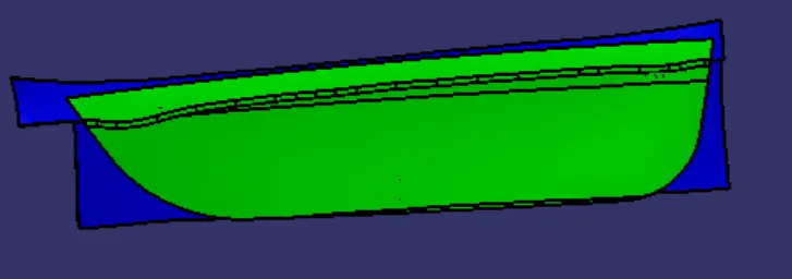
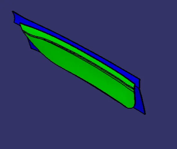
Step -2: - To start the Locator and Heat stakes add thickness to the class-A surface for the Door Applique and the Door attachment for the Door Applique add the Thickness of 2.5mm and For the Door attachment, 2mm and check the draft analysis for the Door Applique.
Step -3: - The Next step is to start with adding the Tooling Axis for the Door Applique to add the Locator and Heat Stakes features. For the tooling axis Create the Geometrical Set and name as Tooling Axis .and Extract the Class-A of Door Applique and make a point on it by using the surface mode in point command next to create the line go to line command select the point and direction option and select the Y-axis is the axis for creation of the line. in this case I directly took the perpendicular line to the face of Door Applique because there are no side features to create the Bisecting line method.
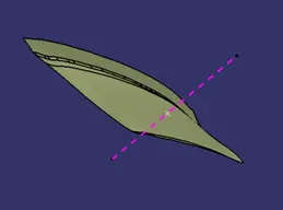
Step -4: - The Next step is to start the locator for the Door Applique create the new geometrical set and name as Locator in that create another geometrical set and name as 4 Way locator and create plane select the zx plane and open the plane command and select the point that created for the tooling Axis the plane was formed and add the positioned sketch with the help of new plane and the point in that sketch draw two lines perpendicular to each other. And the length of the line is 15mm.create the Part file and use pad for the sketch and having the thickness of 1.3mm a and adjust the height according to the Door attachment and Door applique. Then add the Draft for the 4 Way locator with 0.50 .and add the chamfer for the Free Entry with the length of 3mm and 450 angle then at the final add the minimum Fillets for the 4 way locator. To make another copy for the 4 way locator copy the main part body and past it then use the translate command to set the copy file and add to the Door Applique by using unitrim command.
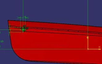
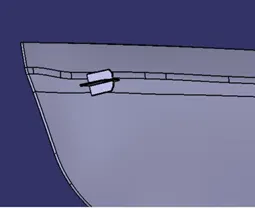
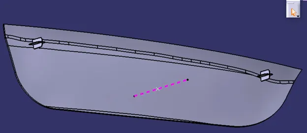
Step -5: - use the same process for the 2way locator to arrest the translate and rotate motion for the component .inset the geometrical set and name as 2-way locator and sketch the length of line and a pad the sketch and add Draft and Fillet and opening chamfer for the 2-way locator at the center of the component.
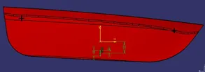
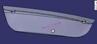
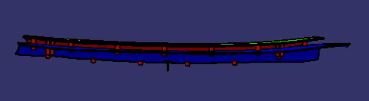
Step -6: - the next step is to create the Heat stakes to restrict the other translate motions for that create a Geometrical set and name as Heat stakes and extract the boundary surface of the Door Applique and offset to the height of the top surface with 2.5mm and parallel curve command and make a line up to 15mm from the outer surface of the applique and add a point on the sketch for that use the point and planes in the point command bar and select that successive point on the curve and make sure the gap between the two heat stakes are 50mm use the sketch for the creating the heat stakes and pad it to crate multiple features use the same method that used in above copy the feature and past it and use translate option with a point to point method for the multiple features and use the union trim the with the Door Applique.
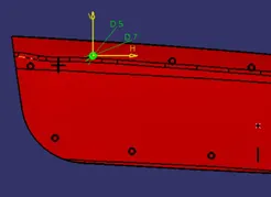
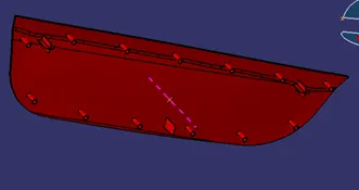
Step -7: - the next step is to add the clearance for the Locators and Heat Stakes and the minimum clearance is 0.1mm copy and use the same sketch in the locator and draw a circle with the dia of 30.2mm and insert the part file and pad the sketch and add the draft of 0.50and remove from the Door attachment part and check and adjust the clearance Between the Locator and the Door attachment fill and for multiple features copy the part file and past it and use translate the file to the location and remove from the Door Attachment. repeat the same process for the 2way locator and heat stakes to get the clearance and remove it from the Door attachment part file
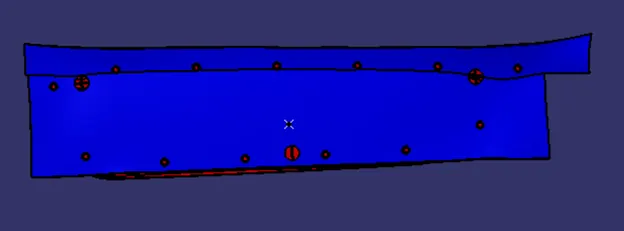
Step -8: - check the Draft analysis of the main component if there is any problem we can go to the previous step and rectify the problem. Draft analysis is also used to identify the problems in the component
For Draft, analysis selects the Draft analysis tool in the Analysis command prompt the draft analysis tool opens and sets the UCs icon lies on the Tooling axis and select the component and give an angle which required for the component for the appearance of the component.

Images