Week 9 - Project 1 - Door Applique Design with Engineering Features
Door Applique Design with Engineering Features
What is Generative Shape Design?
The Generative Shape Design provides an extensive set of tools for creating and modifying mechanical surfaces used in the design of complex shapes or hybrid parts, Its feature-based approach offers a productive and intuitive design environment to capture and reuse design methodologies and specifications. It helps to design advanced shapes that are based on a combination of wireframe and extensive multiple surfaces which includes high-level features with full specification capture and reuse.
What is Draft Analysis?
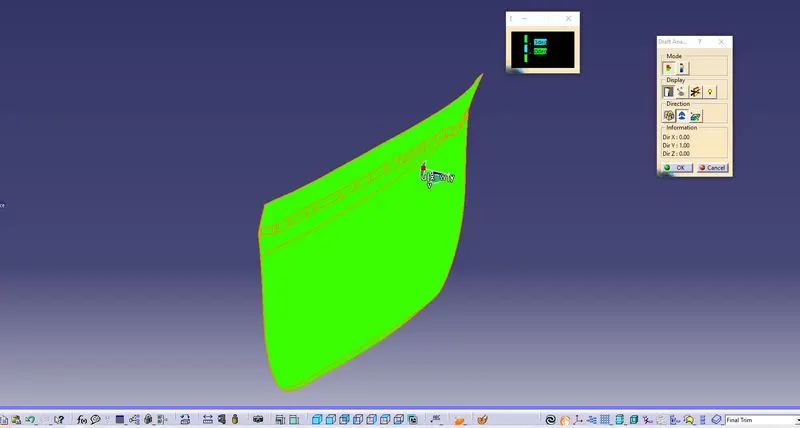
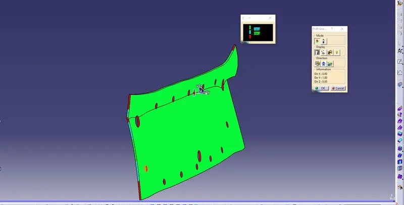
The Draft Analysis command enables you to detect if the part you drafted will be easily removed, this type of analysis is performed based on color images identifying zones on the analyzed element where the deviation from the draft direction at any point corresponds to specified values.
No parts can be ejected from the tool if it is having a straight 90-degree profile from its base surface, a small draft angle is provided to each area of the component to get easy removal of the component from the tool. The draft analysis technique is used to analyze whether our part model created in cad is manufacturable based on the draft condition applied.
In the molding process, the molded parts have to eject from the die so there are some issues while removing the molded parts it may get sticky with the die, or while removing the chances to get damaged, so we need to set up is the draft angle this draft angle helps the molded part to eject from the die easily.
What is Class A, Class B, Class C Surfaces?
Class-A Surface: Surfaces made by the designer which is given as an input to the plastic modeler to work on, it is aesthetic surface and the outermost surface.
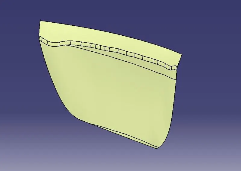
Class-B Surface: Surfaces made below a certain thickness from the Class-A surface is Class-B surface. This is the surface that contains engineering aspects of the model.
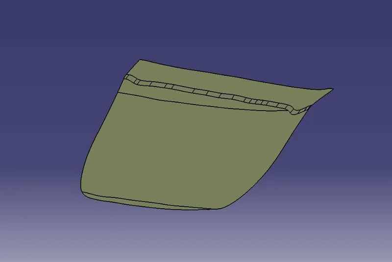
Class-C Surface: Surfaces that join Class-A and Class-B surfaces is Class-C surface.
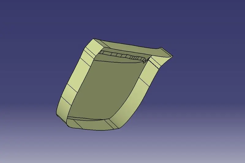
What are Locators and Heat Stakes?
Locators or Locating Pins:
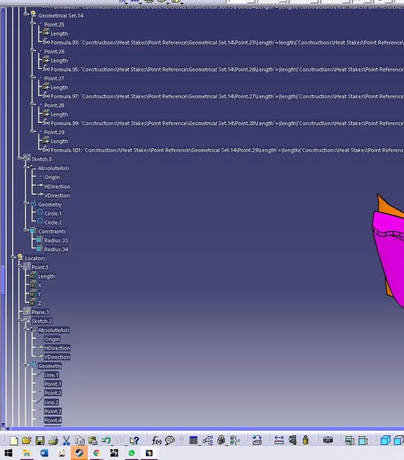
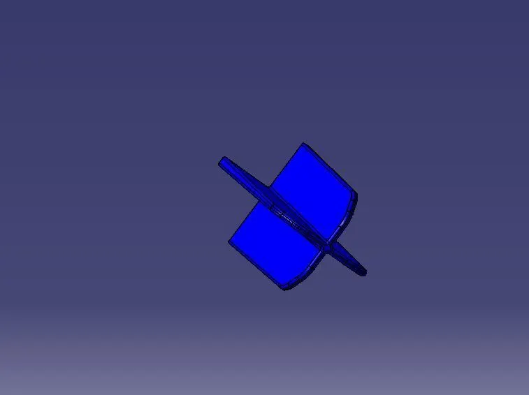
Locating pins are the rib-like structures on the B surface that are used to position the child part with the parent part while assembling. These locators were placed in multiple locations on the part depending upon the degrees of freedom that needs to be arrested. They were classified as four-way locators and the one which is like structure is the two-way locators.
Heat Stakes:
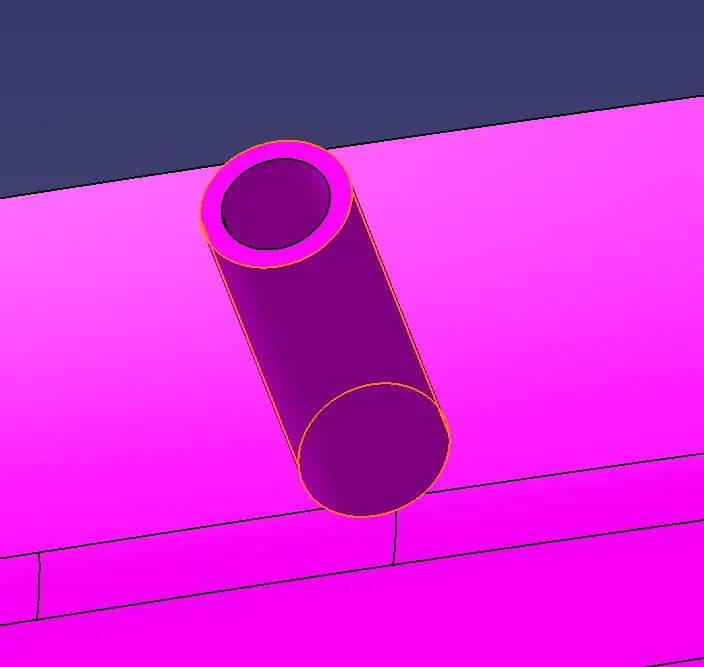
Heat Stakes are the vertical cylindrical structures added to the B surface. These are used to attach the child part with the parent part. This is joined to the parent surface by melting the heat stakes which protrudes beyond the attaching or parent part, which is called plastic welding. This kind of attachment provides the advantage of avoiding any additional fastening methods like bolting, Push clips, etc. which will add the weight of the component, but it has a disadvantage that once it is fixed it cannot be removed without damaging the component. Here, since we will not have any need for removing or replacing this applique, therefore, we are fixing it with heat stakes.
2 Way and 4 Way Locators
In any kind of assembly before fixing the part to the mating we need to fix the position of the part with the respect to the mating part. In these cases, we need to follow some engineering principles in this project we are going to follow the 3-2-1 principle, any part which has to be fixed during the welding or machining process has to be fixed is having 12 degrees of freedom.
Procedure
- First import the Class A surface of Door Applique model in Catia V5
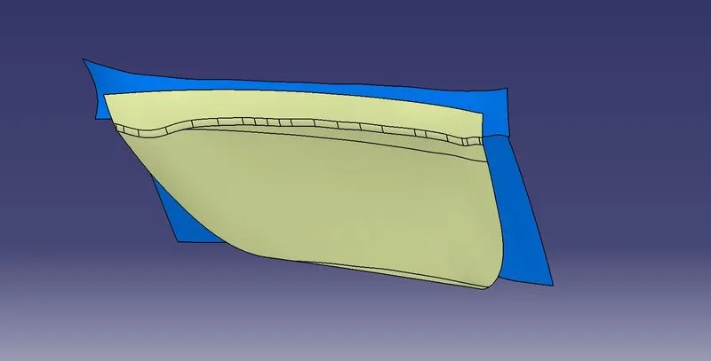
- Check the connectivity of Class A Surface using the boundary option. Ensure that there is no gap between the two surfaces.
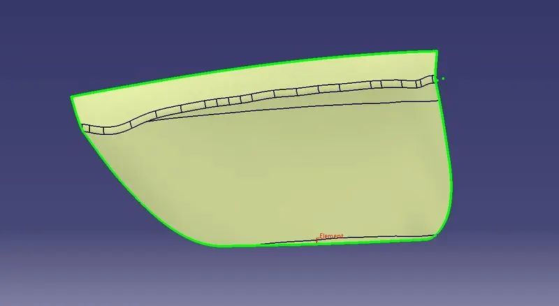
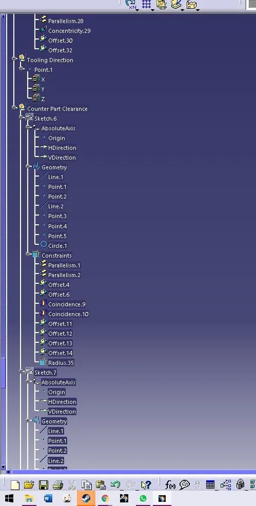
- Tooling Axis: The tooling direction is used to find the direction in which the part is ejected out of the mold. The draft on the part should be positive to manufacture the part easily. The draft angle should be positive concerning the tooling direction.
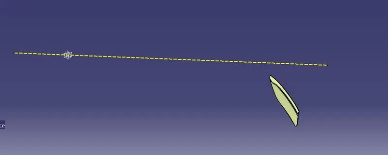
- Class B Surface: The input of the product designer is in the form of the A-class surface. The job of the product designer is to create the B and C surfaces keeping all the aspects for the mold.
Process:
- First, extract all the surfaces for the inclined portion of the base plate.
- Then, offset those surfaces to the value of 2.5mm.
- Extrapolate the surface by some value to get B surface.
- Class C Surface: Class C is where the thickness of the component can be seen.
Process:
- The C class surface will be created using the sweep command and for that, the Boundary lines are obtained from the Class A surface.
- The curve part is then smooth by some value for ease in sweeping.
- Then, all boundary lines are sweep with a draft direction since all the surfaces must have a draft angle of 3 degrees Also, the tooling axis is used as the direction of the sweep.
- Final Joins:
After finishing all the 3 surfaces, join the class A and C surfaces together using the join command. Now, the joined surfaces are then trimmed with a class B surface to form a closed surface.
Now using the close surface command from the part workbench create a solid body.
Also, create the solid surface from the attachment part using the thickness command by 2.5mm.
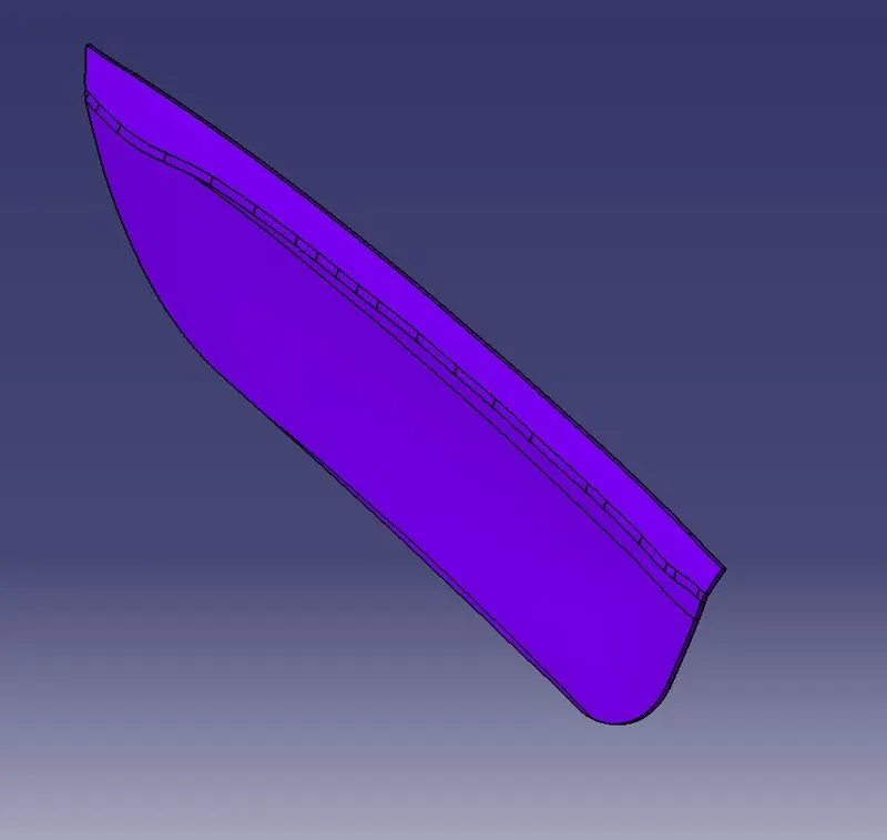
- 2 Way and 4 Way Locators:
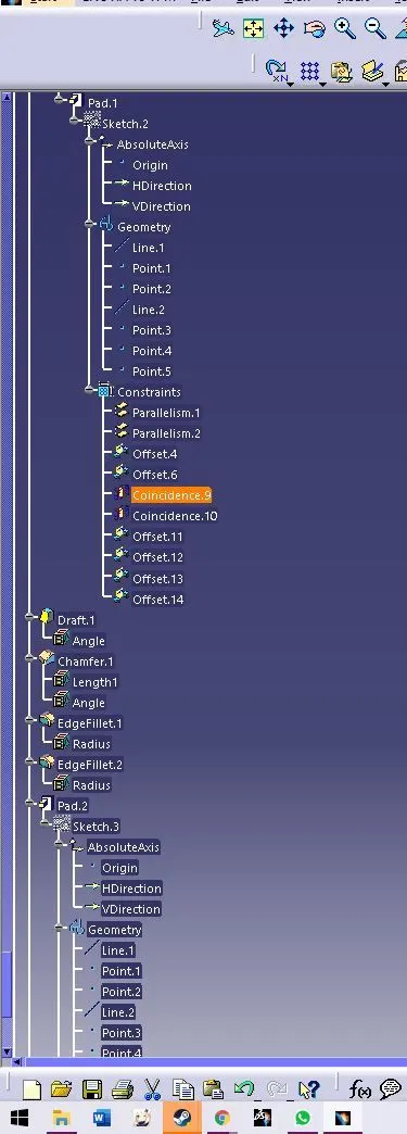
- To create 4-way locators, the ribs should be created intersecting with each other.
- Open the Sketcher Workbench and Draw 2 lines intersecting each other and constraint it.
- Exit the Sketcher Workbench and Pad the sketch with a thickness of 1.2mm.
- Now, provide a draft of 0.5 degrees to the faces. Here the pulling direction is the tooling axis and the neutral face is the top face.
- Provide the chamfer of 3*45 to the edges of the locators.
- For the 2-way locators, only a single line needs to be created and the rest procedure is the same as 4-way locators.

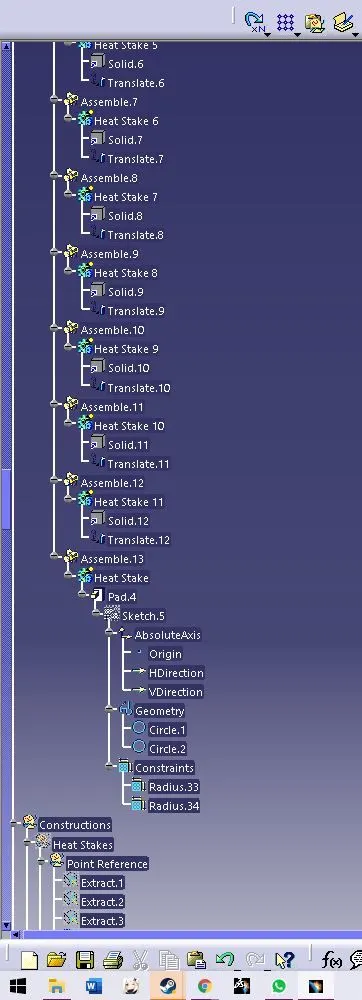
- Heat Stakes:
- To create the heat stakes, open the Sketcher Workbench and Draw 2 circles with diameters of 7 mm and 5 mm.
- Exit the Sketcher Workbench and Pad the Heat Stakes and draft it to 0.5 degrees.
- Draft Analysis
CLASS A Surface
Door Applique
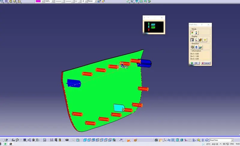
Attachment Surface
- Door Applique Model Views
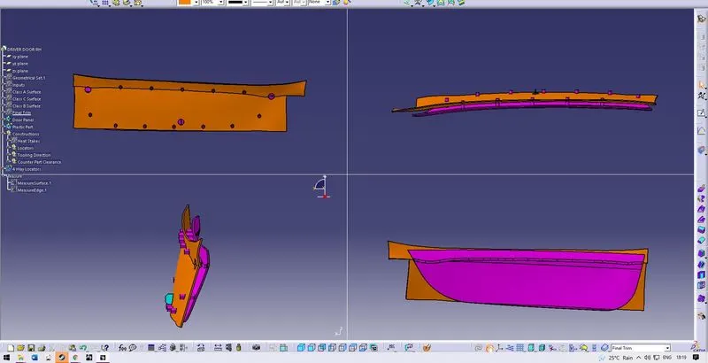
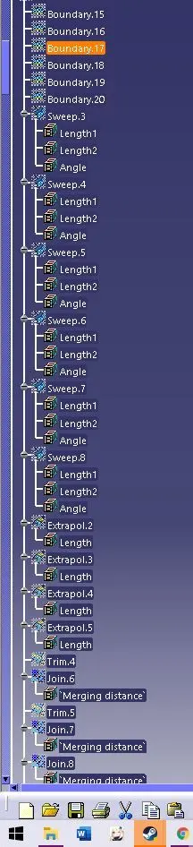
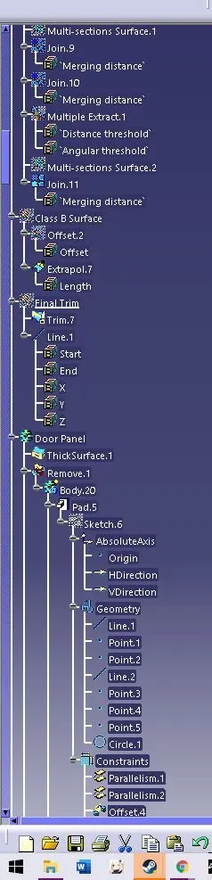
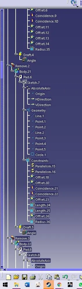
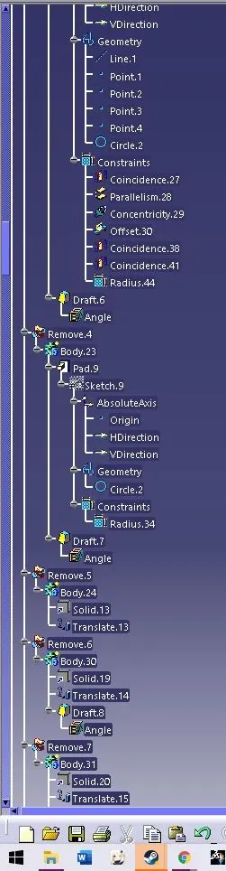
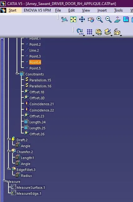
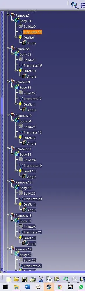
- Tree Structure