Week 9 - Project 1 - Door Applique Design with Engineering Features
Aim:- The Aim of the project is to create a solid model of the given class A surface of the Door Applique and create the Heat Stakes and the locators considering the design rules.
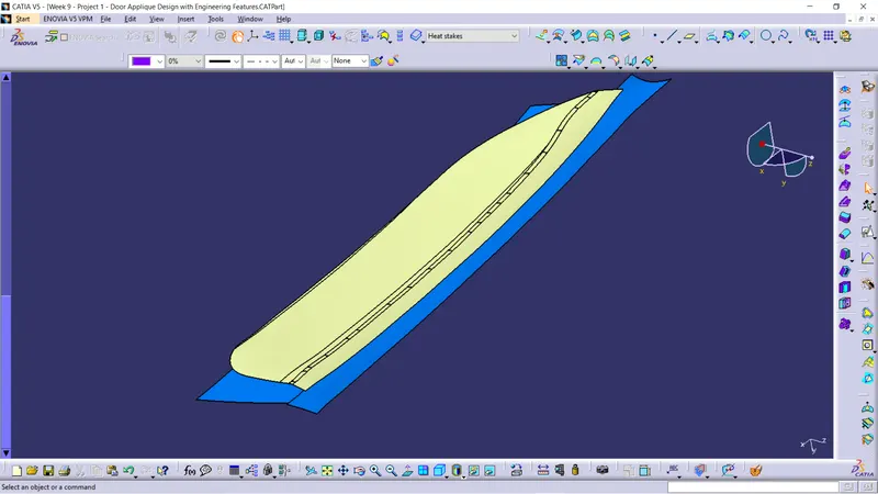
Given Door Applique class A surface.
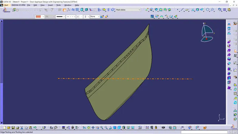
Tooling Axis:-
Here first we will discuss how the tooling axis is created for the give class A surface.
- Here first we just created a point at the center of the surface.
- Next we draw line from the center point along the y direction.
- The line drawn is the TOOLING AXIS of the class A surface
Draft Analysis along the Tooling Axis :-
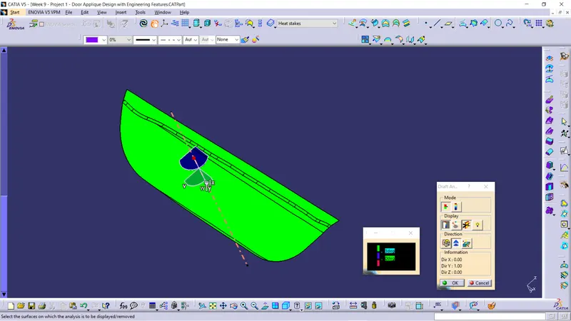
- Draft analysis was performend on the class A surface along the tooling axis to analyse if the given component is toolabe along the tooling dircetion.
- Feature draft analysis option is used to perform the draft analysis on the surface.
- Compass is placed on the created tooling axis using the option in draft analysis ,next the surface is chosen to perform the draft analysis.
- We take maximum of 3 degree of draft angle for the surface.
B Surface creation :-
In creation of B surface we divide the class A surface in different geometrical parts and at last we trim and join all together and made in B surface.
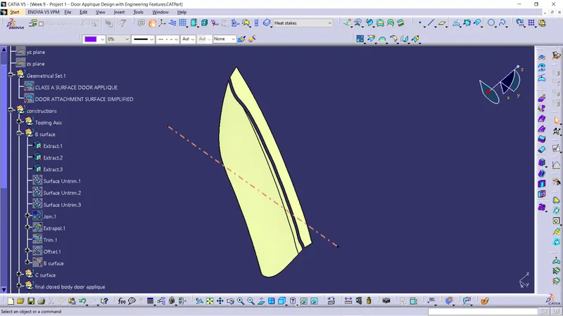
First we extracted the surfaces of class A.
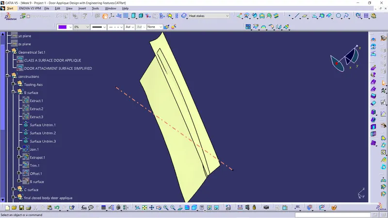
Next we untrimmed the extracted surfaces.
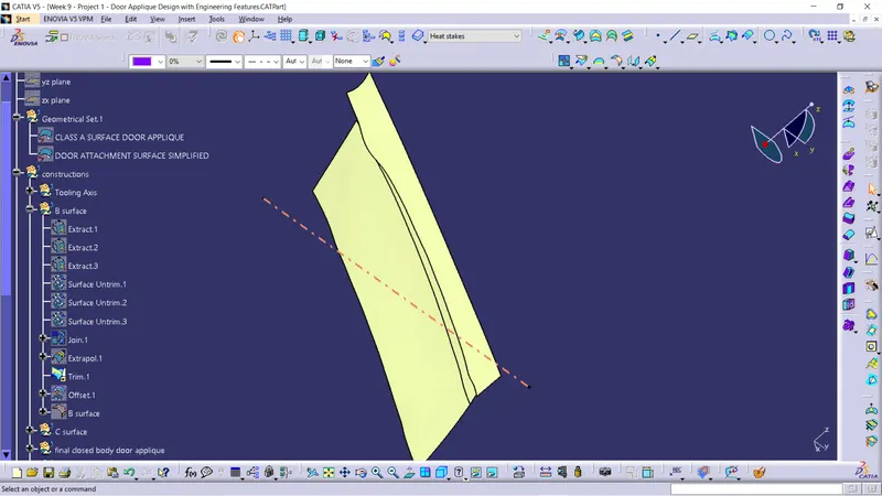
Next we joined and extrapoled and trimmed the surface.
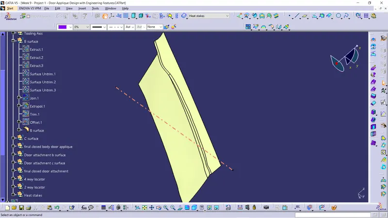
This is the final class B surface.
C Surface creation :-
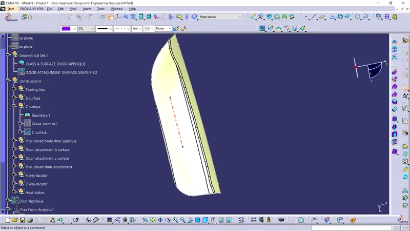
Here we kept the boundary for the class A surface and we smooth the surface.
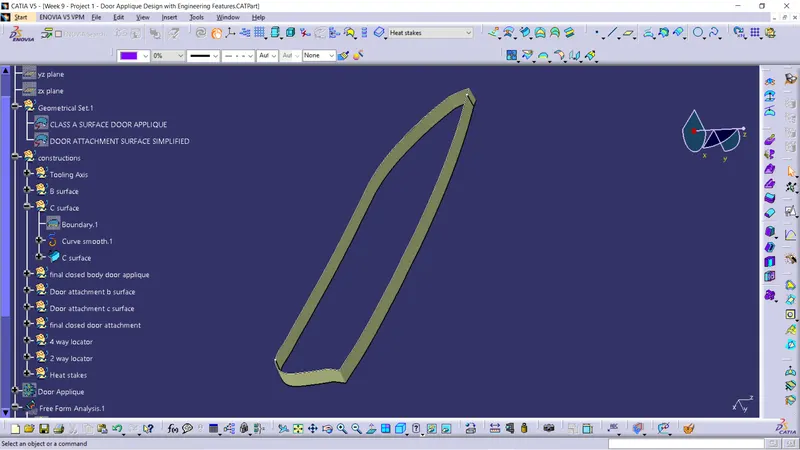
Next we sweep the smooth line along the draft direction at 3 degree angle. This is the final class c surface.
Final closed surface:-
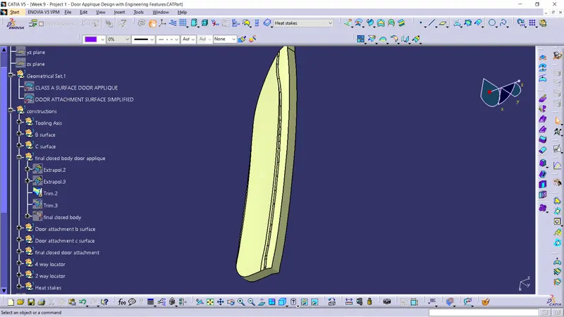
First we join the class A and class C surface.
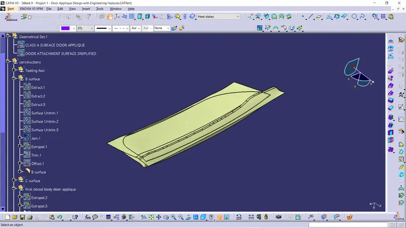
Next we trim the joined surface with class B surface.
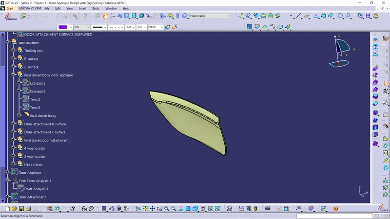
And we get final closed surface.
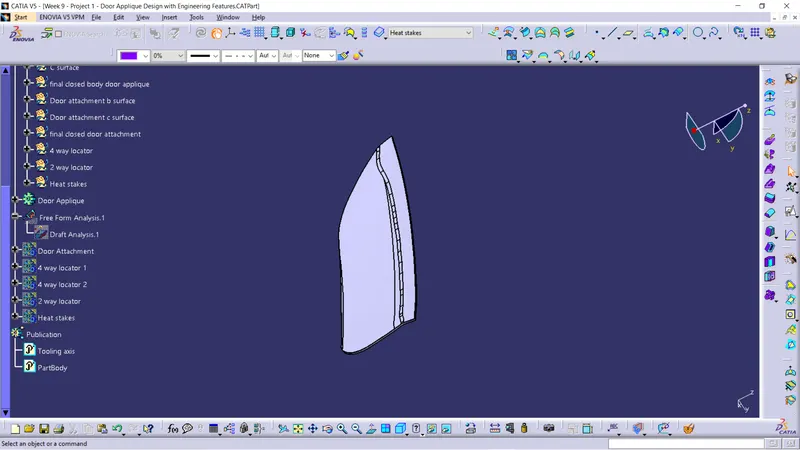
This is the final closed solid body of the door applique.
Locator creation :-
Locators are used to arrest its degree of freedom using 3-2-1 principle for a component.The locators are arranged at B side surface of the component.
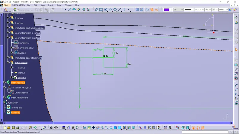
First we selected a plain and drawn the sketch.For creating a locator we use rib design rules.
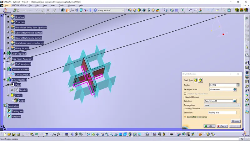
After pad the ribs we draft along the tooling axis at 0.5 degree.
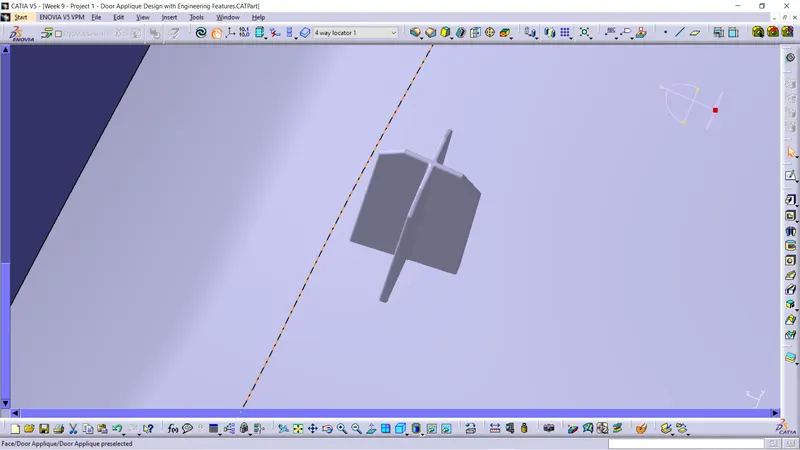
This is the final output of 4 way locator.
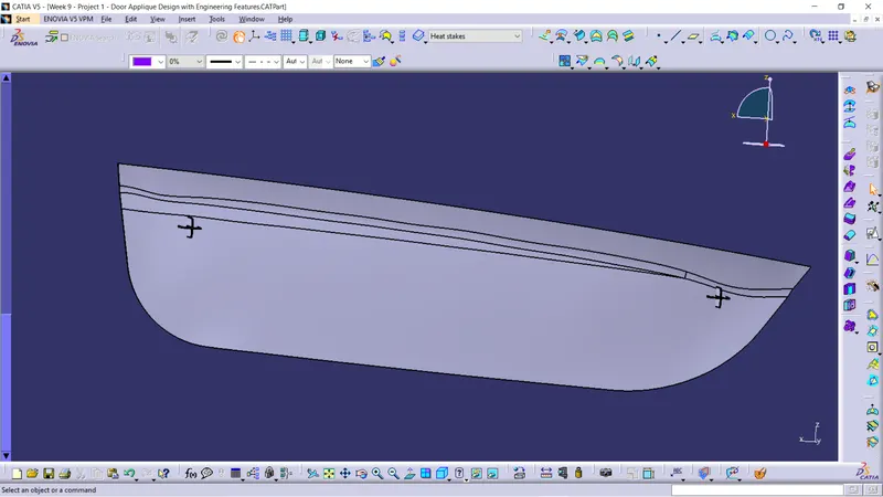
Next we translate the 4 way locator to next end of the surface.
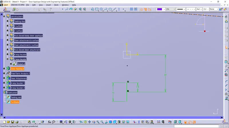
As the same way we created the 4 way locator we create 2 way locator.
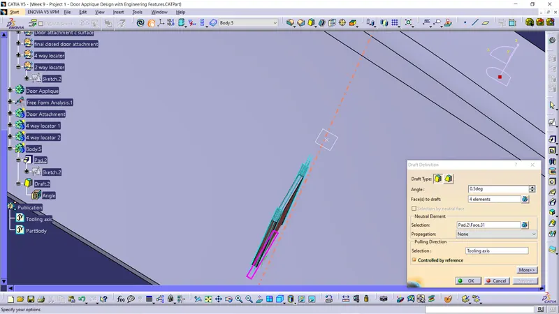
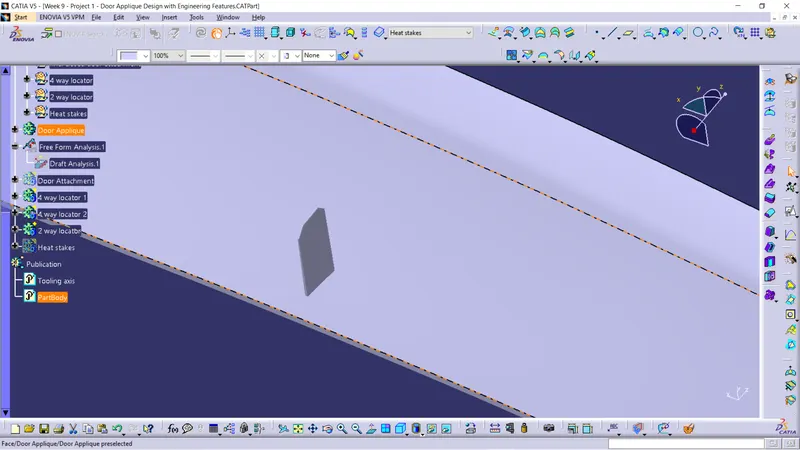
This is the final 2 way locator.
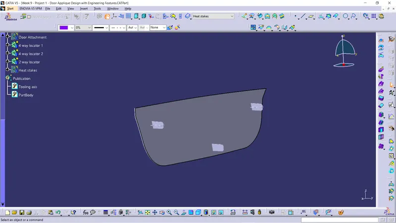
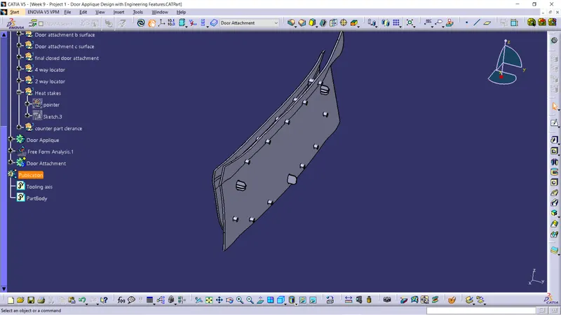
Door Applique with 4 way and 2 way locator.
Creation of Heat Stakes :-
Heat staking also known as thermoplastic staking is the process of joining two dissimilar materials together. In heat staking we use local heating and cooling to raise the temperature of plastic components and allow plastic reforming to be carried out.
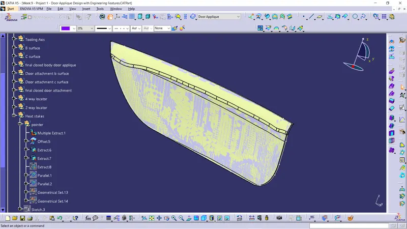
First we extracted the class A surface.
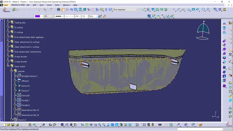
Next we offset the surface and extracted the boundray lines.
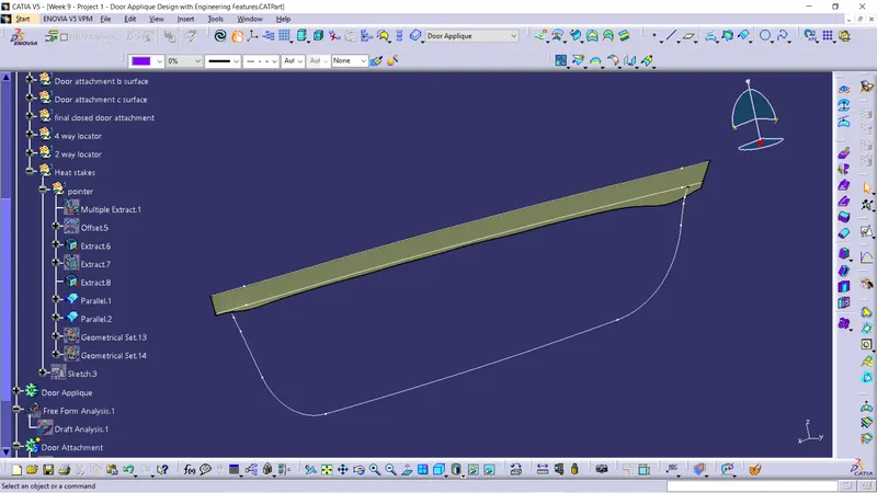
Next we parallel curve the lines.
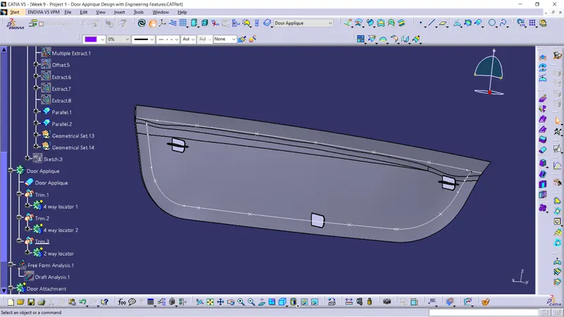
And next we add points on the lines.
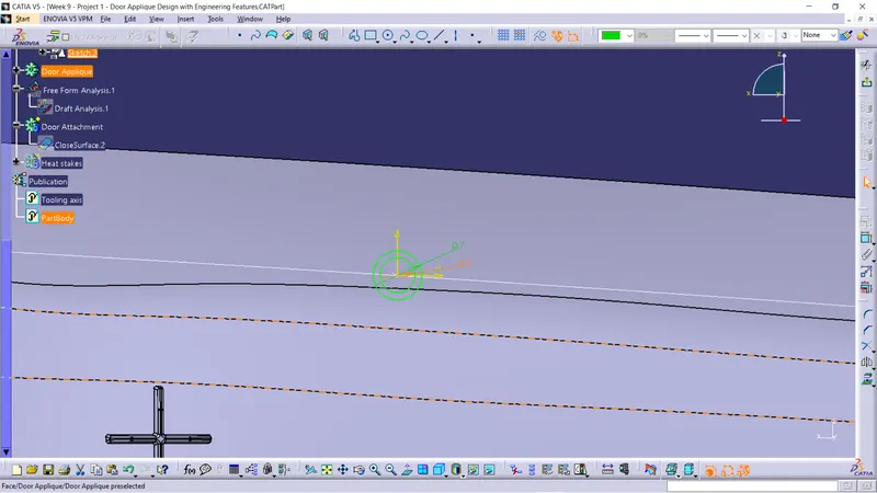
Next we draw sketch for the points to create the heat steaks.
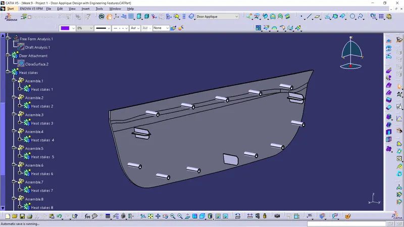
Next we pad the heat steak and translate the heat steak for all the points.
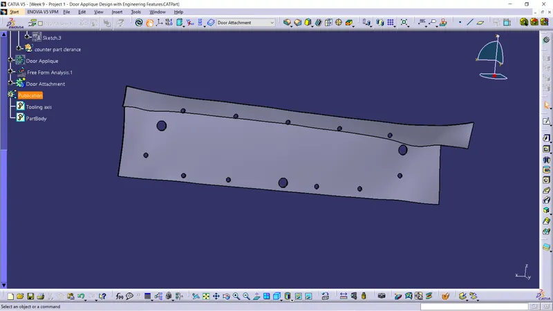
Here we pad the sketch and remove from thr door attachment using boolen operation.
Draft analysis on final body :-
- Draft analysis was performend on the solid enclosed body along the tooling axis to analyse if the given component is toolabe along the tooling direction.
- Feature draft analysis option is used to perform the draft analysis on the solid enclosed body.
- Compass is placed on the created tooling axis using the option in draft analysis ,next the solid enclosed body is chosen to perform the draft analysis.
- We take maximum of 3 degree of draft angle for the surface.
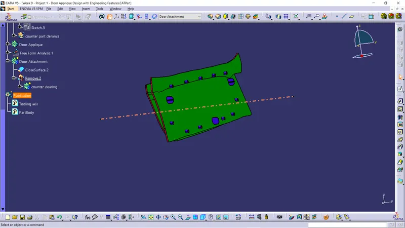
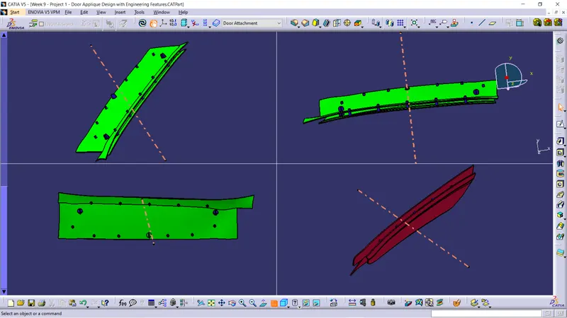
Different views of door applique when draft analysis is performed along tooling axis.