Week 9 - Project 1 - Door Applique Design with Engineering Features
Project 1 - Door Applique Design with Engineering Features
OBJECTIVE - This project intends to
- Create a tooling axis for the given Class-A surface and make an initial draft analysis
- Create Class B and C surface from the given class A surface
- Create a door applique plastic component using Class A, B, and C surfaces
- Perform a draft analysis for the solid component using the tooling direction
- Create the Heat Stakes and the locators considering the design rules
Introduction
In this report, door applique, which is an automotive plastic component modeled following the OEM standards. A detailed explanation of component modeling, draft analysis, and creation of engineering features are illustrated. For the component design CAD tool, Catia V5 is used.
The procedure followed in creating the plastic component
- In the first step, the tooling direction is identified and a tooling axis is created
- Step two initial draft analysis for the given class A surface
- Step three creating a B Surface
- Step four creation of C surface
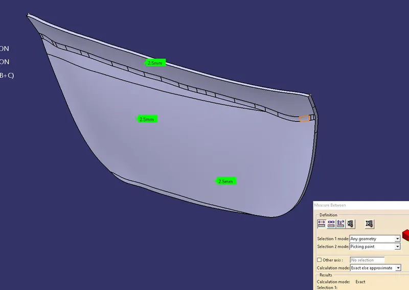
- In step five all the surfaces are joined together and a solid model is generated
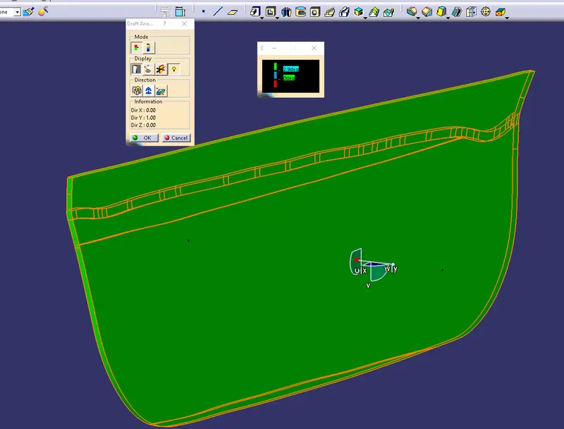
- Again a draft analysis is made on the solid component in the sixth step
- The engineering features are created on the B surface in the seventh step
- Final draft analysis is performed in the eight-step
These are the main steps that are followed here to accomplish the given project.
TOOLING AXIS
The tooling axis is the direction in which the mold or core and cavity get opened and the component is ejected. Clearance of the component is checked using this tooling axis. This means all the faces of the component when ejected along the tooling axis, must come out of the mold easily, without failing.
DRAFT ANALYSIS
The draft is the angel
The analysis is the detailed examination of the part.
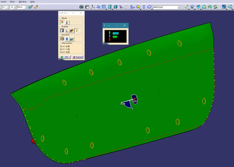
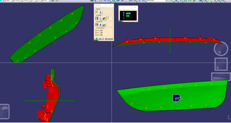
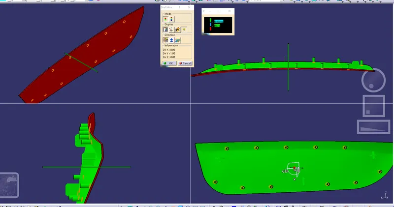
Draft analysis is the angel examination on all the surfaces of a component. The angle on the surfaces is examined along the tooling direction. The minimum draft angle is 0.5°. However, up to 3° is widely accepted. To know whether all the surfaces have that minimum draft or not, this analysis is made. Giving some draft to the part surfaces makes it easier while ejecting. Generally, drafts are given in the direction of mold movement. Draft analysis ensures whether the designed part can be easily ejected from the mold properly (without causing friction between the solid part and core, cavity).
Automotive trim parts have mainly three surfaces A, B, and C.
A SURFACE
A surface is a visible surface that has some aesthetic properties. These surfaces are designed by the designer using the software Alias and give the surface to the product designer to model the complete product.
B SURFACE
B surface is the inner surface of the component, which also has engineering features. This surface is developed by the product designer and gives to manufacturing.
C SURFACE
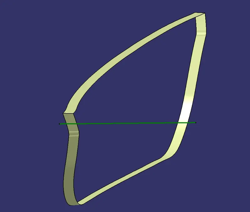
C surface is used to join the A and B surfaces. This surface is created along the tooling axis with a required draft on it.
ENGINEERING FEATURES
There are different types of engineering features used in plastic component design. Each type of engineering feature has an individual purpose. And each of them is designed following some individual design rules. However, in this project, two engineering features namely Locator pins and heat stakes are used in the component design.
HEAT STAKES
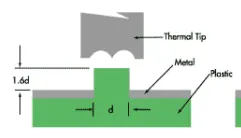
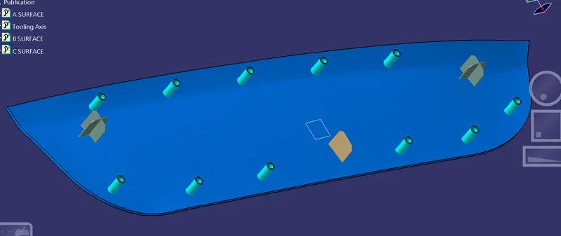
- Heat stakes are used to weld two or more plastic components or dissimilar materials. In other words, it is also known as thermoplastic staking.
- Heat stakes are the vertical cylindrical structures added to the class B surface
- To form an assembly, a plastic stud or boss is given to the child component and a hole for the parent component.
- The boss on the child component is melted then the molten material forms on the parent component. Later the material gets cooled and forms an assembly.
In the below-displayed picture in the place of the metal component, it can also be a parent plastic component.
ADVANTAGES
- No need of going for secondary operations like screwing the components
- Simplification of machinery
- Reduce the cost of machinery
- Multiple fastening points
DISADVANTAGES
- Once the assembly is done the components cannot be separated without damaging them
LOCATOR PINS
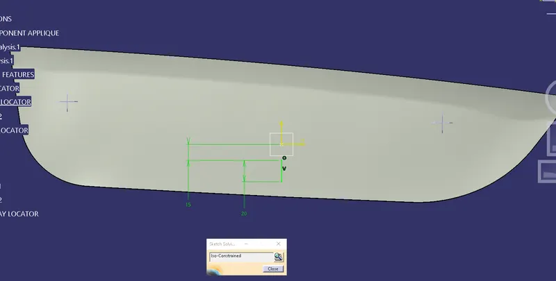
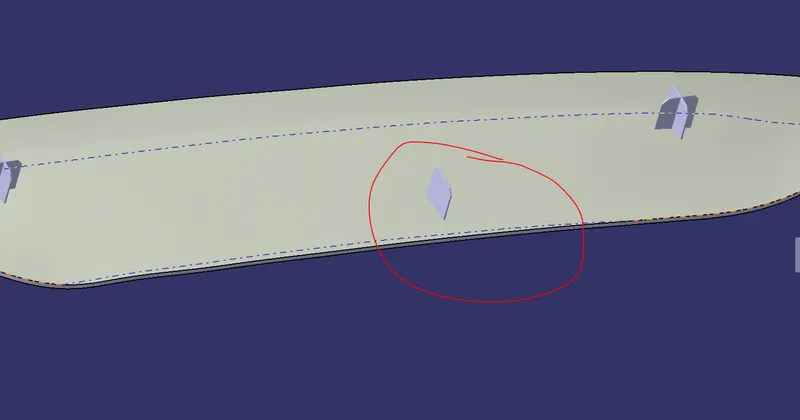
- The purpose of locator pins is to arrest the degrees of freedom of a component.
- They are classified into two types i.e. four-way locator, 2-way locator, and are rib-like structures
- Here following a 3-2-1 design principle the locator pins are created
- The 3-2-1 principle of location is used to constrain the movement of the workpiece along the three axes XX, YY, and ZZ. This is achieved by providing six locating points, 3 pins in the base plate, 2 pins in the vertical plane, and 1 pin in a plane that is perpendicular to the first two planes
GIVEN INPUTS
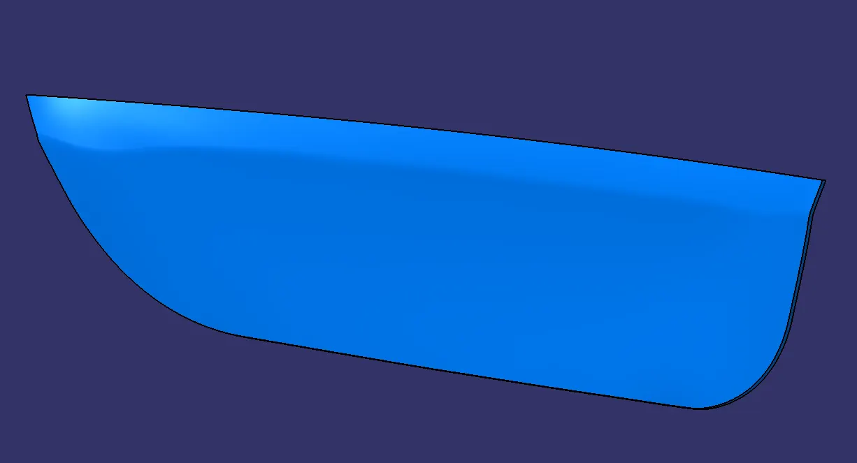
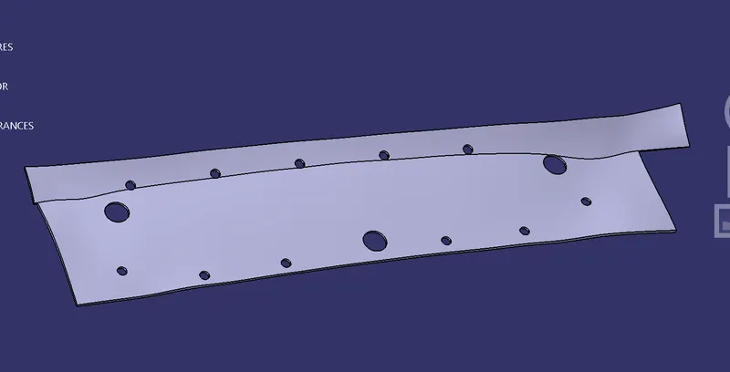
The given input is the A surface which is an automotive trim component 'Applique'
STEP 1 CREATION OF TOOLING AXIS
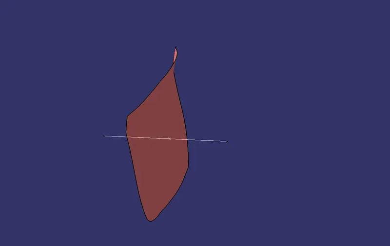
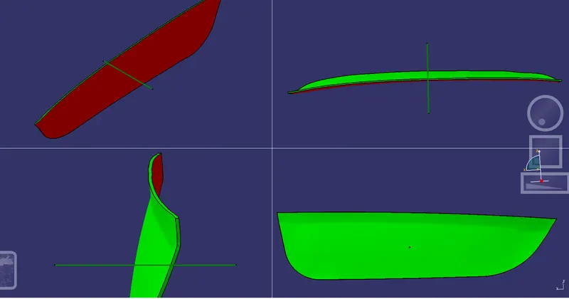
For this component, the tooling axis is taken in the Y-direction. Because all the surfaces in the component are perpendicular to that direction.
STEP 2 PERFORMING DRAFT ANALYSIS ON GIVEN CLASS A
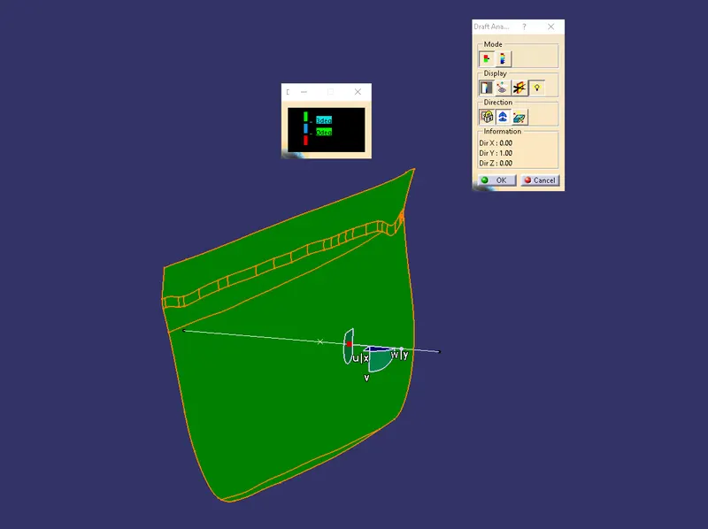
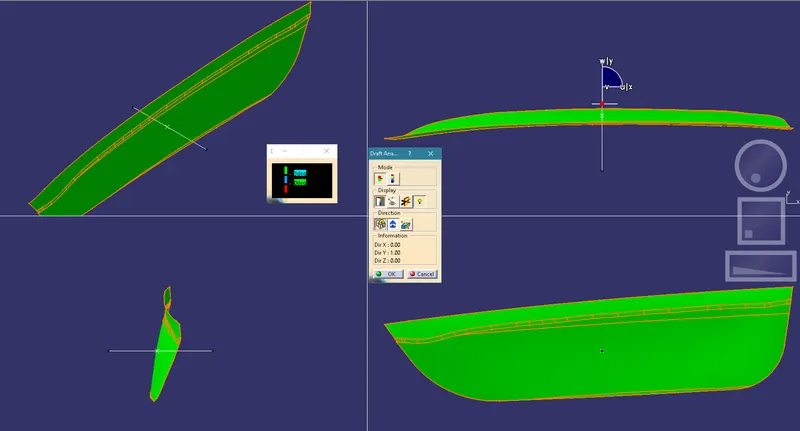
Initial draft analysis is performed for the given class A. The DA is performed along the created tooling direction
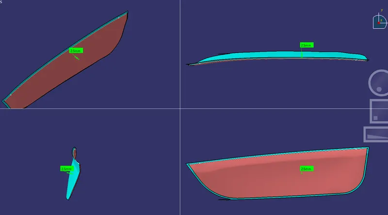
STEP 3 B SURFACE
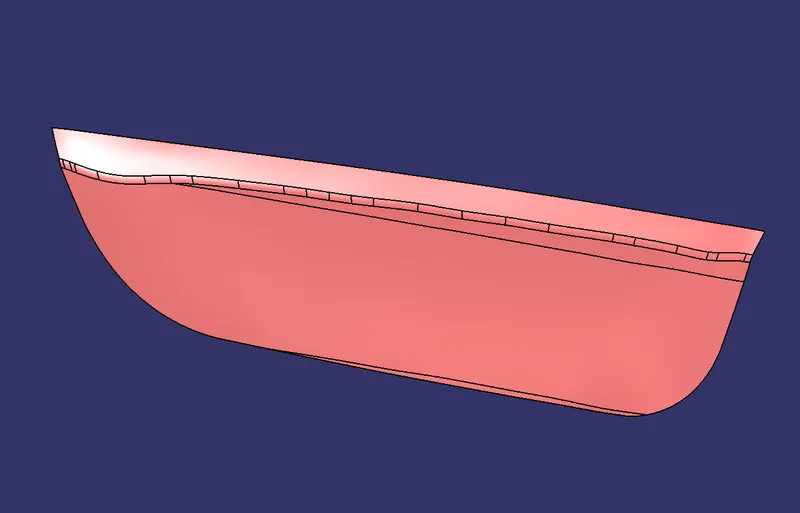
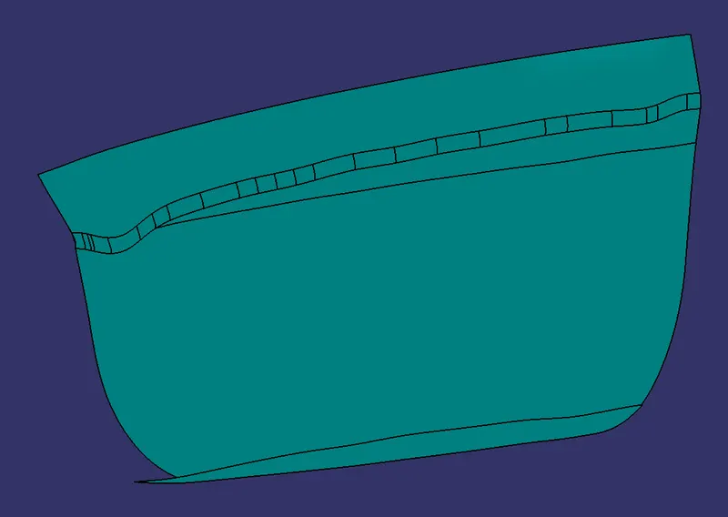
Taking class A surface reference the surface B is created. B surface is created by having an offset of 2.5mm away from surface B.
STEP 4 C SURFACE
To join surfaces A and B the surface C is created by giving a draft angle of 3 degrees along the tooling axis
STEP 5 CREATING A SOLID BODY
STEP 6 DRAFT ANALYSIS ON SOLID BODY
STEP 7 CREATING ENGINEERING FEATURES ON B SURFACE
LOCATOR PINS
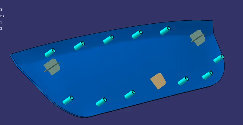
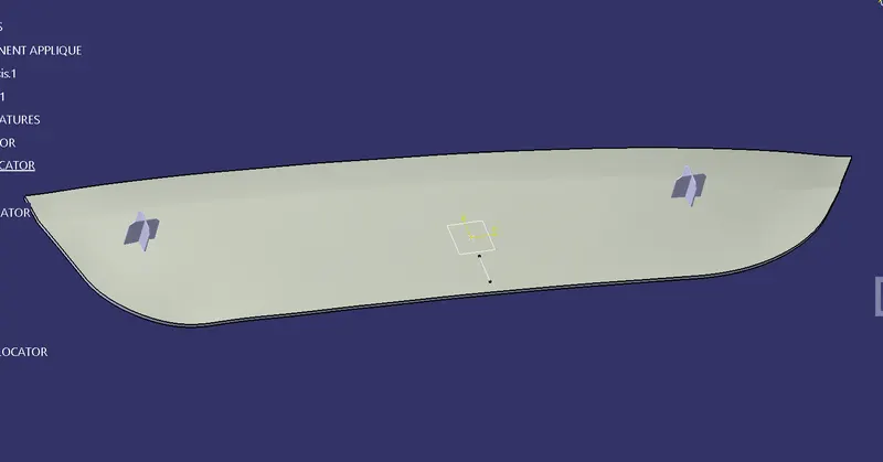
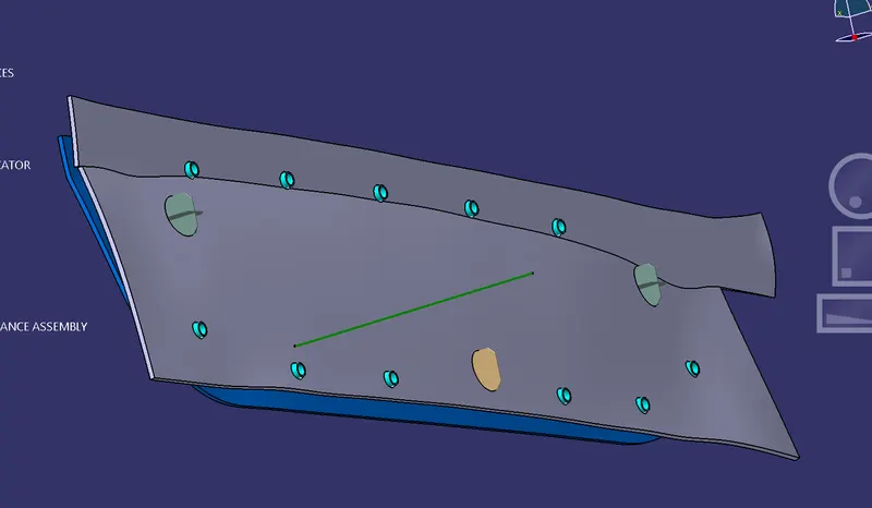
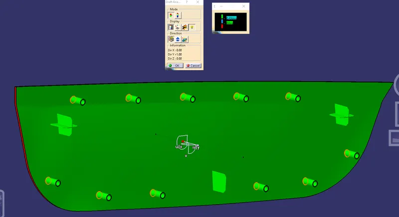
In general, these pins also look like ribs. The design rules followed while creating Ribs are followed here to create these pins. Here 2 four-way locators and 1 two-way locator pins are used to arresting the 10 degrees of freedom of the component. Positive and negative translation along X, and Z direction, rotation along X, Y, and Z-axis. To furtherly arrest one DOF along Y direction, heat steaks are created.
Following are the design rules involved in creating Ribs/Locator pins on the B surface
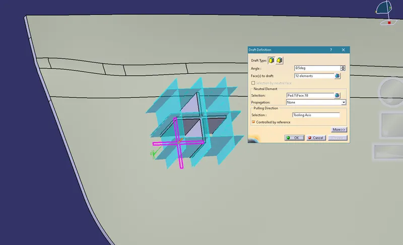
- Draft - We know the draft angle of 3° is ideal for any surfaces in the plastic component. But for the ribs, 0.5° per side is the minimum.
- Wall thickness of the ribs - The wall thickness of the ribs can be 0.4 * wall thickness of the component. If t is the wall thickness of the component, then the wall thickness of the rib is 0.4*t
- Minimum wall thickness at Rib tip - The tip of the rib should maintain a minimum wall thickness of 0.75mm. Less than that is not advisable. Because after changing the flow direction of the molten material, it is not easier to reach the very thin area. For ribs, it takes a 90° deviation from the main flow direction.
- Rib fillet radius (r) - Optimal rib fillet radius is 0.25mm. But if the component is thicker, we can go until 0.5mm. Above that is not advisable.
- Rib Depth/Height - Rib height must be 5*the component wall thickness
- Spacing b/w ribs - Ribs should be spaced at the H/W ratio when more than one is there. where H is the height of the rib and W is the width b/w ribs. And the accepted ratio is 3:1
- Rib root thickness - The root thickness should not exceed 30% of the component wall thickness
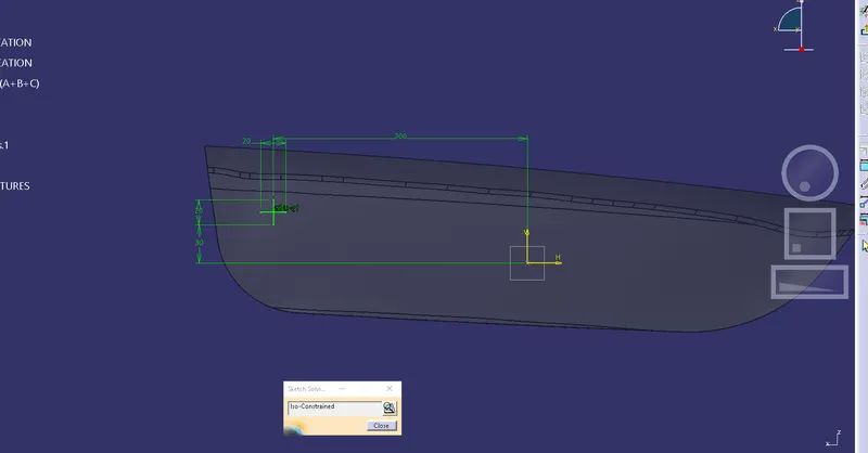
4 WAY LOCATOR
A draft angle of 0.5 degrees is given
Two four-way locators are created on the B surface
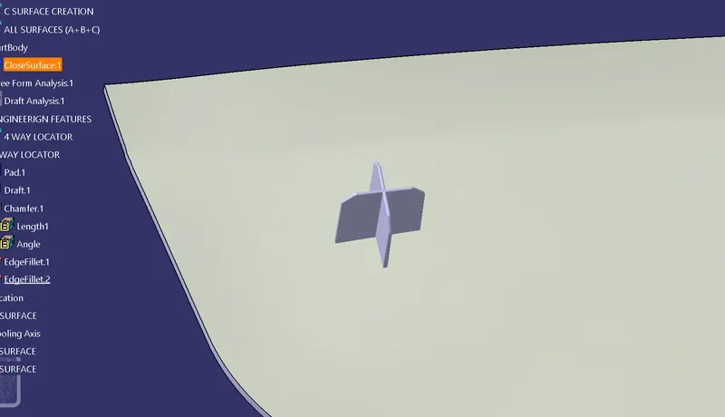
TWO WAY LOCATOR

HEAT STAKER
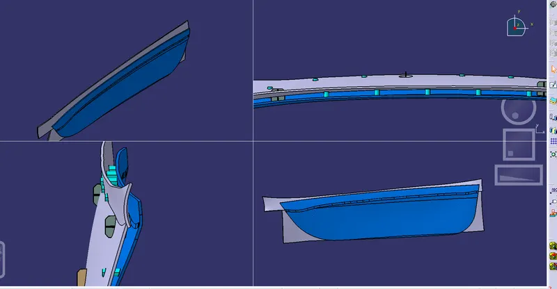
COUNTERPART CLEARANCES
FINAL DRAFT ANALYSIS ON THE COMPLETE MODEL
B SURFACE SIDE
CONCLUSION
The modeling of the door applique component is accomplished by considering all the requirements