Week 9 - Project 1 - Door Applique Design with Engineering Features
Objective: To create class B & C surface along with the tooling axis and also to perform draft analysis for the given class A surface and final component which consists of both B & C surfaces and heat stakes & locators with the given design considerations using Catia V5R21.
Procedure:
1. Enter into generative shape design workbench and insert a geometrical set and name it as tooling axis.
2. To create tooling axis, create a point on the class A surface and use line command and select point-direction to create a line.
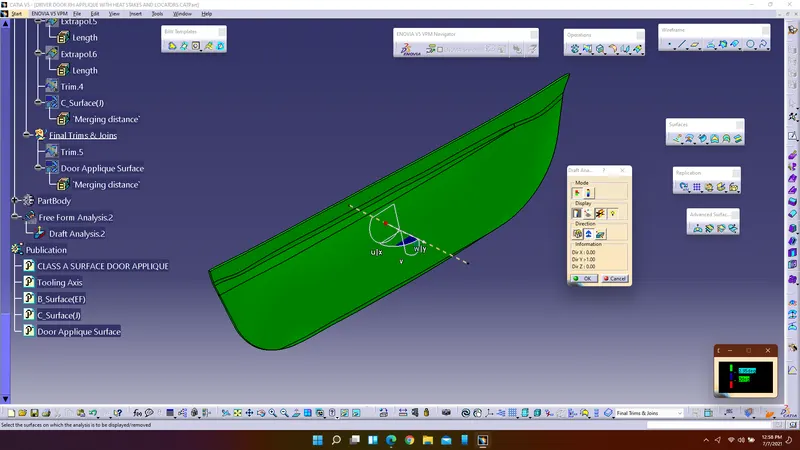
3. Publish the tooling axis for quick reference and perform draft analysis on the class A surface.
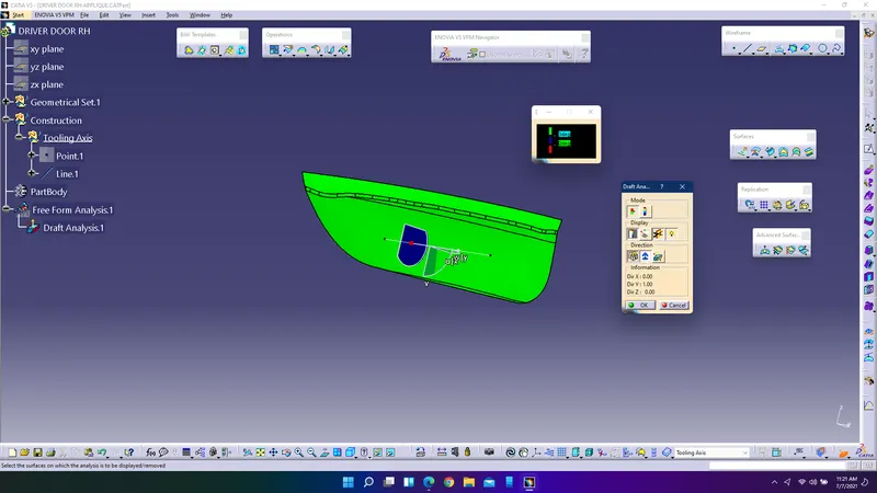
4. To create class B surface, extract the class A surface, untrim it and extrapolte it and use trim command to get the exact profile.
5. Create fillet using edge fillet command and create C surface by extracting the edges of class A surface.
6. Using Sweep and multisection surfaces commands create class C surface and join all the class C surfaces.
7. Trim the class C with class B surface and obtain the exact geometry required.
8. Join the trim which is obtained from above step with class A surface and make sure to check the boundary, if the boundary is not appeared then the surface is fully closed and ready to use the close surfaces by entering into part design workbench and convert the surfaces into solids.
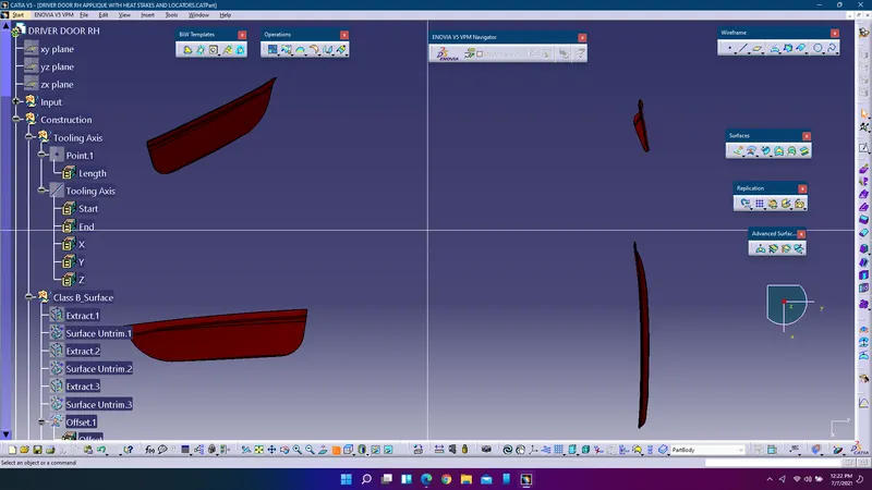
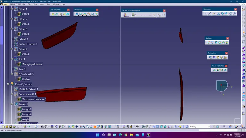
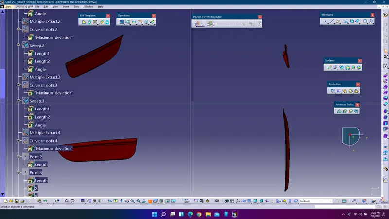
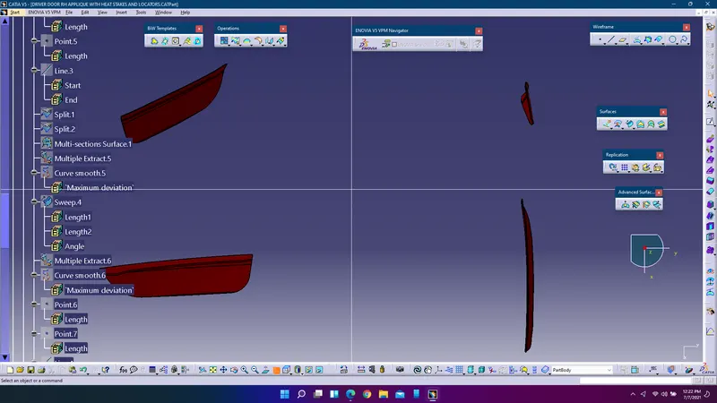
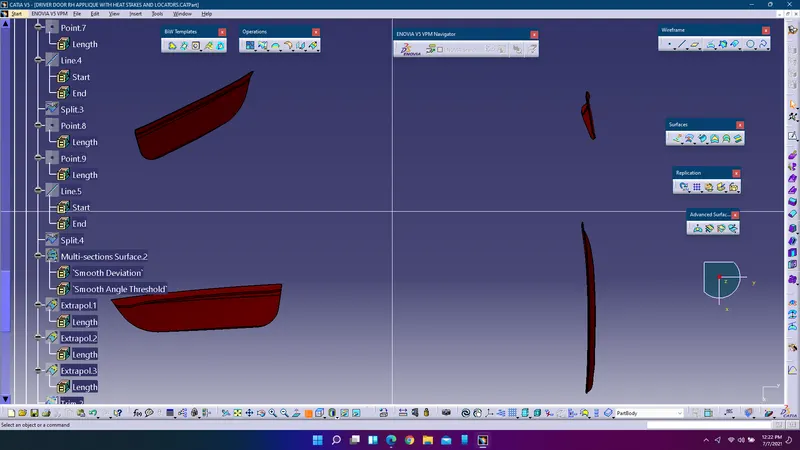
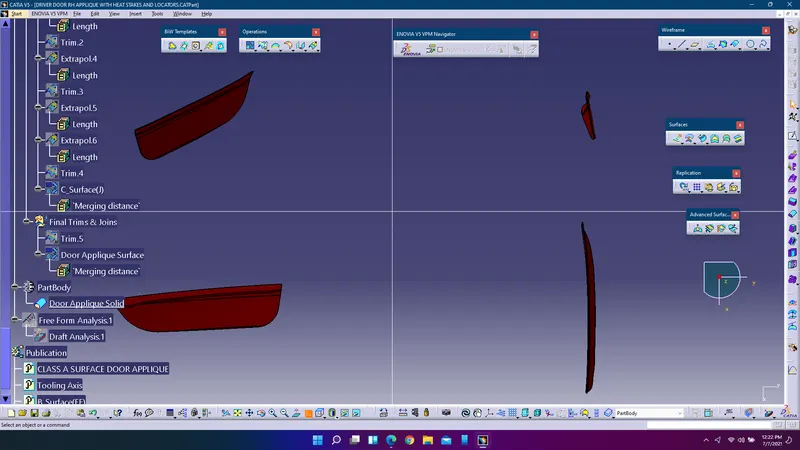
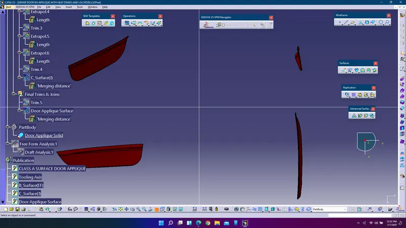
9. Perform the draft analysis for the final part body.
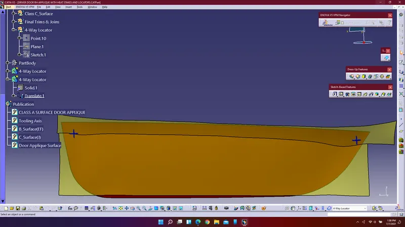
10. Create the 4-way locator on B-surface of the part body by creating a sketch and make sure it is iso-constrained.
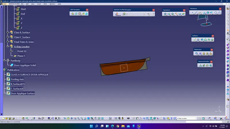
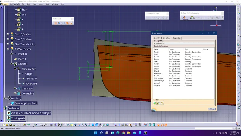
11. Enter into part design work bench and insert body naming it as 4-way locator and using pad command thicken the sketch.
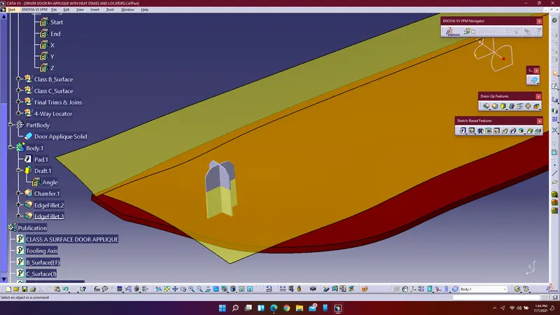
12. Provide draft angle to the locator and also chamfer and fillets. Copy the 4-way locator and paste in the same part and translate it to place anywhere.
13. Union trim the locator with the partbody.
14. Similarly create the 2-way locator on the B-surface, follow the same procedure such as extruding it by inserting a new body and drafting it along the tooling axis direction and union trimming it with the part body.
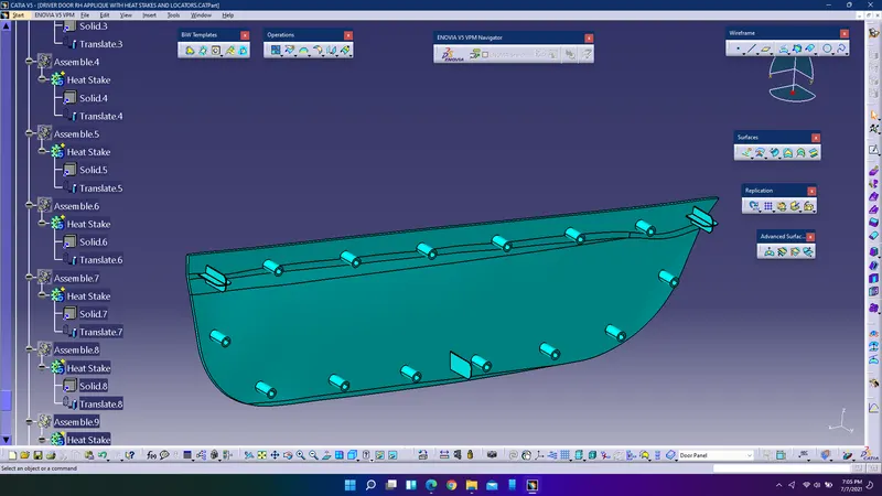
15. Create the heat stakes by extracting the A-surface and by offsetting it to 2.5mm. Extract the boundaries and offset them on the surface using parallel curve command.
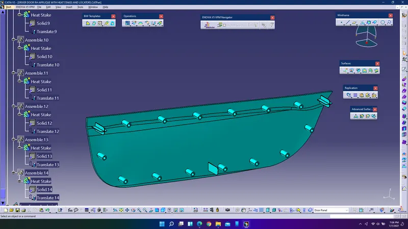
16. Create points on the curve to locate the heat stakes. Sketch the heat stakes and enter into the part design to extrude them by inserting a body and draft the heat stake using draft command. Copy the heat stake which is created and paste it special as a result so if any changes made to the parent stake will effect on the children stakes.
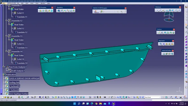
17. Translate them and create the stakes on the points and using assemble boolean command assemble them with newly inserted body and rename it as heat stakes assembly.
18. Union trim the heat stakes with the partbody and provide clearance for both heat stakes and locators by creating sketches.
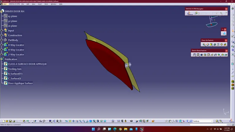
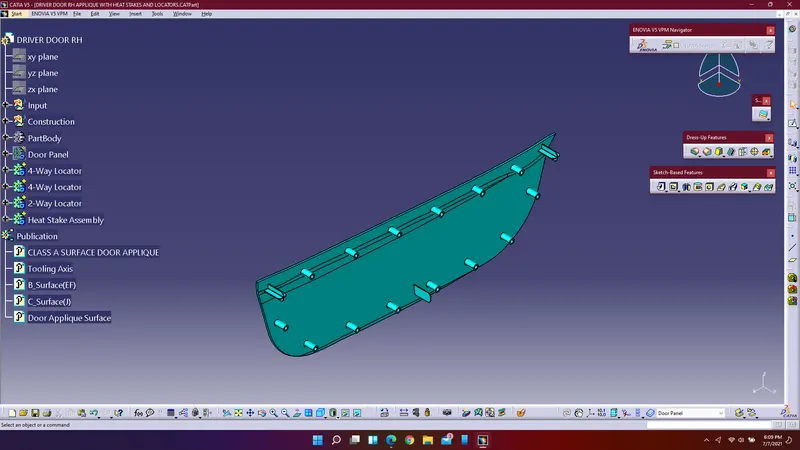
19. Remove the clerances with the door panel and save the file.
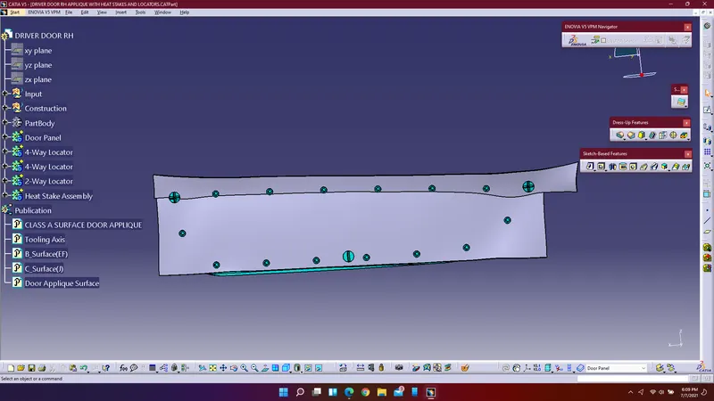
20. Perform draft analysis for the whole component.
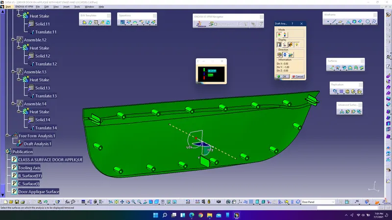
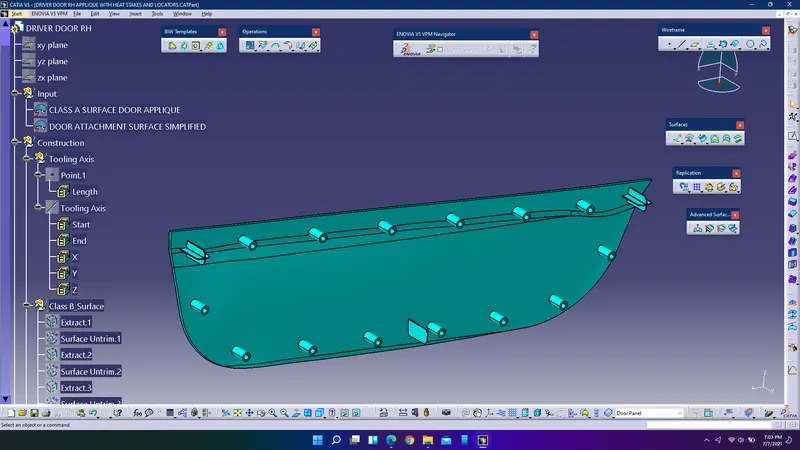
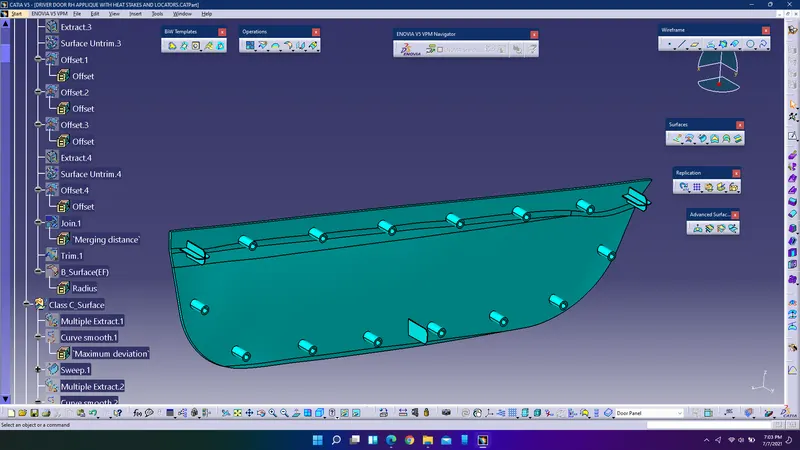
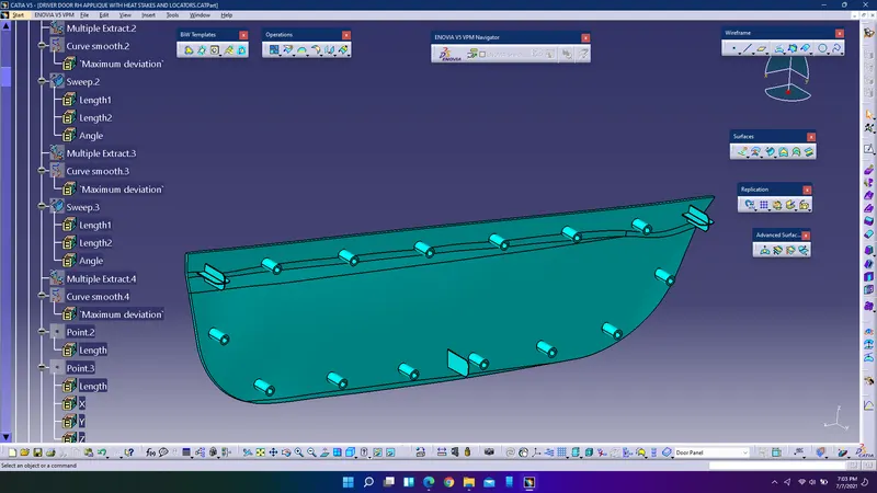
Feature Tree Diagram:
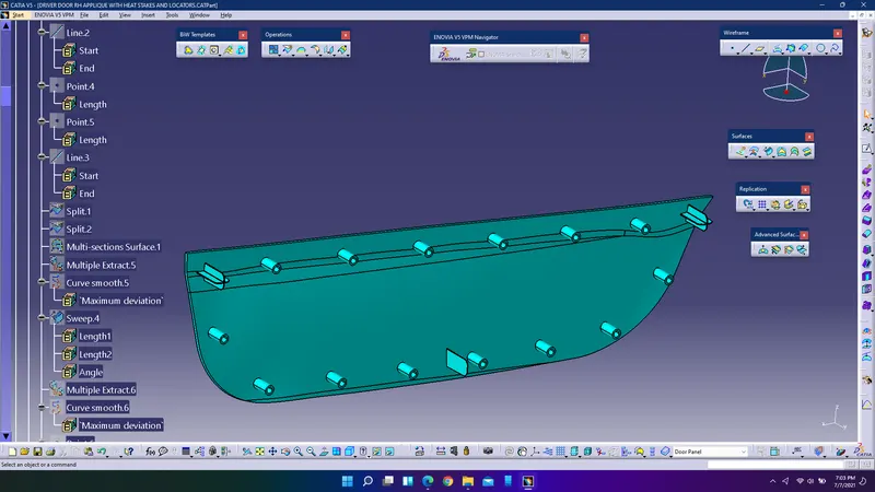
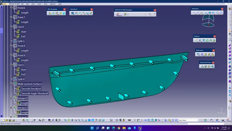
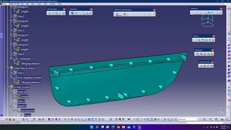
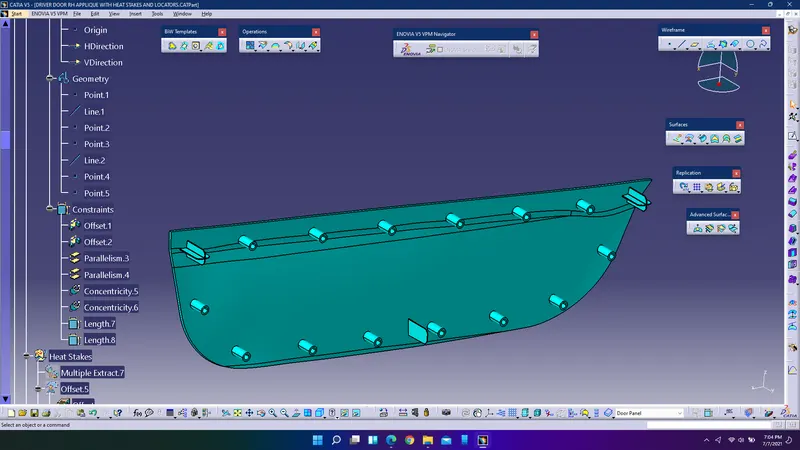
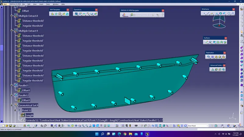
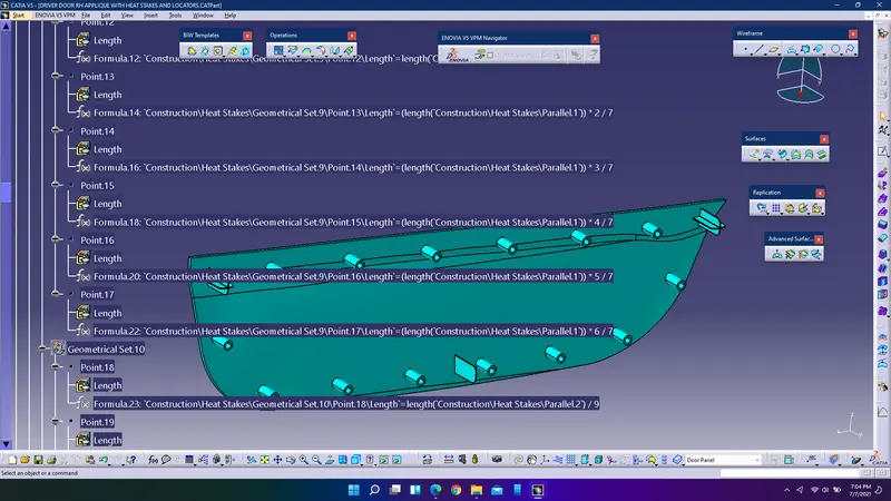
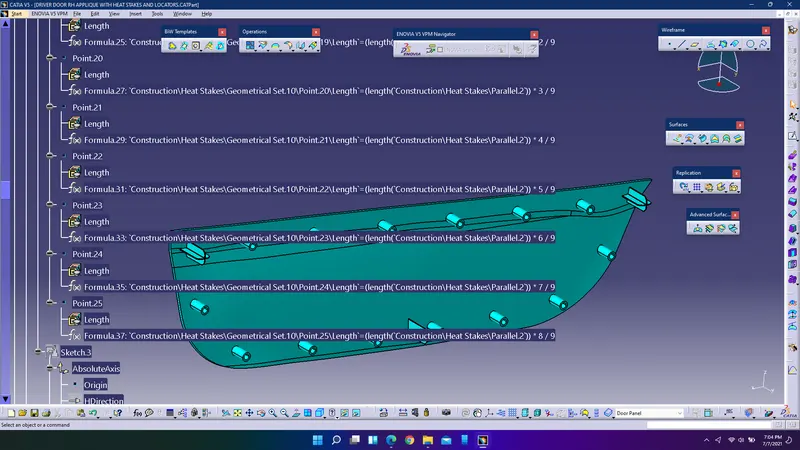
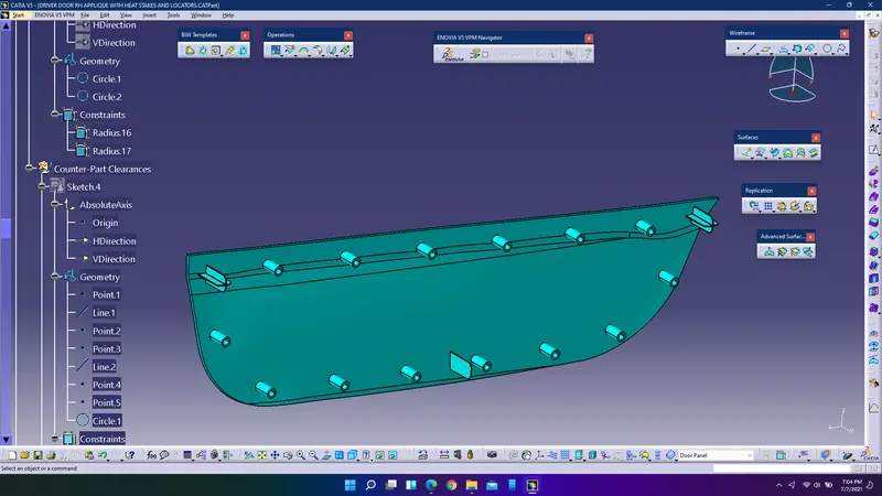
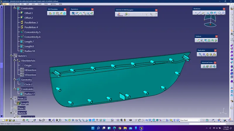
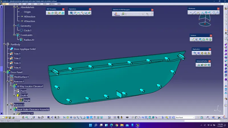
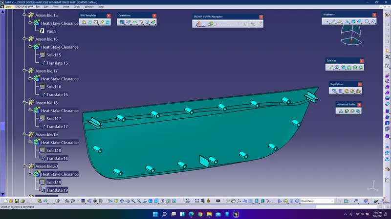
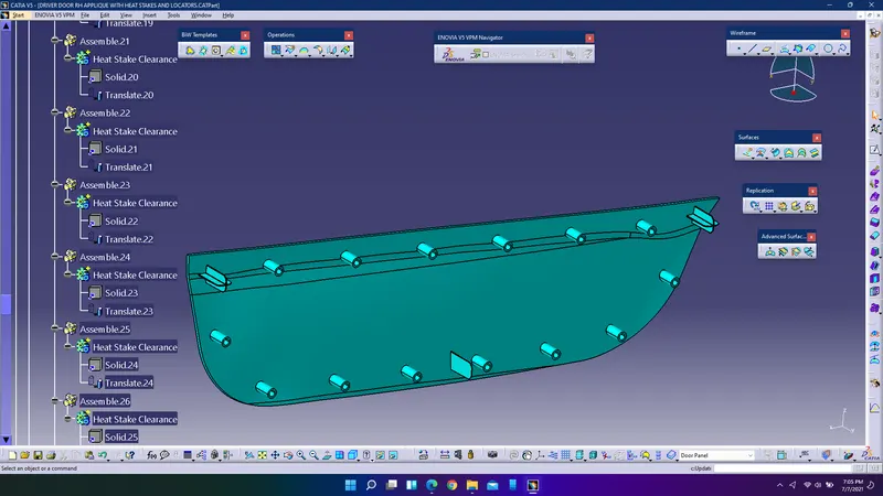
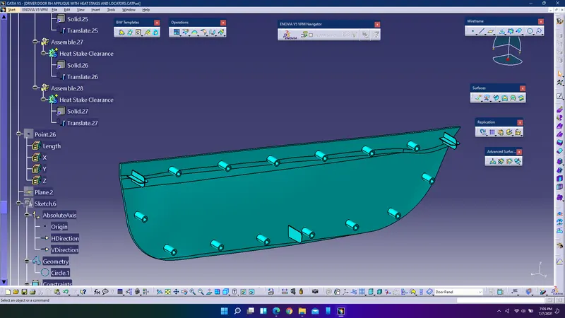
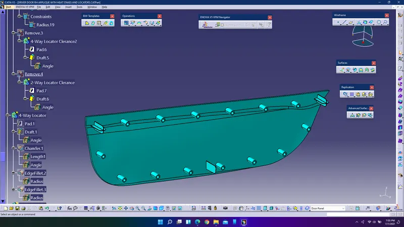
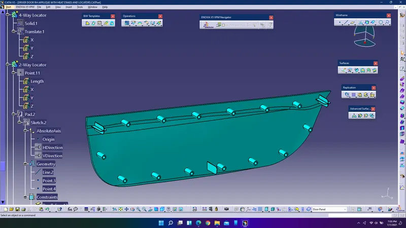
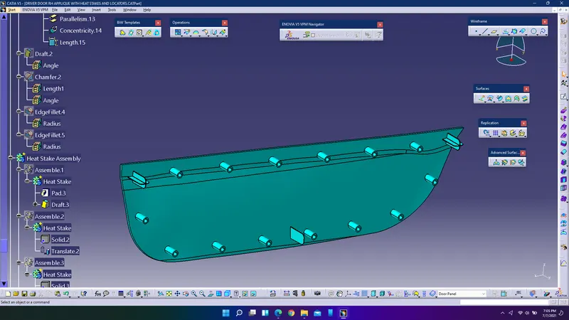
Conclusion:
Both class B & C surfaces were created with given considerations and performed draft analysis for both class A,B,C surfaces and the final component using Catia V5R21 and also provided heat stakes and 4-way & 2-way locators on the engineering surface.