Week 9 - Project 1 - Door Applique Design with Engineering Features
AIM :
- To Create the Base Bracket Plastic component through the given Class-A surface. To begin with, the tooling axis for the given Class-A Surface should be created meeting the requirements of the draft angle and at the end perform the Draft analysis on the model.
- Create the Heat Stakes and the locators considering the design rules mentioned in the video for the door applique.
THEORY :
- Heat stakes
In manufacturing products with thermoplastic components, it is often necessary to join a thermoplastic to a part of dissimilar material, whether it be metal, a dissimilar plastic, or other material. This technical information sheet provides design guidelines, configurations, and techniques for successful thermal (heat) staking.
GENERAL DESCRIPTION:
Thermal staking is an assembly method that uses the controlled melting and reforming of a
plastic stud or boss to capture or lock another plastic or metal component of an assembly in place.
The plastic stud protrudes through a hole in the component to be locked in place. The heated thermal tip contacts the top of the stud, which melts and fills the volume of the tip cavity to produce a head, locking the component in place.
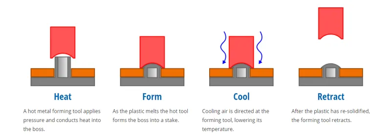
The progressive melting of plastic under continuous pressure forms the head.When staking, the right combination of heat and pressure for the application is critical.
ADVANTAGES:
- Simplification of machinery
- Reduced cost of machinery
- Multiple fastening points
- Allows higher density of welds compared to hot air cold form or ultrasonic welding
- 3-2-1 Principle of Location :
The 3-2-1 principle of location (six point location principle) is used to constrain the movement of work piece along the three axes XX, YY, and ZZ. This is achieved by providing six locating points, 3 pins in base plate, 2 pins in vertical plane and 1 pin in a plane which is perpendicular to first two planes.
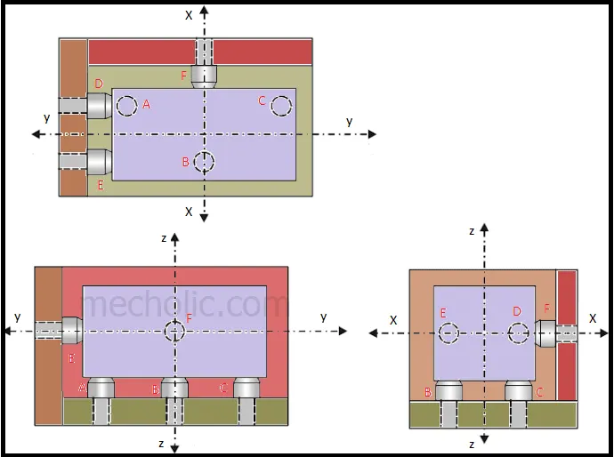
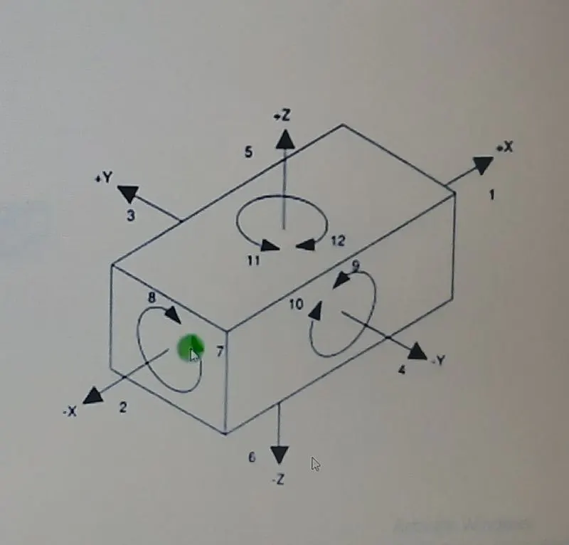
The degree of freedom defines as the capability of a body to move. Consider a rectangular box, in space the box is capable of moving in twelve different directions (six rotational and six axial). Each direction of movement is counted as one degree of freedom. i.e. a body in space has twelve degree of freedom.
Above figure shows a body in space and its possible direction of movement. The body can move two directions along the each axis of three mutually perpendicular axes; also can rotate about this axis either clockwise or anticlockwise. There are twelve degree of freedom for a body in space.
In machining process, in order to attain specific results, the degree of freedom is constrained by using work holding devices, jigs and fixture and locating devices.
PROCEDURE :
| 1.Importing the model & checking the continuity of class A surface |
We will be recieving a styling class A surface from styling team who deveopes it from a concept sketch to aesthatic class A with styling software for eg:ALIAS.here our work is to get the class A and import it to the design tool to develop Class B & C surfaces.
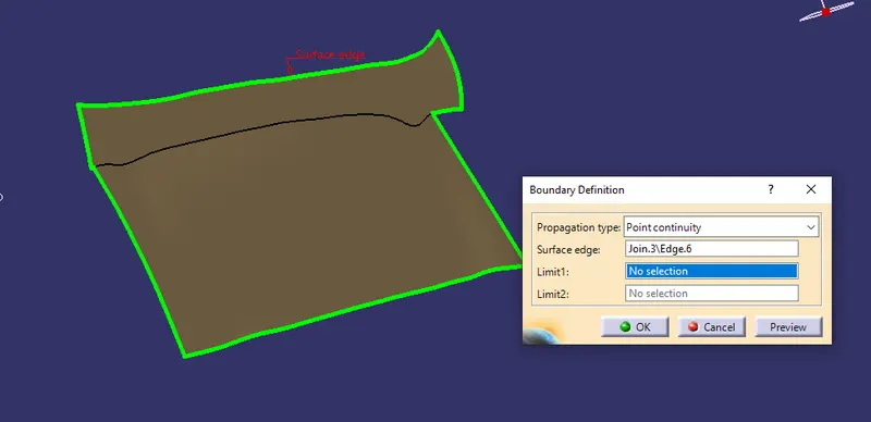
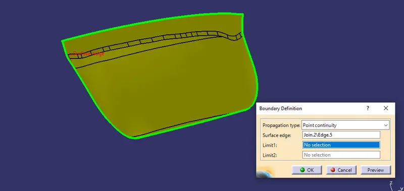
the image below shows class A surface that we have imported.here we can see there are two surfaces one is for mounting features and other for reference.
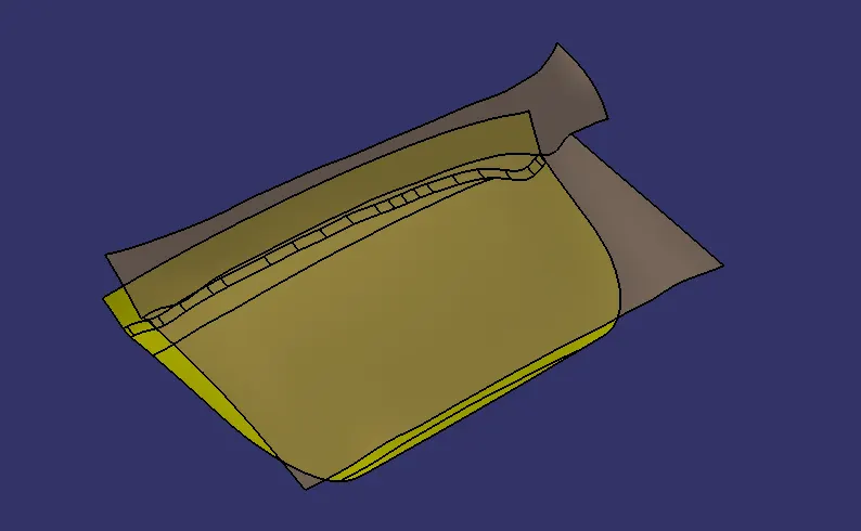
But before that we have to check continuity of given class A surface to ensure class A surface is properly joined or no discontinuity present. This can be done by using join or boundary command. By looking visually in below image we see that surface has continuous connected boundary as highlighted by green.
 |
 |
| 2. TOOLING AXIS |
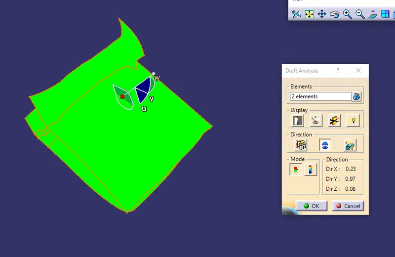
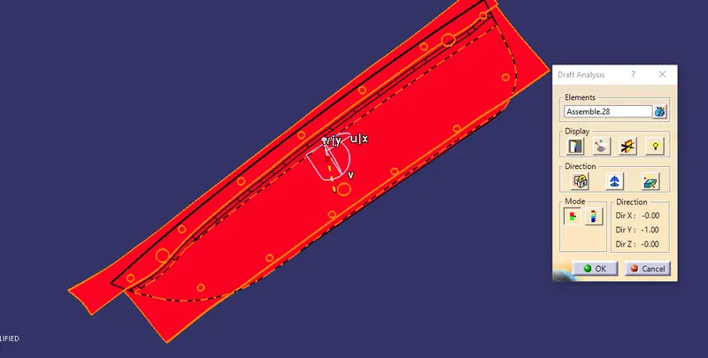
Now,draft analysis was carried out on the final body by inserting a Feature draft analysis. It was important that the part body was in customize view with material mode on. The first step was to turn on the compass option and to drag the compass and place it on the tooling direction in the correct orientation. Once it was placed, it has to be locked in that position. Then an 'x' cursor appears as we hover over the body and by clicking on it, the draft analysis is shown. The color code was red - negative, blue 0-3 degrees, and green above 3 degrees. Three degrees were chosen since it is the ideal draft angle for plastic components. The body was green which meant that it was a good design and that it would not cause any problems when the part is being extracted from the mould.
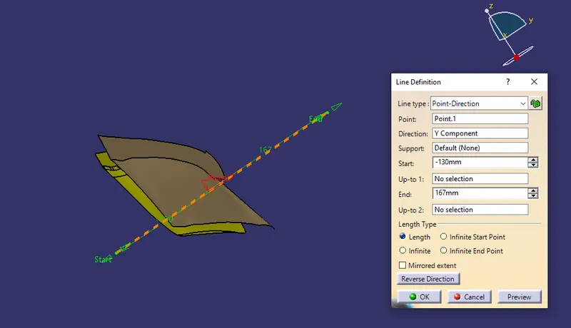
Now, we know the know Y direction is from where the tooling axis is going to lie but we don’t know the direction for the axis.So, the base is extracted and the point is created at the 0 coordinate (center of the surface). Then at this point, a line or axis is created in the Y direction.
|
3.Class B surface: |
Extract the plane surfaces from the class A surface neglecting the fillet surfaces.Untrim the surfaces from the extracted surfaces to get the actual shape of the surfaces. The Untrimmed surfaces should be intersecting with each other. If not intersecting extrapolate the surfaces.
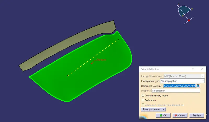
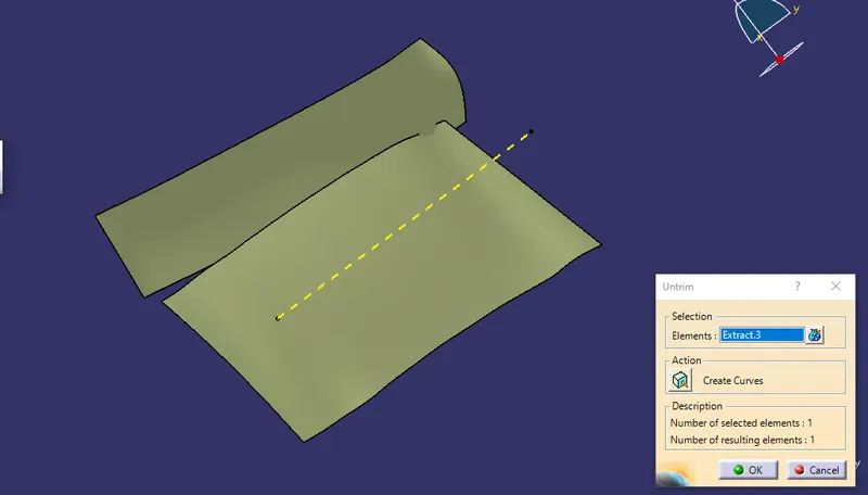
The thickness of the component is to be maintained at 2.5mm. So Offset the Extrapolated surfaces setting 2.5 mm as the offset value.Trim the surfaces as per the shape of the Class A surface.
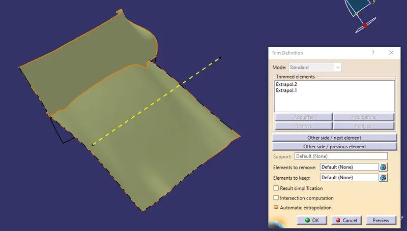
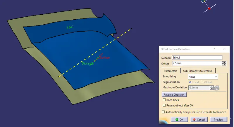
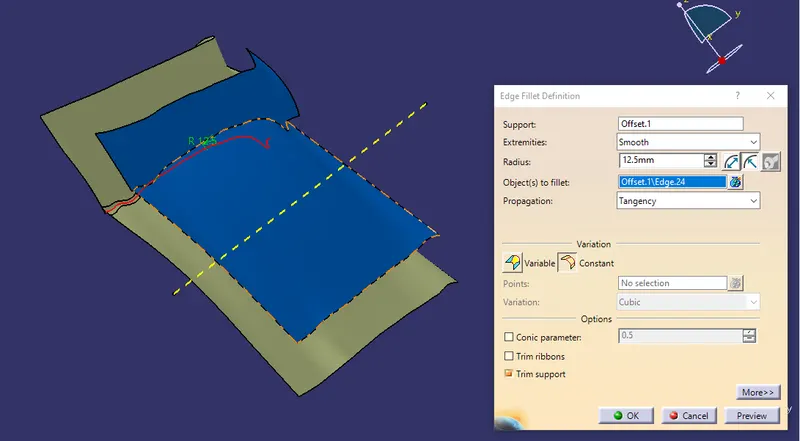
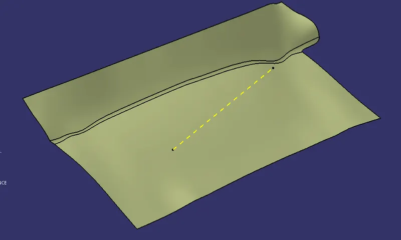
Create fillet for the component as per the class A surface. Measure the edge of the fillet value from the class A surface by extracting the fillet surface and untrimming the surface.Create fillets for the class B surface and make sure the thickness between the fillet surfaces are maintained the same as the remaining surfaces.
| 4.Class C surface : |
Extract the edge lines for the class A surface using multiple extract option.Create edge surface form class A surface using sweep option. Set the sweep mode to draft direction, select the extracted lines as guide curves and the tooling axis as the draft direction. Set the sweep angle as 3 degrees and the length of sweep more than 2.5 mm.
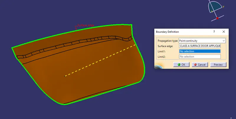
Now trim the class B and C surfaces as required to create a thickness of the component. After trimming the Class B and C surfaces join the Class A surface together.Check for any kind of open edges between the joined surfaces using the boundary feature. Fix the open edges if any.
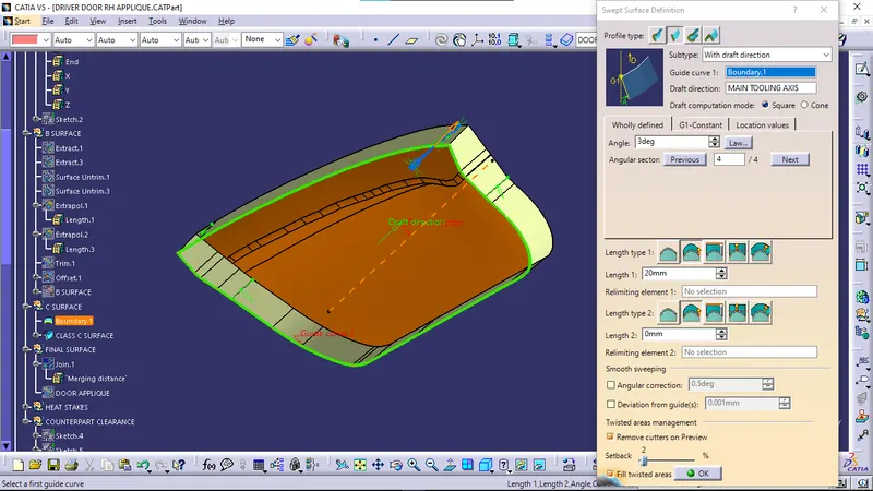
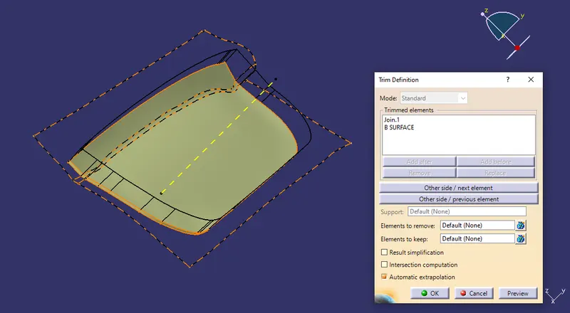
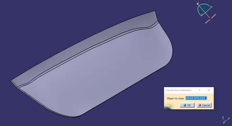
Now create a solid component for a closed surface component using the ‘Closed’ feature in the part design window. The solid will not be formed if there are any kind of open edges.
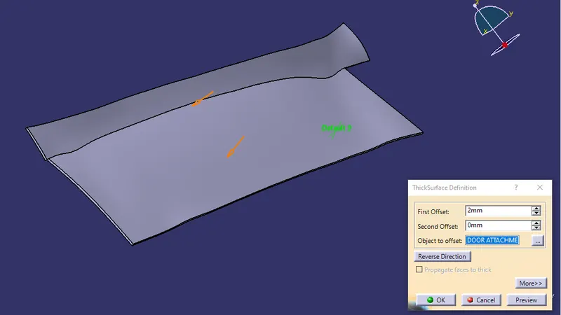
Another method for creating a solid component from the surface is to use the thickness option and mentioning the distance of the thickness and creating a draft angle on the edges walls of the surface as 3 degrees.Create a solid component for the door attachment surface sample using the thicken option.
Now the engineering features i.e., locators and heat stakes should be created for the component.
|
5.ENGINEERING FEATURES |
- Creating 2 and 4 way locators :
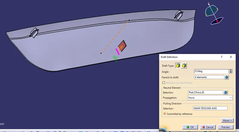
Now the 4 way and 2 way locators can be made with given guide lines.To create a 4 way locator we make a sketch of 4 and 2 way locator after that pad it to some distance and make a nuetral element for to get a exact at the middle of the component.
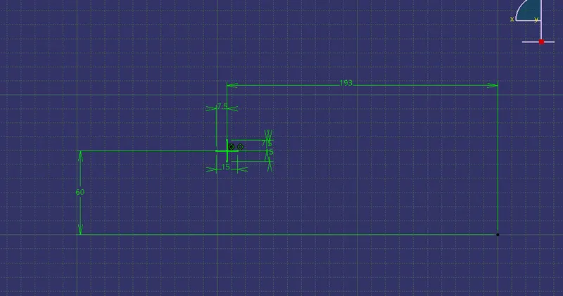
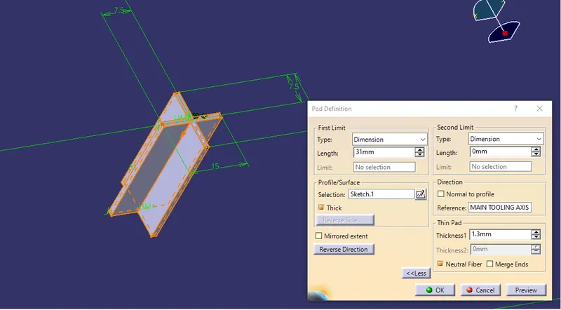
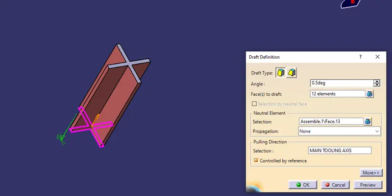
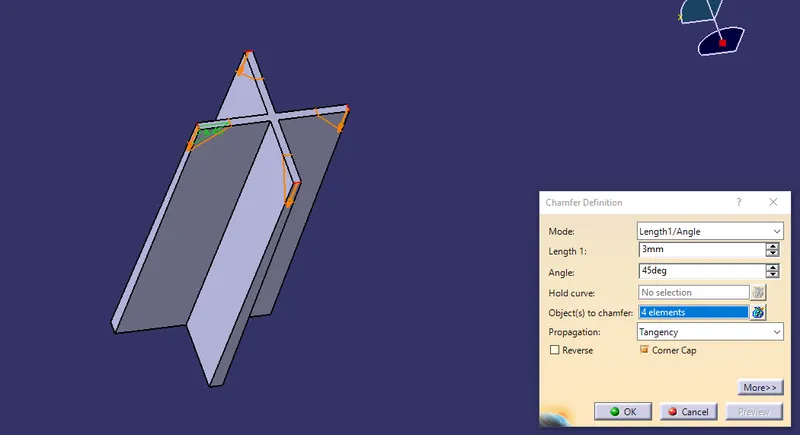
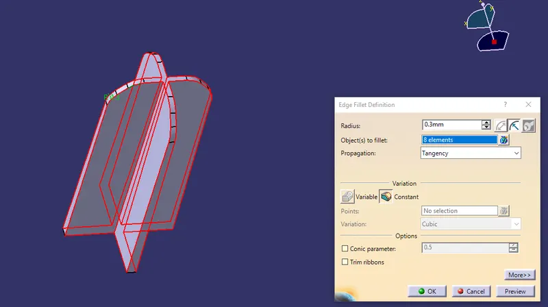
after creation of 4 way locator we shall move it to a distance by copying the same 4 way locator and paste it from main body and paste special it and make as a result and translate it to a distance from the coordinates by changing the direction of coordinates and move across the surfaces.
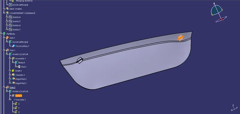
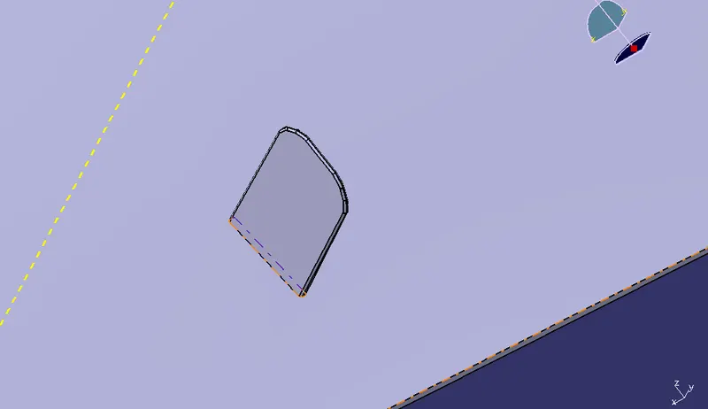
we follow the same process done for 4 way loactor i.e., construct the 2 way locator in the middle of the component by taking a single line on it and pad it to some distance and make a nuetral element so to get it at exact at middle of the component.
Creating Heat stakes :
Heat Staking is a pulsed-heat process to join two or more parts out of which one at least is made of plastic. The process is to deform the plastic material using heat and force at a set process time. The bond is made by partially de-forming the plastic part in order to fix the other.
To create a heat stakes take a sketch on door applique surface and make two circles on it by saying outer circle and inner circle with a minimum diameter for both surfaces like 5mm for the inner
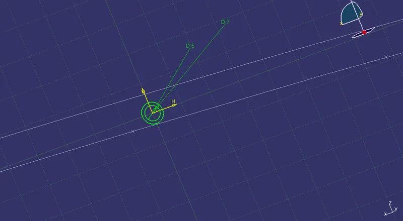
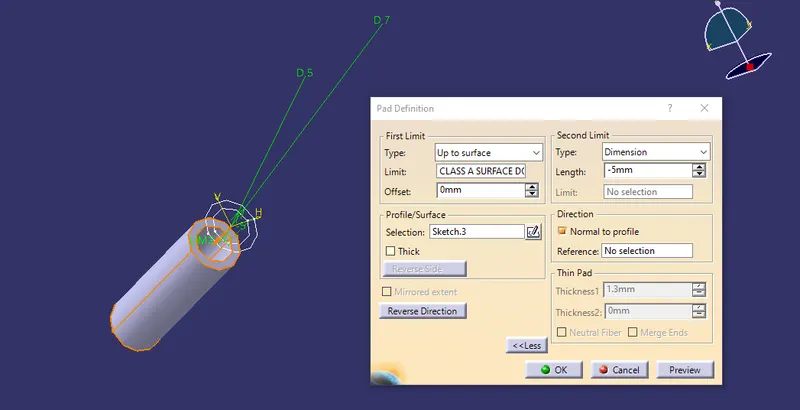
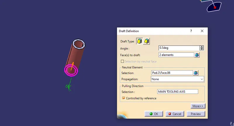
Pad these two circles with a minimum distance and place it on surface and union trim for the pad and make it visible for the component.
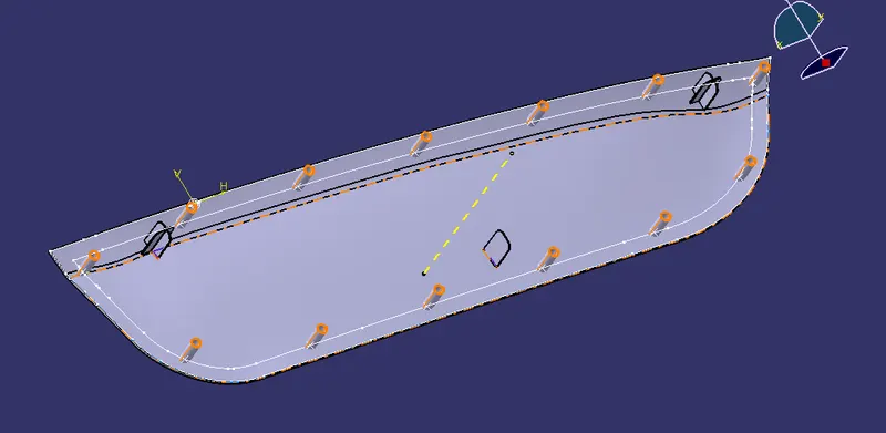
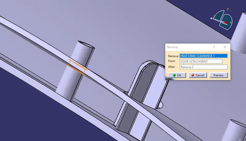
Once done with the design of locators and the heat stakes we need to design the counter holes in the mating parts with standard clearances as shown in picture below.
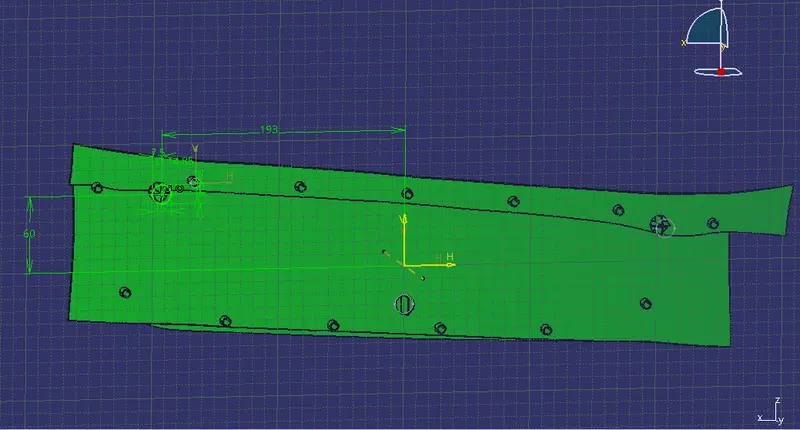
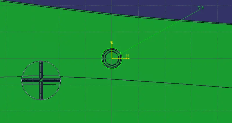
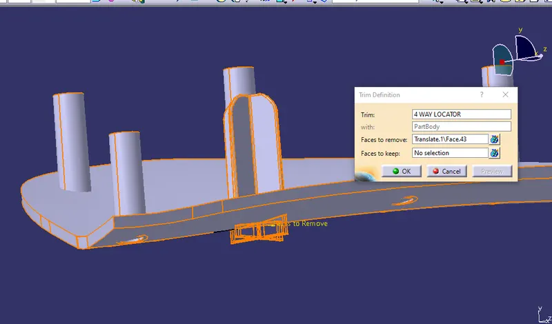
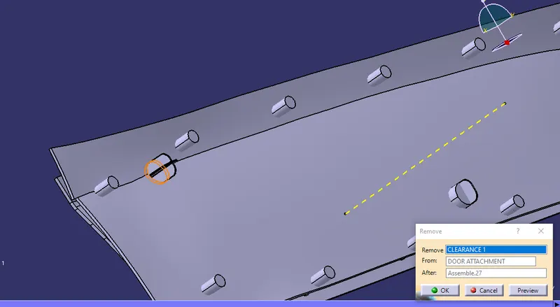
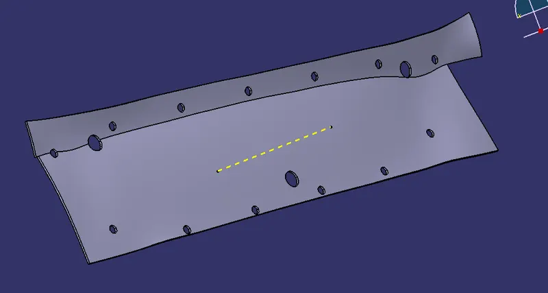
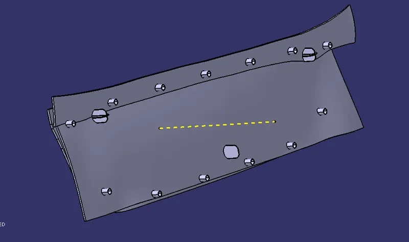
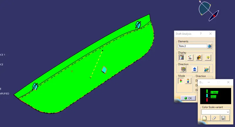
After creation of 4 way locator and 2 way locator and heat stakes we should consider for draft analysis of the component to see it should satify the draft analysis conditions and ready for manufacturing process.
- Performing draft analysis on final component.
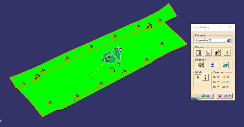
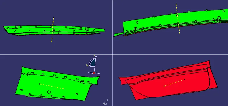
Now,draft analysis was carried out on the final body by inserting a Feature draft analysis. It was important that the part body was in customize view with material mode on. The first step was to turn on the compass option and to drag the compass and place it on the tooling direction in the correct orientation. Once it was placed, it has to be locked in that position. Then an 'x' cursor appears as we hover over the body and by clicking on it, the draft analysis is shown. The color code was red - negative, blue 0-3 degrees, and green above 3 degrees. Three degrees were chosen since it is the ideal draft angle for plastic components. The body was green which meant that it was a good design and that it would not cause any problems when the part is being extracted from the mould.
Below i have attached the Screenshots of the Draft analysis
Note : before submission of model i make sure that i have included all the things are listed below
Ensure Proper Tree StructureGeometrical sets should have a proper name based on the sketches present inside of itAll the sketches should be created under the Geometrical setUse the Close Surface feature to make a solid body from the surface.Publications: Use the publication option and publish the belowTooling AxisClass A, B, and C surface
Screenshots of the Draft analysis report for both the given Class-A surface and the final plastic componentScreenshots of the solid model with the proper color code of the draft angle in various orientations (Isometric, Front, Side, and Top View)Submission as attachmentCATpart should be submitted as an attachment using the below Browse option.
RESULT :
Finally, i have created the Base Bracket Plastic component through the given Class-A surface. and created the tooling axis for the given Class-A Surface meeting the requirements of the draft angle and at the end & and then i have created the Heat Stakes and the locators considering the design rules for the door applique and then performed the Draft analysis on the model.