Door Applique Design with Engineering Features
Door Applique Design with Engineering Features
This report demonstrates the design of an Automotive Plastic Component – Driver Side RH Door Applique Design with 4-Way, 2-Way Locators and Heat Stakes using industry principles and Design Rules. Concepts such as Rib design rules, Draft angles, Draft Analysis, Determining the Tooling Axis, Class A, Class B and Class C surfaces. The component is designed to manufacture maintaining a wall thickness of 2.5mm for Applique using Surface Design and Solid Design techniques in CAD package CATIA V5.
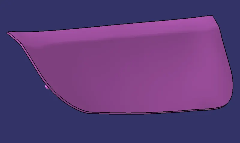
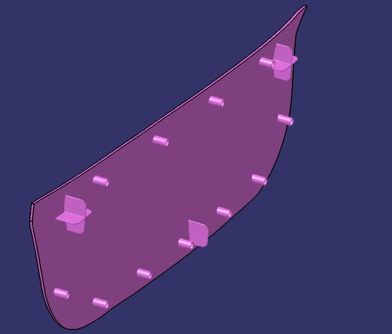
Figure1: Driver Side RH Door Applique
Design Rules for Plastic Components:
- Nominal wall thickness of a plastic component is 3mm. For a strength component such as Instrument Panel, Bumper , door trims the values of thickness are larger than 4mm. For example, Thickness of IP may lie between 5-6mm, for Bumper it may be 6-8mm. For smaller components the thickness may be between 2-3mm as in this case of Coin Holder.
- Deviation of `30% from the wall thickness is allowed with gradual increase or decrease to avoid any plastic defects while manufacturing. For example: A component having wall thickness 3mm should deviate within the range of 2.1 mm minimum and 3.9 mm maximum.
- Ideal draft angle should be 3º for the overall component along for the faces lying in the tooling direction.
Rib:
- Rib is a B-Side Engineering feature which provides a means to economical Stiffness and Strength in Plastic Molded parts without increase in overall wall thickness.
- Rib also facilitates locating and arresting components of an assembly.
- It provides alignment in Mating Parts.
- It acts as Stop and Guides for Mechanisms.
Guidelines For Rib Design:
- Proper Rib design is necessary to avoid plastic defects which involves the following critical issues that needs to be considered which are:
- Draft angle
- Rib Thickness at base
- Thickness at Top of the Rib
- Rib Height
- Location of Ribs and Spacing between 2 Ribs
- Optional Radius or Fillet Radius
- Rib Root Diameter
- Quantity of Ribs
- Manufacturability
- These guidelines are separate for Show and No – show surfaces.
- The below table gives specific values for both cases.
- Consider ‘t’ as wall thickness of base for component.
Table1: Rib Design Guidelines
|
Rib Specification |
No-Show Surfaces |
Show Surfaces |
|
Draft Angle |
Min 0.5º per side, Recommended 1.5º per side |
0.5º per side |
|
Rib Thickness at Base (w) |
0.5 * t |
0.4 * t |
|
Rib Thickness at top |
Min 0.75mm |
Min 0.75mm |
|
Rib Height (y) |
Max 5*t |
Max 5*t |
|
Spacing Between 2 Ribs (x) |
2*t |
2*t |
|
Fillet Radius (r) |
0.125*t |
Max 0.25mm |
|
Rib Root Dia |
± 30 % of t |
± 30 % of t |
|
y/x ratio for multiple ribs |
3:1 2:1 preferred |
3:1 2:1 preferred |
4 Way and 2 Way Locators:
- Locators are used to locate a job or a component to arrest its degrees of freedom using the 3-2-1 Principle which is arresting of 3 DOF's first, then 2 DOF's and last DOF in a sequence.
- A 4 way locator will look like a '+' and a 2 way locator will look like a '-' .
- Both these locators use the same Rib Design Rules and principles.
- These Locators are placed on the B side of the component and must have same height with respect to the B surface.
Heat Stake:
- In manufacturing products with Thermoplastic Components, it is often necessary to join a thermoplastic to a part having dissimilar material such as a metal or any other thermoplastic.
- Heat staking is an assembly method that uses the controlled melting and reforming of plastic stud or boss to capture or lock another plastic or metal component of assembly in place.
- The Plastic Stud protrudes through a hole in the component to be locked in place.
- Heated thermal tips are used to melt the top of the studs which fills up the volume of the cavity to produce a head locking the component in place.
- The progressive melting of plastic under continuous pressure forms the head.
- When staking, the right combination of heat and pressure is critical.
In short the Locators locate the component and lock 11 degrees of freedom whereas the Heat Stake is a Fixation which locks the Final DOF.
Draft:
- Draft is an angular tapering given at the design stage to every Plastic Component that has to be manufactured.
- It is given in the direction of the Mold Movement.
- The Draft allows the parts to release easily from the mold without creating friction between the surface of component and the core and cavity plates.
- When a Plastic component cools down inside the mold, the natural tendency of it is to shrink and attach to the core or cavity half.
- The movement of mold opening causes friction on the walls of the component as well as the core/cavity blocks.
- This reduces the life of the mold as well as the component itself.
- The component may also have rough surface finish as well as weak structure due to this.
- This problem can be solved by giving draft to the component.
- Most applications require minimum draft angles of around 0.5º to 1º , however 3º draft angles are widely accepted for cost saving purpose.
- 7º Draft angles are given to textured surfaces like Instrument Panels.
- Minimum possible draft angles are given to screw bosses, ribs and stiffeners due to their critical nature.
- Walls having 0º or negative draft are difficult to manufacture thus, are required to redesign from the Class A stage.
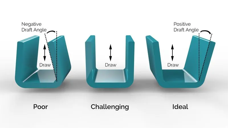
Figure2: Draft Angles
Tooling Axis:
- Tooling Axis is the direction in which the Mold opens and closes.
- Part Drafts are given along this axis for smooth ejection of parts from mold.
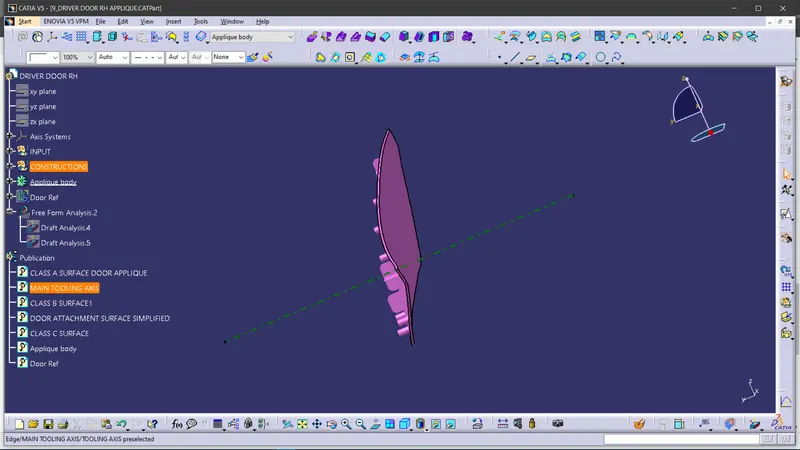
Figure3: Tooling Axis
Draft Analysis:
- Draft Analysis is a tool in CATIA which identifies the zones which deviates from the specified values of angles along a defined draft direction using colour codes.
- It highlights the regions of draft using colours.
- Draft analysis is the first step performed after receiving the Class A of the component.
- Draft analysis should be passed in order to make the plastic component manufacturable.
- Acceptable draft angles are used as range for draft analysis.
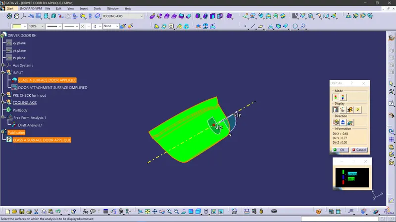
Figure4: Draft Analysis on Class A of Applique
Class- A Surface:
- In automotive design, a class A surface is any of a set of freeform surfaces of high efficiency and quality. It is the visible aesthetic surface of any automotive component.
- Class A surface refers to those surfaces which are visible and abide to the physical meaning, in a product.
- This classification is primarily used in the automotive and increasingly in consumer goods industry.
- It is a requirement where aesthetics has a significant contribution.
- For this reason, the exterior of automobiles is deemed Class-A.
Class- B Surface:
- Class B surfaces are Engineering Surfaces which are invisible to the eyes or often on the back side of the Class A surfaces.
- It is mainly the thickness of the component or Class A.
- These surfaces need to be designed as per the Class A surface i.e., the continuity, thickness of the component, functionality etc should be maintained.
- These surfaces include the main engineering features such as Screw bosses, Ribs, Snaps, Stiffeners and fixations.
- B surfaces also do not contain any aesthetic styling content and textures since it is not visible to eyes.
Class- C Surface:
- Class C surfaces are connectors between Class A and B surfaces.
- This surface connects both A and B surfaces along or angled to the Tooling Axis.
- It contains the draft as per the design.
- It is basically the thickened surface between both A and B surface.
- Below Figure 5 shows class A,B and C surfaces: Yellow surface is Class A, Purple surface is Class B and Red surfaces are Class C surfaces.
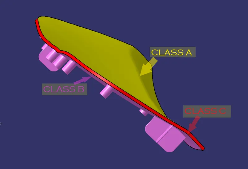
Figure5: Depiction of Class A, Class B and Class C surfaces
APPLIQUE DESIGN:
Procedure to be followed:
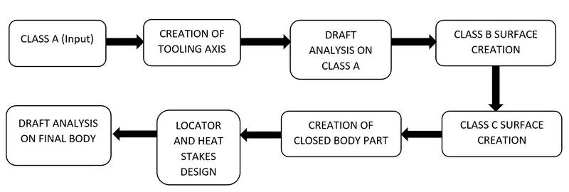
Figure6: Procedure in designing Applique
Step 1: Design Check on received Class A:
- After receiving the Class-A for the Applique check for the connectivity of the surfaces on it.
- Use Join operation, boundary operation and disassemble.
- The check is over if any discontinuities do not arise.
Step 2: Determine the Tooling Axis:
- Identify faces which can potentially create problems while manufacturing.
- Surfaces at angles along a desired Tooling Axis.
- Extract a plain surface and create a point on its center for Axis system creation.
- In this case Y axis can be a possible Tooling Axis Direction.
- Also there are no negatively angled problematic walls, so the tooling axis is created along Y axis as shown in Figure7.
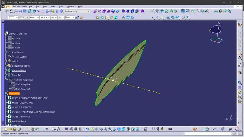
Figure7: Tooling Axis for Applique
Step 3: Perform Draft Analysis on Class A Surface:
- Change View Mode Customization to Material mode
- Go to INSERT ---> ANALYSIS ----> FEATURE DRAFT ANALYSIS and move the compass to the Tooling Axis.
- Change the range to 2.9º.
- Apply the settings as Shown in Figure 8.
Figure8: Draft Analysis on Class A of Applique.
Step 4:Class B Surface Creation:
- Extract the relevant surfaces from Class-A surface which excludes the Fillets.
- Here the selected faces consist of 2 walls.
- Extract of these surfaces is shown in the Figure 9.
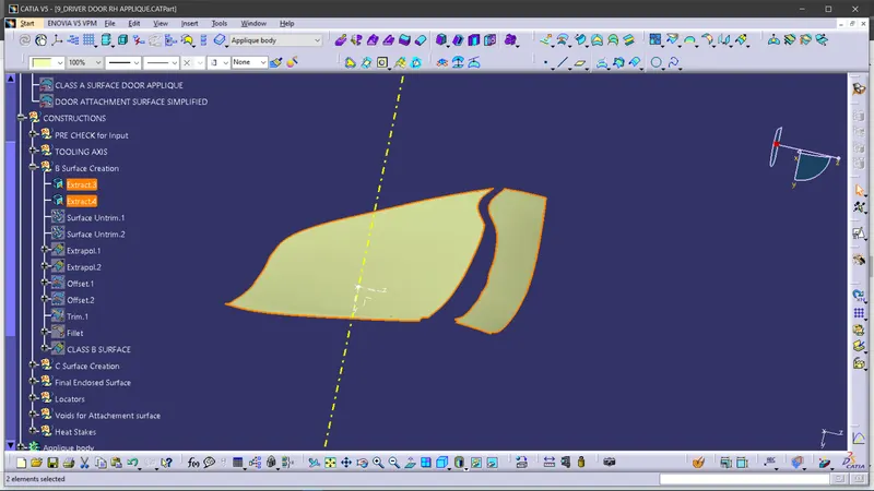
Figure9: Extract of surfaces from Class A of Applique.
- Use Untrim Command to untrim the extracted surfaces and create a natural extend.
- It is shown in Figure 10.
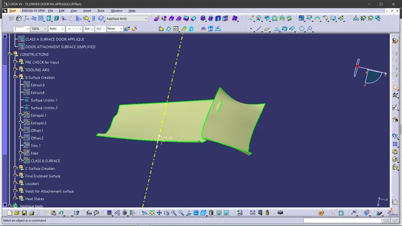
Figure10: Untrim of Extracted Surfaces.
- Extrapolate the untrimmed surfaces so that they intersect clearly and pass way forward than the Class A which will help in its trimming in further operations.
- The operation is shown in Figure 11.
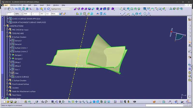
Figure11: Extrapolated Surfaces created from Untrimmed Surfaces.
- Offset the extrapolated surfaces to the value of required Thickness of the Part.
- In this case of Applique the thickness is considered as 2.5mm.
- The offset faces are the part of B-Surface highlighted in Purple.
- The operation is shown in Figure 12.
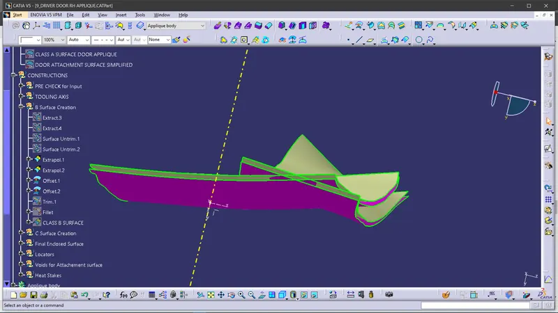
Figure12: Offset highlighted in Purple.
- Trim the extra surfaces to obtain similar extended surfaces as in Class A.
- The surface obtained after trim is shown in Figure 13.
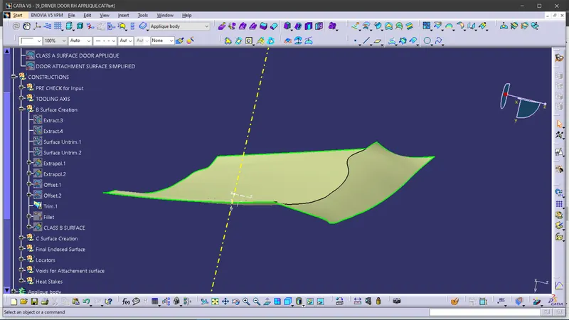
Figure13: Surface obtained on Trimming of Extrapolated Surfaces.
- Create Fillets while maintaining the part thickness between the Class A and Class B surfaces.
- The Value of Fillet is given by the equation (B surface fillet = A surface fillet ` Thickness of the Part).
- The sign + or – must be decided so as to maintain the part thickness which in this case is 2.5mm.
- The operation is shown in Figure 14.
- The obtained surface is the required Class B Surface highlighted in Light Brown as shown in Figure18.
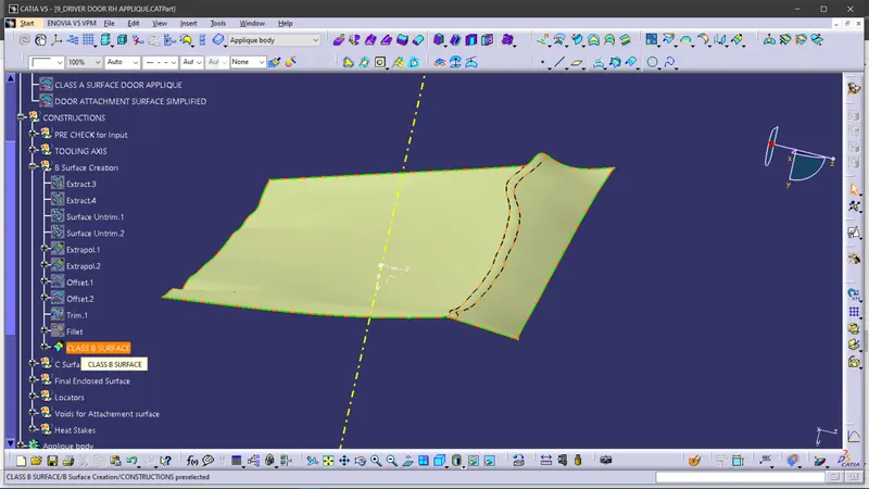
Figure14: Class B Surface
Step 5: Class C Surface Creation:
- Extract the edges of the A surface seperately as shown in Figure 15
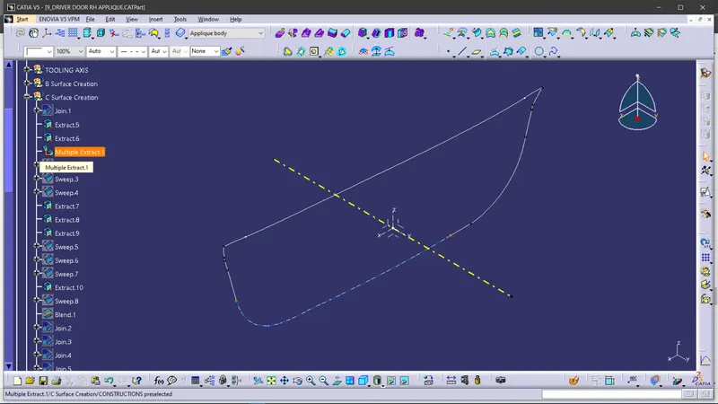
Figure15: Extract of Class A boundary.
- Use Sweep Operation to extrude the boundary using the ‘With Draft Direction’ option and selecting the boundary for Guide curve and the Tooling Axis as Draft Direction.
- Use angle as 7º draft and select outward direction with appropriate length say 20mm as shown in Figure 16.
- Do similar Sweep Operations for other extracts seperately
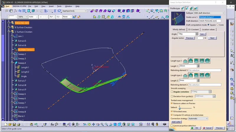
Figure16: Sweep operation for C Surface.
- Obtain the Final C Surface by joining and blending beteween the sweeps.
- The class C surface obtained is shown in Figure 17.
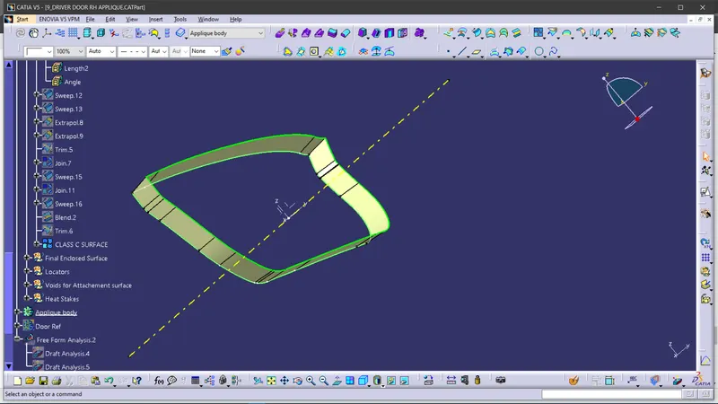
Figure17: Class C Surface.
Step 6: Final Closed Surface Creation:
- Join all the Swept surfaces along with the Class A Surface and trim it with Class B Surface.
- The Final trim should be one single Surface Entity without any gaps as shown in Figure 18.
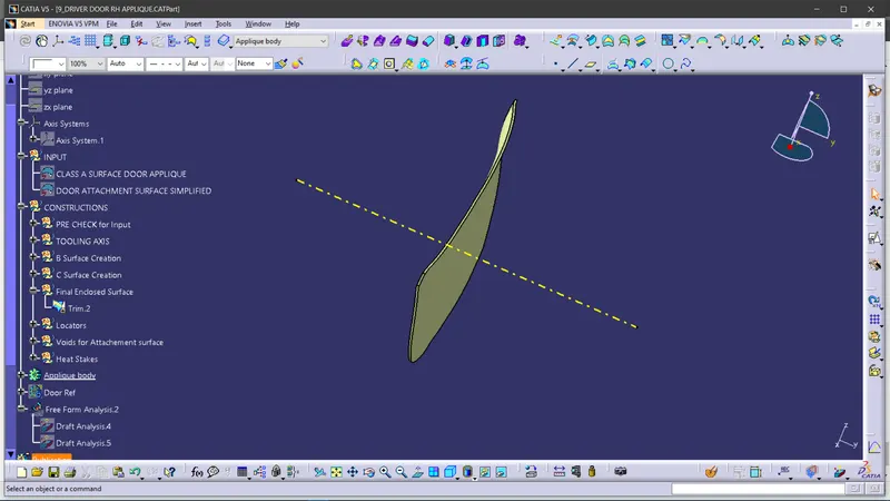
Figure18: Final Closed Surface for Applique.
Step 7: Create a Closed Body Part from Final Closed Surface:
- Switch to Part Design Workbench and use Closed Surface option to create a Solid Part from the final obtained surfaces.
- The part created is the required Applique designed from a Class A.
- The obtained solid Part is shown in Figure 19.
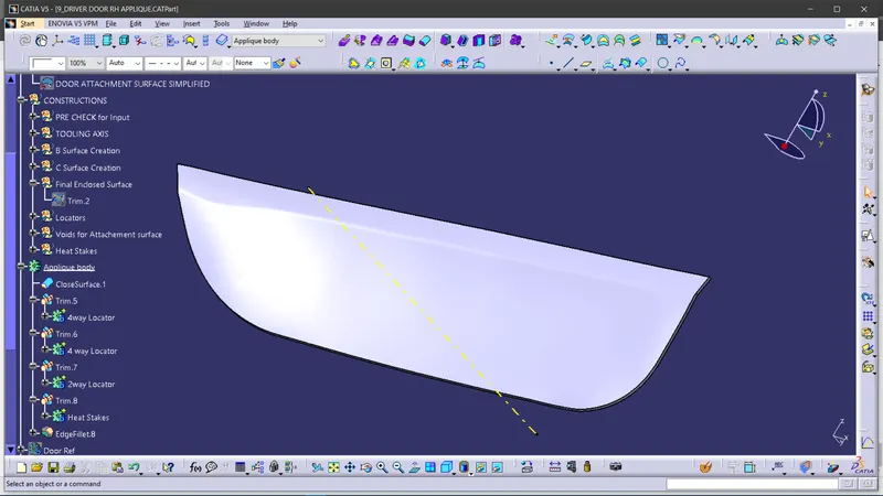
Figure19: Applique Solid Part.
Step 8: Create Locators and Heat Stakes on B Surface:
- Create a Plane on the B side.
- Create a sketch for 4 way locator as shown in Figure 20.
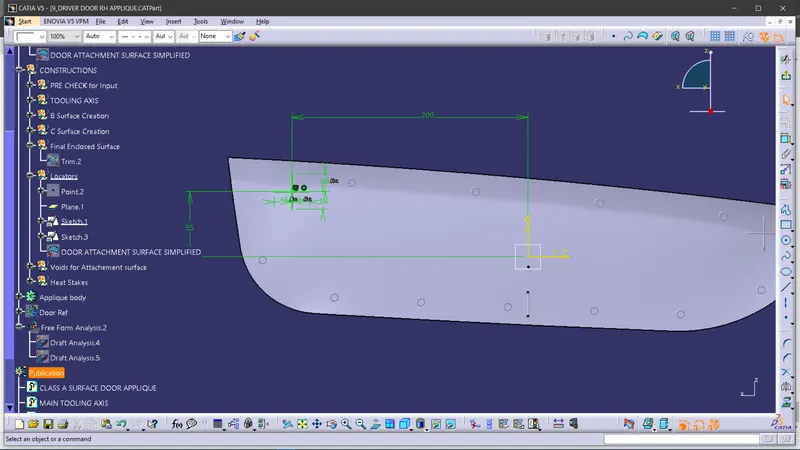
Figure20: Sketch for 4 Way Locator.
- Create a sketch for 2 way locator on the same plane as shown in a bottom location in the above figure.
- Extrude the Locators maintaining a thickness of 1.25mm as per rib design rules.
- Translate the 4 way locator to right side so that all the locators are placed equally far away.
- Make sure the height of the locator is maitained within the rib design rules.
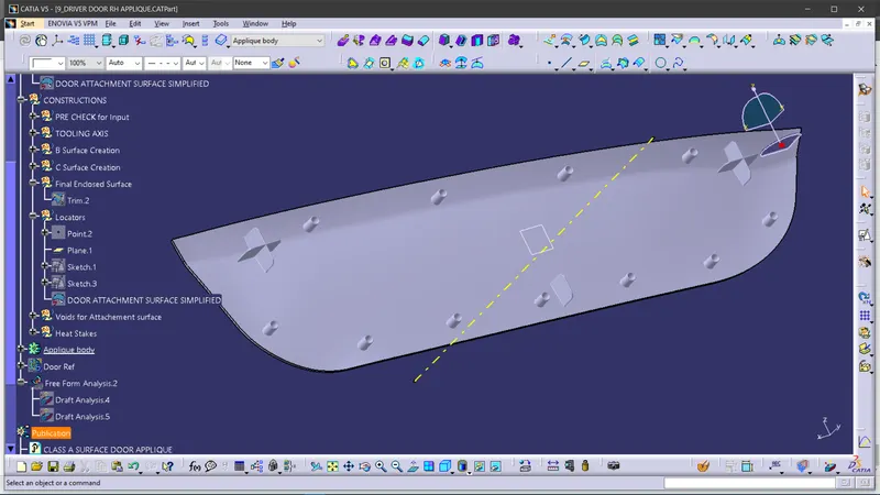
Figure21:Locators placed on B surface.
- Create a sketch of concentric circles for the Heat Stakes.
- Maintain Wall thickness as per Rib design rules and exturude the heat stakes at a level which is below the locators by at least 5mm.
- Ensure that each heat stake is at leat 50mm apart from each other
- Give Drafts of 0.5 degrees to the walls of all the locators and the heat stakes
- Use Union Trim to keep the required faces with respect to the Applique Body.
- Give Fillets to all the walls and make entry chamfers for the Locators.
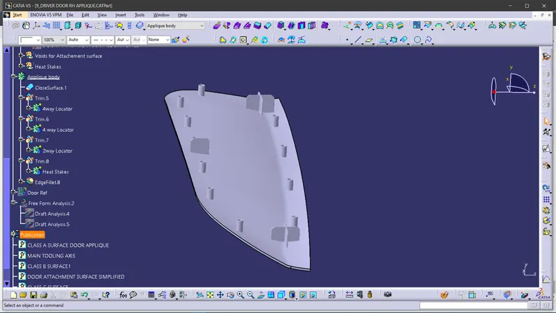
Figure22:Locators and Heat stakes placed on B surface.
- Create voids for the heat stakes and the Locators on the attachment face.
- Here the attachment face is the Door.
- thicken the Door attachement for reference.
- Create holes to accomodate the Locators and heat stakes through it.
- The hole should have maximum 0.1mm clearance with the locators and the heat stakes.
- The voids are shown in Figure 23.
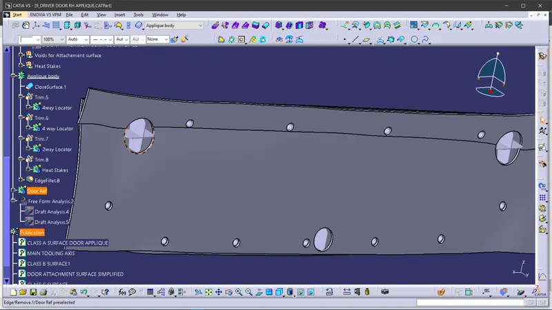
Figure23: Voids for Locators and Heat stakes placed on the attachment.
Step 9: Draft Analysis on Final Body:
- Change View Mode Customization to Material mode
- Go to INSERT ---> ANALYSIS ----> FEATURE DRAFT ANALYSIS and move the compass to the Tooling Axis.
- Change the range to 0.48º.
- Apply the settings as Shown in Figure 24.
- The Final Draft analysis passes on the whole component of Applique along the Main Tooling Axis hence it can be manufactured.
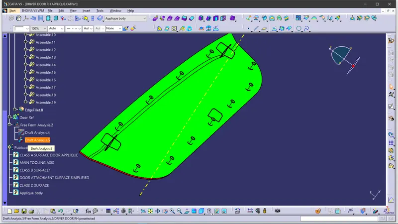
Figure24: Draft Analysis on Applique Body.
Conclusion:
The Design of Automotive Plastic Component –Driver Side RH Door Applique Design with 4-Way, 2-Way Locators and Heat Stakes has been completed by using industry principles such as Rib design Rules, Draft Angles, Draft Analysis for Class A and Final enclosed surface, Tooling Axis creation and implementation, Class B and Class C creation and conversion to a solid part.