American Chopper Motorcycle Design Project using Solidworks
Design, Assembly and Rendering of an American Chopper Motorcycle using Solidworks
Objective:
The objective of this project is to understand and demonstrate the design philosophy of a retro American chopper motorcycle model using new age design tool – Solidworks. In the design, assembly and the rendering phases, usage of sketch tools and making sure that it is fully defined, importance of mates in assembly, usage of rendering tools in Photoview 360 as well as Solidworks Visualize is completely dealt with understood.
Introduction:
American Chopper motorcycles
American Chopper motorcycles are bikes with, high rake angles and trail, low seat heights, low ground clearance, long wheelbase and long front suspension travel. The rider sits with the upper torso upright or leaning slightly rearward. The foot pegs are in such a position such that the rider has to extend his/her legs forward. Handlebars tend to be high and wide. The emphasis is on comfort while compromising cornering ability because of low ground clearance and the greater likelihood of scraping foot pegs, floor boards, or other parts if turns are taken at the speeds other motorcycles can more readily accomplish.
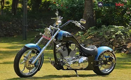
Fig1: Example of an American Chopper Motorcycle
Design tool: Solidworks
SolidWorks is a solid modelling computer-aided design (CAD) and computer-aided engineering (CAE) program published by Dassault Systems. According to the publisher, over two million engineers and designers at more than 165,000 companies were using SolidWorks as of 2013.
Solidworks has three basic environments namely: Part, Assembly and Drawing. Each of which is further elaborated below.
Part modelling or 3D solid modelling in Solidworks uses 2 approaches parametric modelling approach and feature based approach simultaneously, wherein parameters determine the shape and geometry of the solid model or the assembly. Parameters include numerical values such as lengths, diameter/radius as well as geometrical components like tangency, collinearity, parallel, concentricity, vertical, horizontal etc. Features determine the shape of the part/model as required by the user. Converting 2D sketches into 3D models requires the Feature based approach. Some features of Solidworks are extrude boss, extruded cut, revolve, revolve cut, shell, loft, sweep, hole, fillet, chamfer, slot etc.
Sketches in Solidworks include both 2D and 3D sketches. 2D sketches include splines, circles, rectangles, slots, arcs, lines etc. In 3D sketch a more complicated inter-planar curve or sketches can be created.
Using various terms from above a part/model can be created successfully.
Assembly of various parts can be done in the assembly environment. In this environment the Mates determine the final assembly and relation of various parts to each other. Mates are categorized into General, Advanced and mechanical mates. General mates determine the constraints between two parts such as concentricity, parallelism, coincidence, tangency whereas advanced mates can be used for mating chain and sprocket using width mate, gear mates for proper rotation of gears etc.
Drawing environment is mainly used to create 2D sheets with all main views of the solid parts and assembly. These sheets also include details used for manufacturing of the component such as geometric dimensions, tolerances and section views of the required part/assembly.
File Formats in Solidworks:
Parts: (.SLDPRT)
Assembly: (.SLDASM)
Drawing: (.SLDDRW). Solidworks also has products such as Photoview 360 for appearance, scenes and photorealistic renderings inside Solidworks environment and Solidworks Visualize which a Render engine for good quality image rendering.
Design methodology:
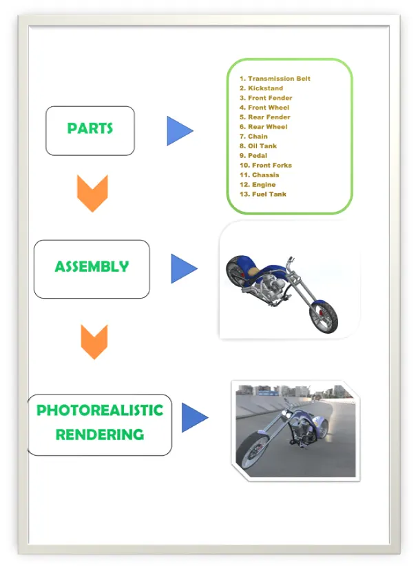 Fig2: Design methodology flowchart
DESCRIPTION:
Solid modelling of all the parts of the American Chopper Motorcycle and the sketches used as well as its features is explained in this section briefly.
- Transmission Belt:
Transmission belt is a machine component used to transmit power from one shaft/ pulley or a rotating component to another. These belts are made mostly of Rubber canvas material having upsides such as low slip, long life and low maintenance costs. The only downside of belt is power lost during transmission.
The transmission belt used in the chopper is used to drive the chain shaft driven by the engine flywheel.
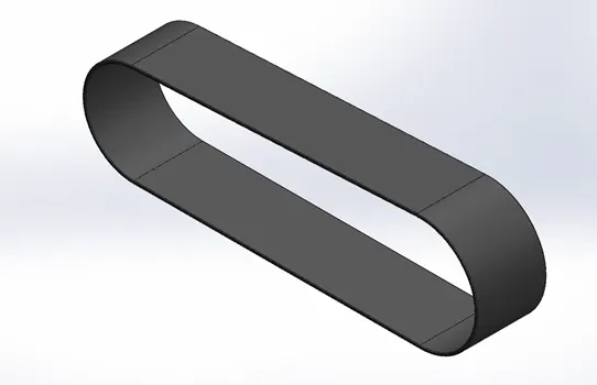
Fig3: Part model of Transmission belt
Tools Used:
Sketch tools:
- 3 Point arc
- Line
- Sketch offset
Features:
- Extrude
- Fillet
- Appearance
Procedure for modelling:
- Sketch on Front Plane - Two 3-point arcs of radius 61mm and 70mm respectively.
- Give horizontal relation between the centres of both the arcs and use Smart dimension to give a distance value of 350mm between both the centres.
- Draw lines above and below to connect both the arcs.
- Make both the lines tangent at all 4 points with the arc.
- Use sketch offset on the whole sketch of 3.5mm in outer direction.
- Extrude the sketch region Blind 88mm.
- Use fillets of 1mm on sharp edges of the belt.
- Apply appearance of Matte Rubber on the part.
- Save the part using appropriate name.
- Kickstand or Side Stand:
Kickstand or Side stand is a machine component used to support the motorcycle in rest position. The kickstand is mounted to the chassis through a mounting point. This component should have high tensile/compressive strength to withstand the load of bike while in rest position. The side stand is mounted generally on the left side of the chassis lower side and has a free movement of 90 degrees so that stand can be swayed up when not required or while driving.
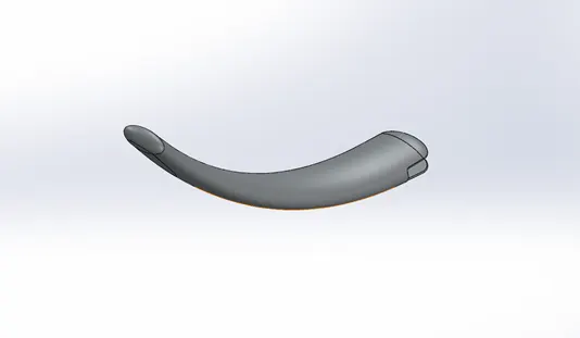
Fig4: Part model of Kickstand
Tools Used:
Sketch tools:
- Ellipse
- Spline
- Pierce
Features:
- Loft
- Split
- Dome
- Extruded Boss
- Extruded Cut
- Fillet
- Appearance
Procedure for modelling:
- Sketch an ellipse on the front plane of 40mm width and height of 18mm and make its centre point coincident to the origin.
- Sketch a spline perpendicular to the front plane giving appropriate weights.
- Create a plane perpendicular to the other end of the spline and sketch an ellipse of width 30mm and height of 12mm.
- Create a pierce relation between the ellipse and the spline.
- Use Loft feature more specifically the centre line loft by selecting the spline as the centre line and the 2 ellipses as references.
- Sketch a line on the new plane and use split feature to create a flat bottom cut for the kickstand.
- Sketch a centre point rectangle on the right plane on the origin of width 28mm and height 8mm.
- Extrude cut through all both to create a cut-out for the stand mount to the chassis.
- Sketch a circle of 9mm diameter on the cut section face and extrude boss the same up to next to create a stand mount.
- Apply fillets of 2mm and 0.5mm at appropriate edges.
- Apply the chromium plate appearance to the part and save the part as Kickstand.
- Front Fender:
A fender is an automobile part that is bound to the vehicle frame and is placed as a cover on the upper side of the tyres. Its primary purpose is to prevent sand, mud, rocks, liquids, and other road spray from being thrown into the air by the rotating tire. Front wheels require the fenders to provide mud and gravel protection on the rear side i.e., the rider side and the engine. This part is also known as mud guard.

Fig5: Part model of Front Fender
Tools Used:
Sketch tools:
- 3-Point arc
- Sketch offset
- Line
- Spline
Features:
- Revolve
- Split
- Dynamic mirror entity
- Fillet
- Appearance
Procedure for modelling:
- Rename the Front plane, Top plane and the Right plane as Vertical plane Front fender, Centre plane Front fender and Mid Plane Front fender respectively.
- Sketch a 3-point arc of radius 125mm and end points distance 160mm.
- Apply Vertical relation of origin to the centre point of the arc.
- Make the end points of the arcs horizontal.
- Apply vertical distance of 280mm from the origin to centre point of arc
- Apply sketch offset with bounds of 6mm inwards.
- Sketch a horizontal construction line along the origin.
- Revolve the closed sketch about the origin line with direction1 = 5° and direction2 = 130°.
- Sketch a centre construction line on the fender face and apply dynamic mirror entity for the line.
- Sketch a spline of appropriate dimensions on one side of the centre line of the fender face.
- Use split feature to cut parts and consume body to give a aesthetic cut on the top of fender.
- Do the similar split option on the other end of fender.
- Apply appropriate fillets on sharp edges.
- Apply appearance of painted metallic car as required.
- Rear Fender:
A fender is an automobile part that is bound to the vehicle frame and is placed as a cover on the upper side of the tyres. Its primary purpose is to prevent sand, mud, rocks, liquids, and other road spray from being thrown into the air by the rotating tire. Rear wheels require the fenders to provide mud and gravel protection on the front side i.e., the rider side and the chassis. This part is also known as mud guard.
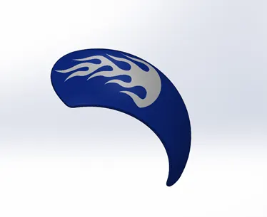
Fig6: Part model of Rear Fender
Tools Used:
Sketch tools:
- 3-Point arc
- Sketch offset
- Line
- Spline
Features:
- Revolve
- Split
- Shell
- Dynamic mirror entity
- Fillet
- Appearance
Procedure for modelling:
- Rename the Front plane, Top plane and the Right plane as Vertical plane Rear fender, Centre plane Rear fender and Mid Plane Rear fender respectively.
- Sketch a 3-point arc of radius 290mm and end points distance 364mm.
- Apply Vertical relation of origin to the centre point of the arc.
- Make the end points of the arcs horizontal.
- Apply vertical distance of 280mm from the origin to centre point of arc
- Apply sketch offset with bounds of 6mm inwards.
- Sketch a horizontal construction line along the origin.
- Revolve the closed sketch about the origin line with direction1 = 10° and direction2 = 140°.
- Sketch a 3-point arc of radius 265mm on one side of outer face of the fender, make the distance between origin and the arc centre point = 227mm.
- Use split feature to cut parts and consume body to give a aesthetic cut on the top face of fender.
- Apply fillet of 45mm on all 4 edges.
- Use shell feature with value of 4mm on inside face of the fender.
- Apply appearance of painted metallic car as required and save the part.
- Chain:
A chain is a set of several links made of small plates and pin joints, connected in a loop to make a power transmission component. This is mainly used to transmit power from one shaft to another using sprockets as connecting means to the shafts. The main advantage of chain is high power transmission capacity, good flexibility, low cost. The disadvantage of chain is high maintenance.
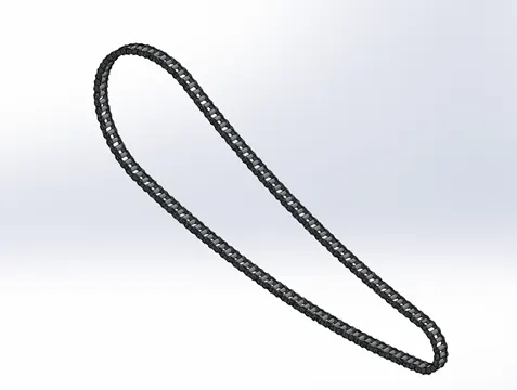
Fig7: Part model of Chain
Tools Used:
Sketch tools:
- 3-Point arc
- Centrepoint slots
- Circle
Features:
- Extruded boss
- Make and save block
- Fillet
- Curve driven pattern- tangent to curve
- Mirror
- Appearance
Procedure for modelling:
- Rename the Front, Top and Right planes to Mid Plane chain, Centre Plane chain and Front plane chain respectively.
- Sketch the chain path with two 3-point arcs of same dimensions as the rear and front sprocket with diameters of 289mm and 99mm respectively.
- Give 650mm as the horizontal dimension and 147mm as vertical dimension between the 2 arc centres.
- Join the 2 arcs from top and bottom with 3-point arcs of diameter 1500mm and keep tangency at the points.
- Create 2 chain links with pins of diameter 8mm and centre to centre distance of 15.13mm and extrude the pins midplane 25mm.
- Sketch the link plates with appropriate dimensions and extrude the plates of 1 link offset by 9.5mm and value of 2mm
- Extrude the second link selecting from the inner vertex of the 1st link and value of 2mm.
- Fillet the sharp edges of pins with value 0.5mm.
- Create a block of both the links and save it as block for future use.
- Make the centre of 1st link coincident to the tangency point of chain path sketch.
- Select Linear Pattern-Curve driven up to the next tangency point of the chain path.
- Import the saved link blocks and repeat the process of pattern separately for all new tangency points for smooth transition of chain links.
- Put all the pins in a new folder and all the plates in a different folder in feature tree.
- Mirror the plates folder across the chain path sketch.
- Apply appearance of chromium plate to the body and save the part
Oil Tank:
Oil tank is a component used to store the oil for lubrication and cooling purposes of engine components. Oil tanks can be of various kinds like engine oil tank, coolant oil tank, radiator oil tank etc. The oil tank used in this American chopper model is used for engine lubrication and cooling. This tank is placed right below the rider seat on top of the gearbox.
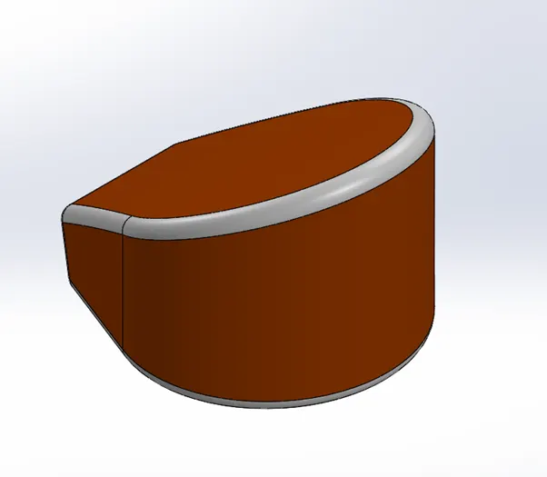
Fig8: Part model of Oil Tank
Tools Used:
Sketch tools:
- 3-Point arc
- Line
Features:
- Extruded boss/base
- Fillet
- Combine
- Shell
- Appearance
Procedure for modelling:
- Rename the Front plane to Mid Plane Oil tank.
- Start a sketch on the Top plane with a horizontal construction line of length 230mm passing through the origin.
- Sketch a line 50mm on one end of the construction line perpendicular to it.
- Sketch an angled line and complete the sketch with an arc as shown below.
- Create a reference point vertical to the origin 146mm above.
- Make the angled line collinear to the reference point.
- Make a tangent relation between the angled line and the arc.
- Mirror the whole sketch about the construction line.
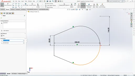
Fig9: Top plane sketch of oil tank
- Extrude the sketch blind 170mm.
- Now sketch on the midplane as shown in the picture below.
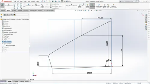
Fig10: Midplane sketch of oil tank
- Extrude this sketch through all in both directions.
- Use Combine feature and select operation type as common.
- Fillet all the edges 10mm.
- Create a shell of 3mm to create a hollow tank.
- Apply appearance white on fillet and blue on the oil tank and save the part.
- Pedal:
A pedal is a motorcycle component used by the rider to place his/her foot on it while riding the bike. This is also called foot peg and is mounted on both sides of chassis. Its position depends on the type of motorcycle. In a chopper type motorcycle, the pedals are placed in forward position such that the legs of the rider are fully extended in a comfortable manner. The pedals also contain protruded sections so as to provide grip to the rider’s foot to avoid any kind of slippage. The brakes and the gear shift pedals are mounted on each of the pedals or are nearly placed.
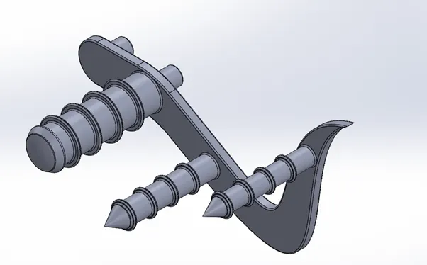
Fig11: Part model of Pedal
Tools Used:
Sketch tools:
- 3-Point arc
- Circle
- Spline
- Line
- Sketch fillet
Features:
- Extruded boss
- Revolve
- Fillet
- Dome
- Chamfer
- Linear pattern
- Appearance
Procedure for modelling:
- Create the following sketch on the front plane
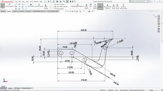
Fig12: Front plane sketch of Pedal
- Make use of sketch fillets as shown with value of Radius 60mm.
- Add spline weights as shown and make sure the tangency is maintained.
- Extrude the sketch (except the circles) blind 8mm.
- Extrude the first two circles of diameter 16mm in reverse direction 20mm and merge the results.
- Create a fillet of 1mm on both flat faces of first extruded plate.
- Sketch the following on top plane.
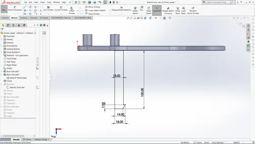
Fig13: Top plane sketch of Pedal
- Revolve the sketch and merge results.
- Create a dome of 3mm on end face of this revolved part.
- Apply fillet of 1mm on end face of dome.
- Extrude the remaining 2 circles of diameter 18mm and 15mm of primary sketch 100mm from the surface.
- Use Chamfer (distance-distance type with d1=16mm and d2=9mm) on 18mm dia boss.
- Use Chamfer (distance-distance type with d1=16mm and d2=7.5mm) on 15mm dia boss.
- Offset the circles as shown in the figure.
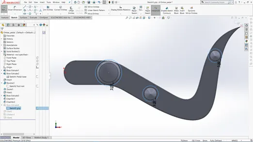
Fig14: Offset sketch
- Extrude boss the sketch with offset 20mm from the surface blind 2.5mm, fillet the face with 1mm.
- Use linear sketch pattern with spacing between instances as 20mm and number of instances as 4.
- Apply chromium plate appearance to the entire part and save the file.
- Front Wheel:
Wheel consists of the rims and the tyre which make it the component that makes connection between the motorcycle and the ground. The rim is an important strength component which ensures safe load carrying capacity of the bike. It should have high compressive strength so as to ensure safety while moving. It should be able to absorb shocks and impacts. The tyres are the main contact surface to the ground. It is generally made up of rubber to ensure flexibility and bump absorption. The tyres contain treads which provides grip to the road. The wheel also houses a Disc brake rotor and its calliper.
Front wheels of choppers are always larger than the rear wheel with narrow section as compared to the latter. The front wheel in this American Chopper has a diameter of 604mm which is approximately 23.7 inches. The tyres have a narrow section meaning narrow surface contact.
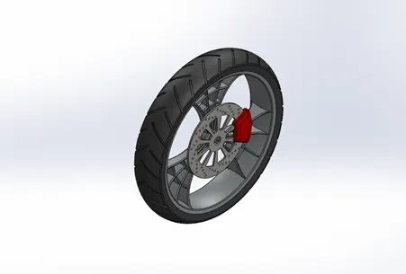
Fig15: Part model of Front Wheel
Tools Used:
Sketch tools:
- 3-Point arc
- Lines
- Splines
- Mid-point line
- Circle
- Sketch fillet
- Trim
- Extend
- 3-point centre rectangles
Features:
- Revolve boss/base
- Extrude boss/base
- Extrude cut
- Revolve Cut
- Circular Pattern
- Combine
- Fillet
- Chamfer
- Appearance
Procedure for modelling:
- Create a horizontal mid-point line of 110mm on the front plane origin.
- Sketch a 40mm vertical line on both ends of the mid-point line and close the sketch as shown in fig 16 with a line.
- Create a horizontal line of 140mm, 300mm above the origin and make its midpoint vertical to the origin.
- Create a 3-point arc and make its centred with respect to the above line and give it a radius of 230mm. Make sure that the end points of arcs have horizontal relation.
- Close the sketch with lines and give an angle of 75° and sketch fillet of 7.5mm as shown in figure 16.
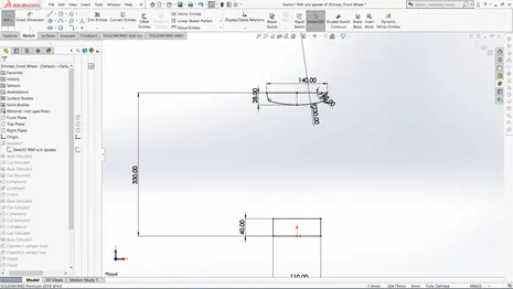
Fig16: Sketch1 on front plane of Front Wheel
- Create a centre line connecting mid-point of above line with mid-point of the arc and make sure it is vertical. Give a vertical distance of 28mm to this line.
- Make sure the sketches are fully defined and revolve the sketch about the line on origin.
- Now create a sketch on Right plane to create spokes.
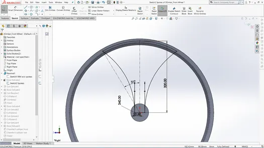
Fig17: Spokes sketch on right plane of Front Wheel
- Create the sketch as in figure 17 using splines, 3-point arc and construction lines.
- Create relations as shown in fig 18.
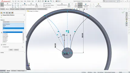
Fig18: Spokes sketch relations of Front Wheel
- Extrude boss the sketch using midplane and d1 = 122mm and do not merge the results.
- Create another sketch on Right plane and create 4 splines as shown in figure 19 and 20.
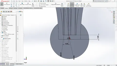
Fig19: Spokes cut out sketch of Front Wheel
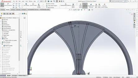
Fig20: Spokes cut out sketch of Front Wheel
- Extrude cut through all both and deselect the auto-select option from feature scope and assign only the required body to cut.
- Sketch on right plane 3 circles of Ø215, Ø 350 and Ø 485 from the origin.
- Make cob web sketches as shown in figure 21
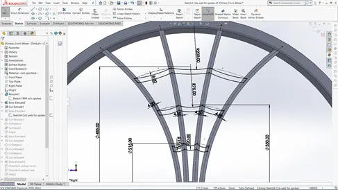
Fig21: Cob web cut out sketch of Front Wheel
- Offset the spokes 4.5mm inwards and trim the external 3 circles make it construction.
- Use the intersection points of the construction lines and the 3 circles as reference points to create cob web arcs.
- Make 3-point arcs at all intersection points.
- Give the dimensions to all arcs as shown in fig 21.
- Offset all the arcs 8mm below and trim extra.
- Extrude all the arcs up to the spoke vertex on both sides.
- Create new sketch on the Front plane.
- Convert using intersection surface- the inner face of rim on the sketch.
- Create the sketch as shown in fig22.
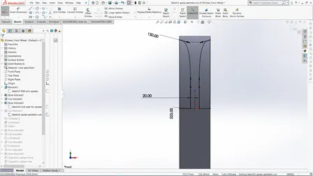
Fig22: Front plane sketch for aesthetic cut on Front Wheel
- Revolve cut the sketch about the centre line and deselect auto select in feature scope and select only required body.
- Use circular pattern of the cob web with 3 instances and select the hub as the direction of pattern.
- Combine the spokes and cob web with the revolved rim.
- Fillet the front and back face of the spokes as required.
- Model a Disc brake rotor:
- Sketch a circle on the right plane of Ø 345mm.
- Extrude it offset 45mm and blind d1=7mm and don’t merge the result.
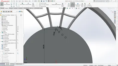
Fig23: Ventilation holes sketch for disc rotor of Front Wheel
- Create sketch as shown for the ventilation holes 160mm vertical to the origin on the face of disc.
- Use circular sketch pattern with 14 instances about the disc centre and fully define the sketch.
- Extrude cut the sketches by using up to next.
- Create new sketch on the same disc face for slot cuts.
- Sketch 2 circles about the origin with Ø 100mm and Ø 240mm.
- Sketch a line vertical to the origin to connect both circles.
- Sketch another line connecting both the circles 25° apart from the previous line.
- Trim the outer sketches and provide sketch fillets of R5 to 4 corners of the sketch shown in fig24.
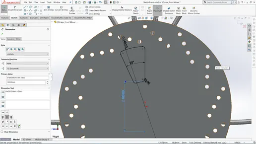
Fig24: Ventilation slot sketch for disc rotor of Front Wheel
- Extrude cut the sketch up to next.
- Use circular pattern with 10 instances about the rotor centre.
- Now sketch a circle of Ø 40mm on right plane and extrude cut it through all both to create an axle hole.
- Model the calliper for the disc brake:
- Sketch on the rotor face 2 circles of Ø 200mm and Ø 380mm.
- Sketch a vertical construction line from the centre of rotor above.
- Sketch 2 lines intersecting both circles keeping the lines 54° apart.
- Dimension an angle of 63° between the construction line and the solid line and trim the extras as shown in figure 25.
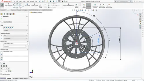
Fig25: Calliper sketch for Front Wheel
- Extrude the calliper sketch 19.5mm in d1 and 10.5mm in d2 and do not merge results.
- Chamfer both faces of calliper (distance-distance with d1=6mm and d2=20mm).
- Fillet the edges with appropriate dimensions.
- Model the tyre of front wheel:
- Sketch on the Front plane and convert entities with intersection curve and delete the bottom instance that is converted.
- Sketch a 3-point arc of Ø226mm keeping the end points of arc horizontal and at a distance of 154mm.
- Centre of the arc should be horizontal to the origin and at a distance of 7mm.
- Sketch lines to connect the end points of arc to the converted entity on top of the rim.
- Use sketch fillet of 7mm at corner points as shown in fig25.
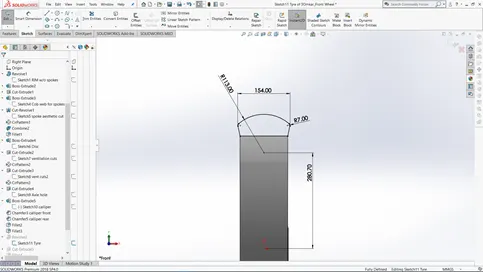
Fig26: Tyre sketch of Front Wheel
- Revolve the sketch about the Right plane centre axis line and do not merge results.
- Tyre treads sketch:
- Sketch on Front plane 2x 3-point centre rectangle of dimension138mm x 8mm.
- Sketch 2 more rectangles of dimension 90mm x 8mm.
- Convert the rim edge in to the sketch and make it construction
- Place it as shown in the fig26.
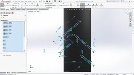
Fig27: Tyre sketch of Front Wheel
- Extrude cut the entire sketch offset 450mm and use offset from surface of tyre face 4mm. Reverse the feature and see the preview for appropriate cuts.
- Keep the feature scope to the tyre only.
- Use Round fillets on the tread edges to make it look smooth.
- Use circular pattern for the tread cuts around the centre of tyre/hub with 14 instances.
- Apply the following appearances:
- Candy red apple car paint for calliper
- Chromium plate for rims and spokes with cob web design.
- Chromium plate for Disc brake rotor.
- Matte rubber for the tyre.
- Save the part as Front wheel.
- Rear Wheel:
Wheel consists of the rims and the tyre which make it the component that makes connection between the motorcycle and the ground. The rim is an important strength component which ensures safe load carrying capacity of the bike. It should have high compressive strength so as to ensure safety while moving. It should be able to absorb shocks and impacts. The tyres are the main contact surface to the ground. It is generally made up of rubber to ensure flexibility and bump absorption. The tyres contain treads which provides grip to the road. The rear wheel also houses a Disc brake rotor and its calliper and specifically a Chain sprocket to drive the wheel using power transmitted from engine.
Rear wheels of choppers are generally smaller in diameter than the front wheel having a broad section as compared to the latter. The rear wheel in this American Chopper has a diameter of 484.5mm which is 19 inches. The tyres have a broad section meaning broader surface contact, heavy load carrying capacity and greater grip.
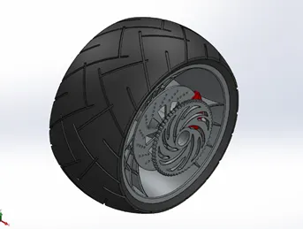
Fig28: Part model of Rear Wheel
Tools Used:
Sketch tools:
- 3-Point arc
- Lines
- Splines
- Mid-point line
- Circle
- Sketch fillet
- Trim
- Extend
- 3-point centre rectangles
Features:
- Revolve boss/base
- Extrude boss/base
- Extrude cut
- Revolve Cut
- Circular Pattern
- Combine
- Fillet
- Chamfer
- Appearance
Procedure for modelling:
- Create a horizontal mid-point line of 300mm on the front plane origin.
- Sketch a 45mm vertical line on both ends of the mid-point line and close the sketch as shown in fig 29 with a line.
- Create a horizontal line of 320mm, 273mm above the origin and make its midpoint vertical to the origin.
- Create a 3-point arc and make its centred with respect to the above line and give it a radius of 600mm. Make sure that the end points of arcs have horizontal relation with each other.
- Close the sketch with lines and give an angle of 75° and sketch fillet of 5mm as shown in figure 29.
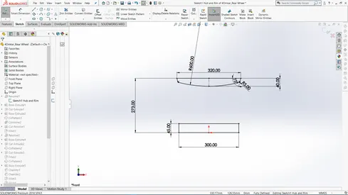
Fig29: Sketch1 on front plane of Rear Wheel
- Create a centre line connecting mid-point of above line with mid-point of the arc and make sure it is vertical. Give a vertical distance of 40mm to this line.
- Make sure the sketches are fully defined and revolve the sketch about the line on origin.
- Now create a sketch on Right plane to create spokes.
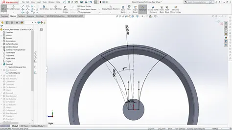
Fig30: Spokes sketch on right plane of Rear Wheel
- Create the sketch as in figure 30 using splines, 3-point arc and construction lines.
- Create relations as shown in fig 31.
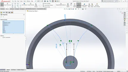
Fig31: Spokes sketch relations of Rear Wheel
- Extrude boss the sketch using midplane and d1 = 300mm and do not merge the results.
- Create another sketch on Right plane and create 4 splines as shown in figure 32 and 33.
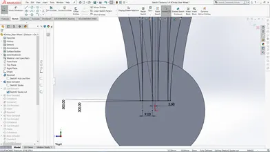
Fig32: Spokes cut out sketch of Rear Wheel
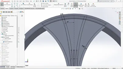
Fig33: Spokes cut out sketch of Front Wheel
- Extrude cut through all both and deselect the auto-select option from feature scope and assign only the required body to cut.
- Sketch on right plane 3 circles of Ø194, Ø 298 and Ø 403 from the origin.
- Make cob web sketches as shown in figure 34
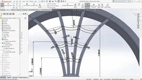
Fig34: Cob web cut out sketch of Rear Wheel
- Offset the spokes 4.5mm inwards and trim the external 3 circles make it construction.
- Use the intersection points of the construction lines and the 3 circles as reference points to create cob web arcs.
- Make 3-point arcs at all intersection points.
- Give the dimensions to all arcs as shown in fig 34.
- Offset all the arcs 8mm below and trim extra.
- Extrude all the arcs up to the spoke vertex on both sides.
- Create new sketch on the Front plane.
- Convert using intersection surface- the inner face of rim on the sketch.
- Create the sketch as shown in fig35.
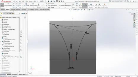
Fig35: Front plane sketch for aesthetic cut on Rear Wheel
- Revolve cut the sketch about the centre line and deselect auto select in feature scope and select only required body.
- Use circular pattern of the cob web with 3 instances and select the hub as the direction of pattern.
- Combine the spokes and cob web with the revolved rim.
- Fillet the front and back face of the spokes as required.
- Model a Axle for rear wheel:
- Create the sketch as shown in figure 36.
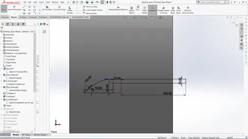
Fig 36: Sketch for axle on Rear Wheel
- Revolve the sketch about the 90mm line.
- Model a Disc brake rotor:
- Sketch a circle on the right plane of Ø 330mm.
- Extrude it offset 105mm and blind d1=7mm and don’t merge the result.
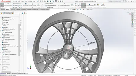
Fig 37: Sketch for disc brake rotor on Rear Wheel
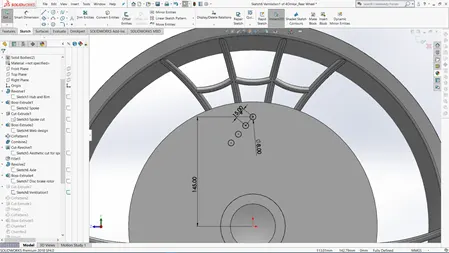
Fig38: Ventilation holes sketch for disc rotor of Rear Wheel
- Create sketch as shown for the ventilation holes 145mm vertical to the origin on the face of disc.
- Use circular sketch pattern with 16 instances about the disc centre and fully define the sketch.
- Extrude cut the sketches by using up to next.
- Create new sketch on the same disc face for slot cuts.
- Sketch 2 circles about the origin with Ø 90mm and Ø 210mm.
- Sketch a line vertical to the origin to connect both circles.
- Sketch another line connecting both the circles 25° apart from the previous line.
- Trim the outer sketches as shown in fig39.
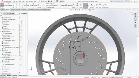
Fig39: Ventilation slot sketch for disc rotor of Rear Wheel
- Extrude cut the sketch up to next.
- Provide fillets to the sharp edges of 5mm.
- Use circular pattern with 9 instances about the rotor centre.
- Model the calliper for the disc brake:
- Sketch on the rotor face 2 circles of Ø 180mm and Ø 360mm.
- Sketch a vertical construction line from the centre of rotor above.
- Sketch 2 lines intersecting both circles keeping the lines 54° apart.
- Dimension an angle of 63° between the construction line and the solid line and trim the extras as shown in figure 25.
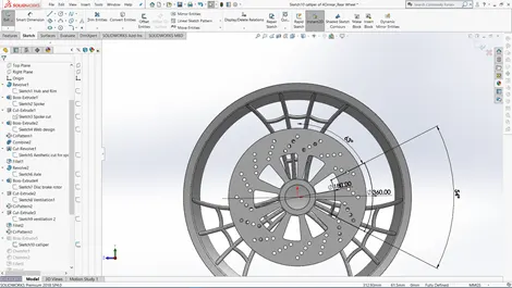
Fig40: Calliper sketch for Rear Wheel
- Extrude the calliper sketch from offset 3.5mm and midplane 30mm and do not merge results.
- Chamfer both faces of calliper (distance-distance with d1=6mm and d2=20mm).
- Fillet the edges with appropriate dimensions.
- Model the Sprocket:
- Sketch a Ø300mm circle on rear face of the axle.
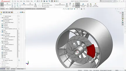
Fig41: Sprocket sketch for Rear Wheel
- Extrude 15mm blind from the axle face.
- Chamfer the face 1 of sprocket (angle-distance with angle of 45° and d=4mm).
- Sketch on the sprocket face as shown in fig42.
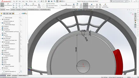
Fig42: Sprocket cut sketch for Rear Wheel
- Extrude cut the sketch up to next and provide 2.5mm fillet at sharp edges.
- Use Circular pattern for the cut about the centre of the sprocket with 61 instances.
- Sketch 2 circles of Ø 90mm and Ø255mm about the centre of sprocket face.
- Sketch a circle of Ø203mm and place it 35mm above origin and 50mm right of origin as shown in fig43.
- Place 2 arcs intersecting the circles and 12mm apart
- Trim extras as per fig43.
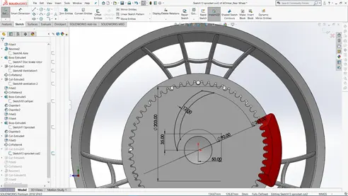
Fig43: Sprocket cut2 sketch for Rear Wheel
- Extrude cut the sketch up to next.
- Sketch 2 circles of Ø172mm and Ø255mm about the centre of sprocket face.
- Sketch a circle of Ø135mm and place its centre 35mm above origin and 50mm right of origin as shown in fig44.
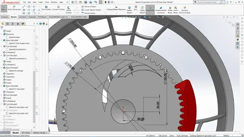
Fig44: Sprocket cut2 sketch for Rear Wheel
- Place 2 arcs 12mm apart and intersecting both circles.
- Trim the extras as in fig44.
- Extrude cut the sketch up to next.
- Create fillets at sharp edges with appropriate dimension.
- Use circular pattern of 6 instances for the 2 cuts created about the centre of sprocket.
- Model the tyre of rear wheel:
- Sketch on the Front plane and convert entities with intersection curve and delete the bottom instance that is converted.
- Sketch a 3-point arc of R366mm keeping the end points of arc horizontal and at a distance of 354mm.
- Centre of the arc should be horizontal to the origin.
- Keep vertical distance between origin and arc end point as 303mm.
- Sketch lines to connect the end points of arc to the converted entity on top of the rim.
- Use sketch fillet of 7mm at corner points as shown in fig45.
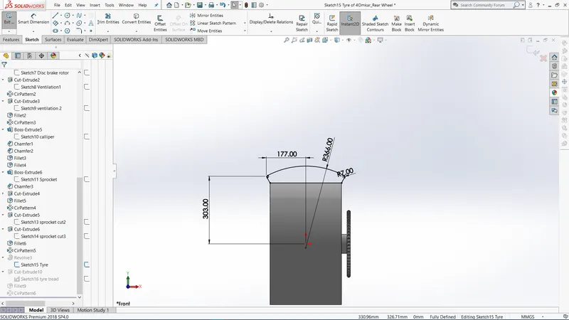
Fig45: Tyre sketch of Rear Wheel
- Revolve the sketch about the Right plane centre axis line and do not merge results.
- Tyre treads sketch:
- Sketch on Front plane 2x 3-point centre rectangle of dimension 280mm x 8mm.
- Sketch 2 more rectangles of dimension 97mm x 8mm.
- Sketch rectangle of 170mm x 8mm perpendicular to the left tread as shown in fig46. 30mm from end point of the rectangle.
- Place another rectangle on right treads of dimension 158mm x 8mm perpendicular and 30mm from end point of rectangle.
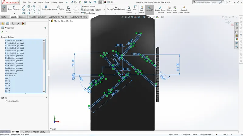
Fig46: Tyre sketch of Rear Wheel
- Extrude cut the entire sketch offset 400mm and use offset from surface of tyre face 6mm. Reverse the feature if cut preview not visible.
- See the preview for appropriate cuts.
- Keep the feature scope to the tyre only.
- Use Round fillets on the tread edges to make it look smooth.
- Use circular pattern for the tread cuts around the centre of tyre/hub with 10 instances.
- Apply the following appearances:
- Candy red apple car paint for calliper
- Chromium plate for rims and spokes with cob web design.
- Chromium plate for Disc brake rotor and Sprocket.
- Matte rubber for the tyre.
- Save the part as Rear wheel.
- Front Forks:
Front Fork is the component that helps in manoeuvrability of the motorcycle. Its efficient design helps in better ride and handling of the motorcycle. It also houses various sub components such as headlights, handle bars, handle grip, Triple clamps, Brake lever, clutch lever, cables and axle. It consists of front suspension component which is generally called telescopic forks. It is a 2-piece unit with hollow tube consisting of suspension oil and another piece a solid one which compresses the oil while tackling a bump or rough road surface.
The front forks of this American Chopper motorcycle has a high rake angle of 59° and a trail of nearly 650mm as in figure 47.
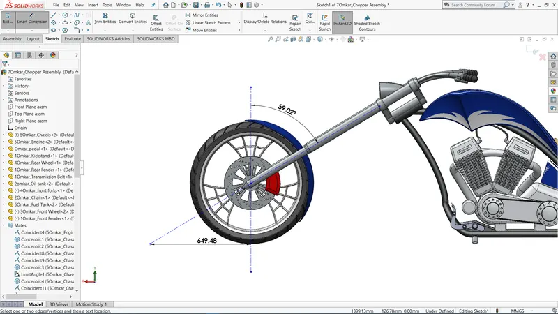
Fig47: Rake angle and Trail of the chopper
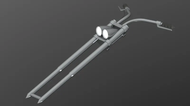
Fig48: Part Model of Front Forks
Tools Used:
Sketch tools:
- 3-Point arc
- Lines
- Splines
- Circle
- Trim
Features:
- Revolve boss/base
- Extrude boss/base
- Linear Pattern
- Extrude cut
- Revolve cut
- Dome
- Body move/copy
- Curves-Projected
- Sweep
- Reference geometry- planes
- Mirror
- Combine
- Fillet
- Chamfer
- Appearance
Procedure for modelling:
- Sketch the following on front plane
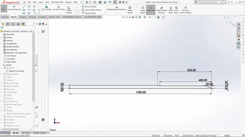
Fig49: Front plane sketch of Front Forks
- Revolve it about the 1330mm line.
- Sketch on top face of R30mm of fork and sketch a circle of Ø75mm.
- Create the sketch as shown in figure 49 to create triple clamp.
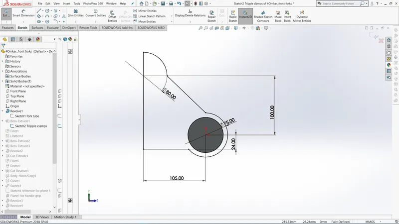
Fig49: Triple clamp sketch of Front Forks
- Extrude boss/base the sketch from offset towards the fork 20mm and d=40mm and do not merge results.
- Fillet all edges 5mm.
- Show temporary axis and use linear pattern for the triple clamp with 2 instances at 240mm distance.
- Create following sketch fig50 for the axle and extrude (up to surface select triple clamp flat surface)
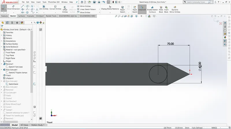
Fig50: Axle sketch of Front Forks
- Merge only with fork.
- Create a connection between triple clamps by sketch shown in fig52
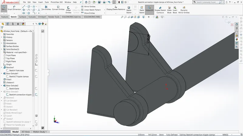
Fig52: Connection of triple clamp sketch of Front Forks
- Extrude it up to the upper triple clamp surface.
- Headlight Bucket sketch:
- Sketch as in fig53 on Front plane
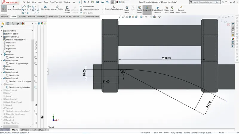
Fig53: Headlight Bucket sketch of Front Forks
- Revolve it about the line and do not merge.
- Move the bucket in Z direction -48mm.
- Make headlight detailing by extrude cut 5mm on face and using sketches as in figure 54 and use revolve cut.
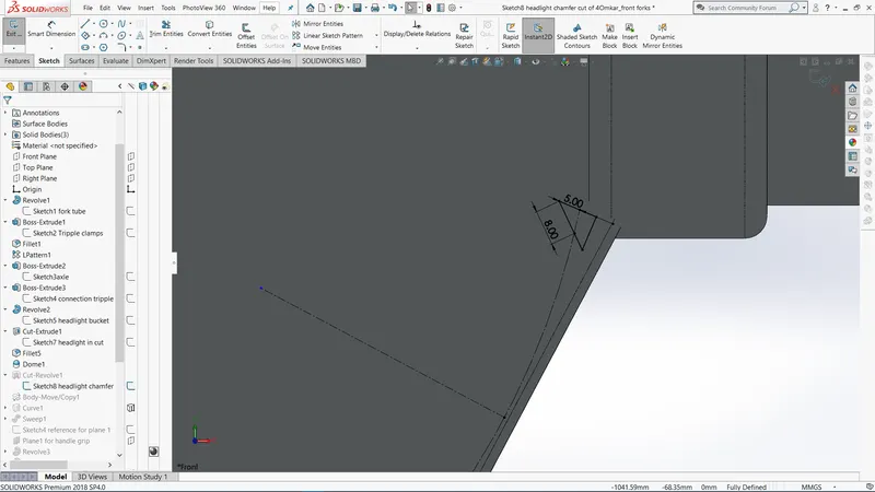
Fig54: Headlight detailing sketch of Front Forks
- Create a dome on headlight lens of 7mm.
- Handle bar sketch:
- Sketch a Ø35mm circle on face of triple clamp.
- Sketch on top plane as shown in fig55
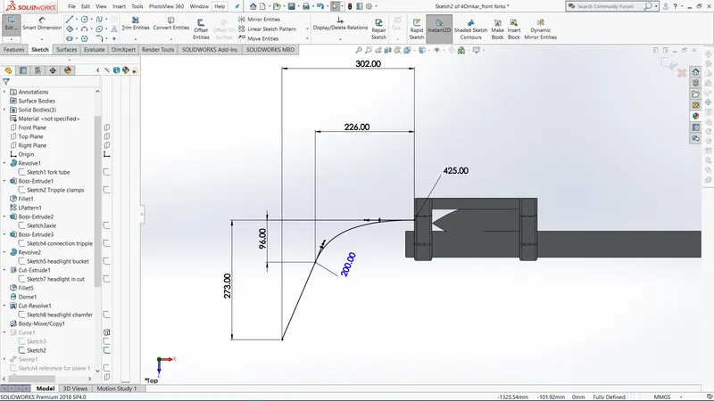
Fig55: Curve 1 sketch on top plane of Front Forks
- Sketch on front plane as shown in fig 56.
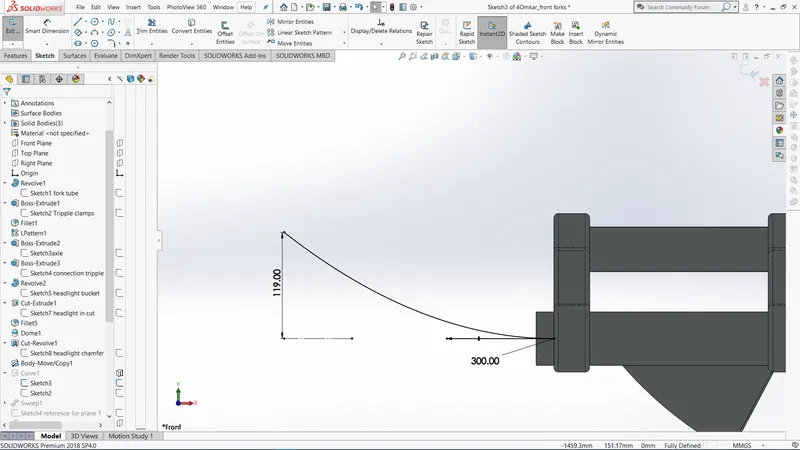
Fig56: Curve 1 sketch on top plane of Front Forks
- Use curves- Projected curves and create a curve from above 2 sketches.
- Sweep the circle on the curve path.
- Create handle grip on reference plane at handle bar end by sketch shown in fig 57.
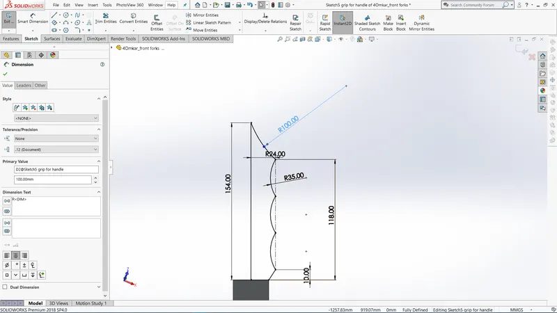
Fig57: Handle grip sketch of Front Forks
- Revolve the sketch about the 154mm line and merge with clamps only.
- Brake lever sketch:
- Create a new plane with plane 1 as reference at an angle of 160°.
- Sketch on this plane 2 as shown in Fig 58.
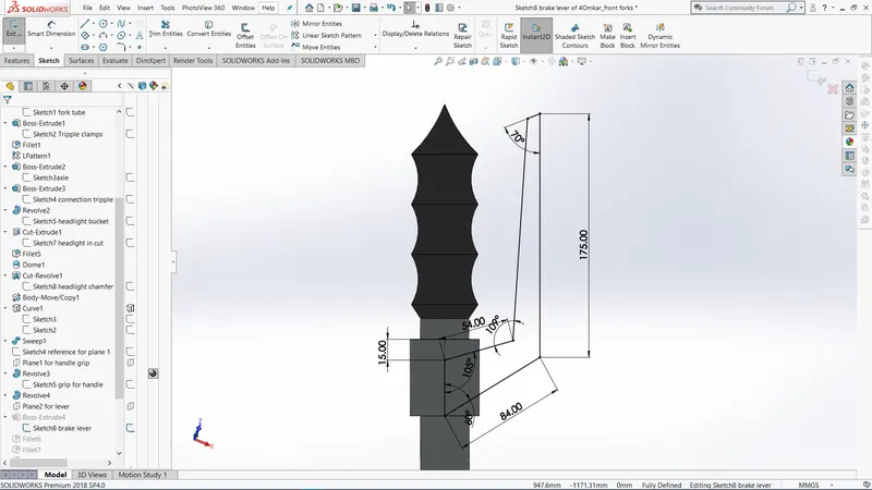
Fig58: Brake lever sketch of Front Forks
- Extrude the sketch midplane with d1=15mm.
- Fillet the edges appropriately.
- Create 2 sketches for cable and use projected curves.
- Mirror the whole front fork about flat face of triple clamp and combine the bodies.
- Apply following appearances:
- Chrome plate to headlight buckets, forks, triple clamp and handle bar.
- Glossy rubber on handle grips and cables.
- White area lights to the headlight face with luminous intensity of 1W/srm2
- Chassis:
Chassis is the main strength component or the structural framework of any automobile. All components of the motorcycle are either directly or indirectly mounted to the chassis. The chassis has to be the strongest component of any vehicle as it is the base structure. The chassis should be made up of high strength material that can withstand variable compressive, tensile and shear stresses.
The chassis used in this American chopper motorcycle is a rigid hardtail frame chassis which excludes the rear suspension component.
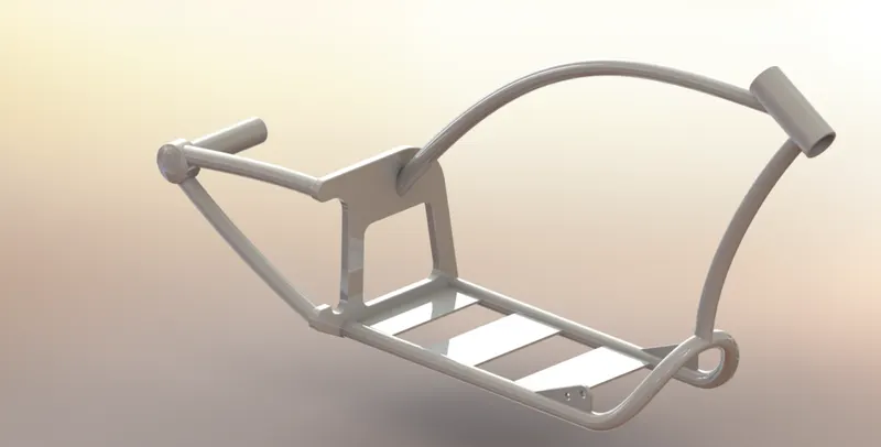
Fig59: Part Model of Chassis
Tools Used:
Sketch tools:
- Sketch Picture
- Lines
- Splines
- Circle
- Trim
Features:
- Extrude boss/base
- Extrude cut
- Revolve
- Dome
- Curves-Projected
- Sweep
- Split
- Reference geometry- planes
- Mirror
- Combine
- Fillet
- Chamfer
- Appearance
Procedure for modelling:
- Rename Top plane and Front plane to Bottom plane chassis and Midplane chassis respectively.
- Sketch on mid plane chassis and bring in the sketch picture of the chopper.
- Place the sketch picture by applying coordinates as x = -930mm and y = -805mm. Use transparency as required.
- Sketch on midplane chassis taking a reference of the sketch picture draw splines and sweep the splines with hollow tubes of Ø40mm and offset 4mm inwards to create concentric circles.
- Use Projected curves for chassis tubes in 3D as in sketch picture.
- Create sketch for Chassis back plate on right plane as in fig60.
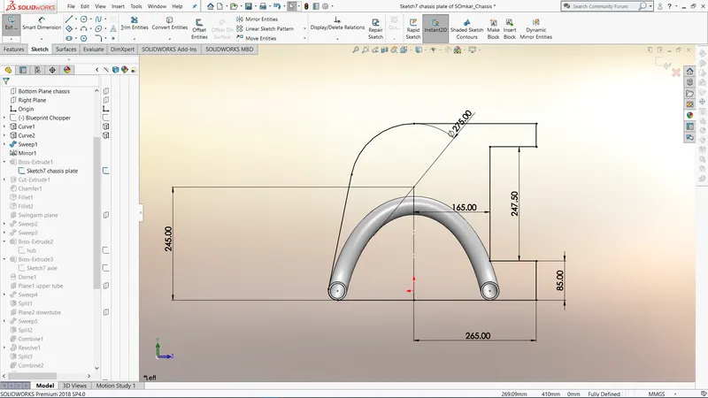
Fig60: Back plate sketch on right plane of Chassis
- Extrude boss the sketch 22mm away from tube section and merge results.
- Extrude cut the portion on back plate as per chassis shown in fig59.
- Sweep the swingarms on a new reference plane and create hub, axle and dome on hub.
- Create a new reference plane and Sketch as shown in fig61 for upper tube of chassis.
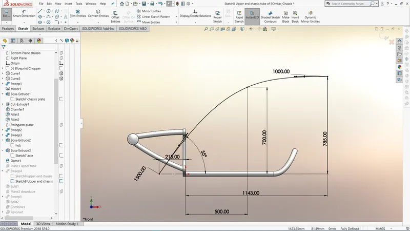
Fig61: Upper tube sketch of Chassis
- Sweep the sketch with similar tube sections as before.
- Use split and consume the bodies after the back-plate section.
- Create another reference plane for the downtube and create splines as per sketch picture and sweep the path using pierce relation.
- Use split at intersection of downtube to lower chassis and consume cut bodies.
- Create the sketch as in fig62 for steering stem.
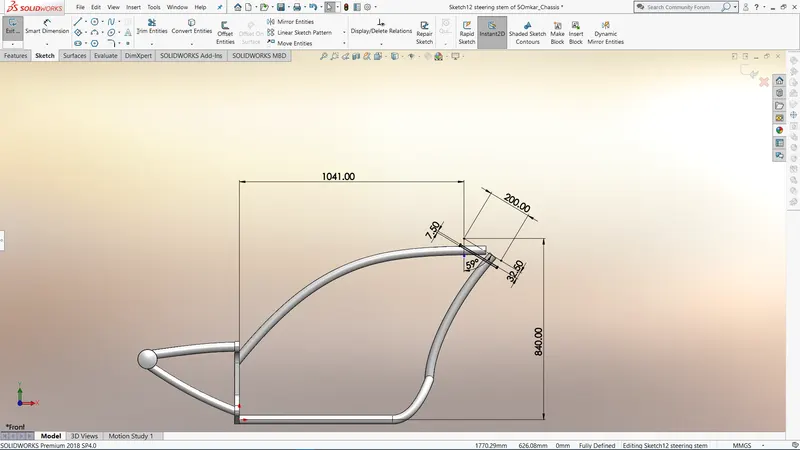
Fig62: Steering stem sketch of Chassis
- Revolve about the construction line and use split to consume bodies at intersection.
- Sketch as shown in fig63 for creating the chassis base plates.
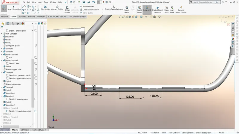
Fig63: Base plates sketch of Chassis
- Extrude the sketches up to next.
- Creating mounts for foot peg and kickstand is shown in fig 64 and 65.
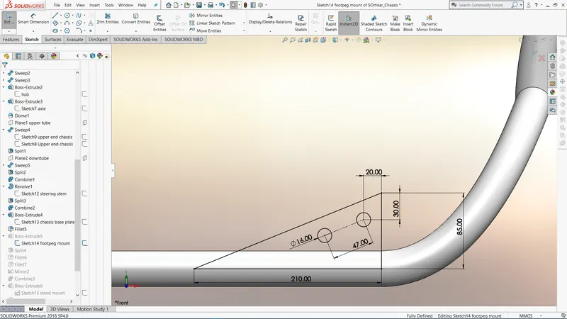
Fig64: Foot peg mount sketch of Chassis
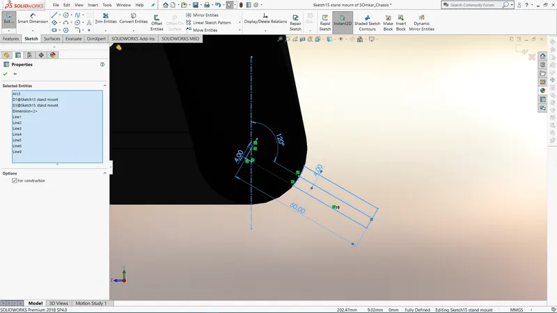
Fig65: Kickstand mount sketch of Chassis
- Use extrude boss, extrude cut and appropriate fillets for the mounts and mirror the foot peg mount about midplane chassis.
- Combine all solid bodies into one as chassis.
- Create a reference plane as bottom plane fuel tank 308mm above the bottom plane chassis.
- Apply black appearance from painted-car and save the part.
- Engine:
Engine is the main powerhouse of any automobile. Motorcycle engines are generally Internal combustion Spark ignition type. The engine consists of piston-cylinder arrangement which powers the motorcycle. The IC engine houses air intake, exhaust outlet and fuel intake ports.
This American chopper motorcycle has a V-Twin type engine consisting of external air filter, spark plugs 1 for each cylinder, transmission pulleys, air cooling fins, starter motor, front sprocket for chain drive, exhaust pipes and casing for sump and gearbox.
It also consists of 4 mounting points to the chassis.
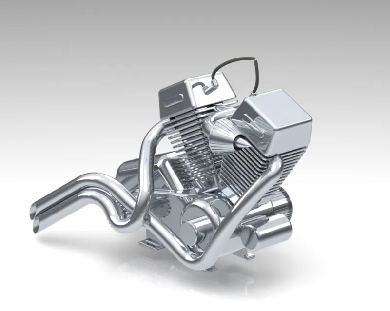
Fig66: Part Model of Engine
Tools Used:
Sketch tools:
- Sketch Picture
- Lines
- Splines
- Circle
- Circular sketch pattern
- Construction line
- Centre point rectangle
- 3-point centre rectangle
- Trim
Features:
- Extrude boss/base
- Extrude cut
- Revolve
- Dome
- Curves-Projected
- Composite curves
- Sweep
- Split
- Reference geometry- planes
- Circular pattern
- Linear Pattern
- Mirror
- Combine
- Fillet
- Chamfer
- Appearance
Procedure for modelling:
- Import the sketch picture of chopper and place on front plane with x=-1493mm and y=-965mm. Use appropriate transparency.
- Sketch using the picture reference on front plane the base of engine.
- Extrude the base 200mm midplane and the gearbox section 150mm midplane.
- Use fillets on sharp edges.
- Sketch the transmission belt pulleys on right plane as shown in fig 67.
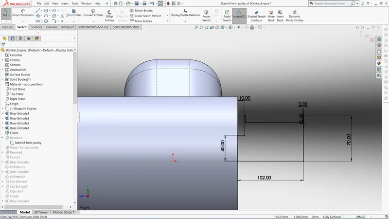
Fig67: Pulley sketch of Engine
- Revolve the sketch and make extruded rectangles on the pulley for grip element for belt, use circular pattern.
- Make circular pattern holes on pulley face and apply dome
- Do similar operations for rear pulley.
- Sketch for starter motor with the picture reference and extrude it appropriately.
- Sketch for cylinder casing using reference plane is shown in fig68
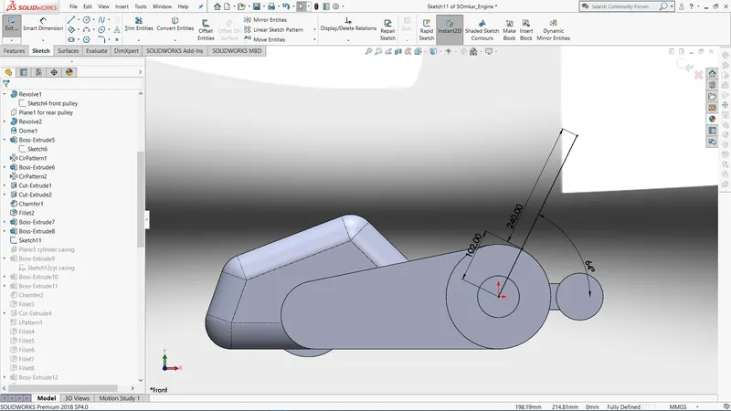
Fig68: Cylinder casing centre line sketch of Engine
- Sketch a rectangle on the plane and extrude it as per sketch reference.
- Provide fins using linear pattern and fillet as required.
- Create spark plugs and provide fillets.
- Mirror across the right plane to create second cylinder casing.
- Create mounts on bottom for the chassis mounts as in fig69.
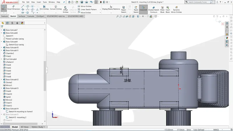
Fig69: Chassis mounts sketch of Engine
- Front Sprocket: Sketch Ø40mm at sprocket reference from the picture.
- Extrude the sketch 80mm and sketch sprocket circle and extrude further 15mm.
- Provide chamfer, chain cuts as done with rear sprocket as in fig70.
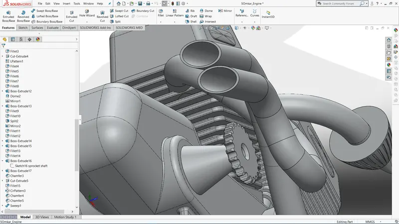
Fig70: Front sprocket of Engine
- Provide chamfer to the sprocket shaft as in fig70.
- Exhaust pipes: Use spline following the sketch picture and use projected curves.
- Sketch a line to cut out the exhaust ends using split.
- Use splines and projected curves for air intake manifold.
- Sketch the air filter and revolve it and provide cuts using extrude cuts.
- Use splines and sweep it with circles for the spark plug cables.
- Provide polished Aluminium appearance to the engine and gloss black to spark plugs and the cables and save the part as engine.
- Fuel Tank:
Fuel tank is the fuel storage component of the motorcycle. It is made to store flammable fluids or gas in a cool state away from the engine heat. Safety of the petrol is the main criteria in designing the fuel tank. It is connected to a fuel pump or a fuel regulator device such as carburettor or an injection system to supply appropriate amount to the engine with proper mixture of air and fuel.
The fuel tank of this American chopper is made to house a seat and fit to the chassis centrally with the mount. It is made up of surfaces and finally these surfaces are knit together to form a complete solid body with hollow shell to store fuel.
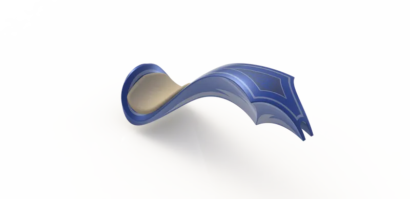
Fig71: Part Model of Fuel Tank
Tools Used:
Sketch tools:
- Sketch Picture
- Lines
- Splines
- Construction line
- Trim
Features:
- Surface sweep
- Surface loft
- Surface trim
- Boundary Surface
- Surface knit
- Surface Extrude
- Curves
- Projected curves
- Split line
- Sweep cut
- Reference geometry- planes
- Mirror
- Shell
- Fillet
- Appearance
Procedure for modelling:
- Rename the Front, Top and Right planes to Mid plane FT, Bottom plane FT and Right plane FT respectively.
- Bring in sketch picture to Mid plane FT and place it x=-2096mm y=-1096mm and use appropriate transparency.
- Sketch on mid plane FT as in fig 72
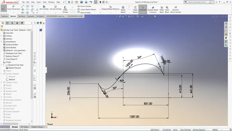
Fig72: Mid plane sketch of Fuel Tank
- Create new reference plane using front plane on the starting point of the sketch of fig72.
- Create appropriate splines on new plane using the picture reference.
- In surface tab use sweep in direction of Mid plane FT.
- Sketch splines on Bottom plane FT as in fig73 using the picture reference.
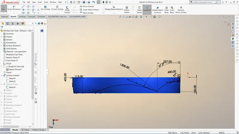
Fig73: Bottom plane sketch of Fuel Tank
- Create projected curves, new planes and sketch as in reference picture.
- Use surface loft for the new sketches.
- Use boundary surfaces and appropriate relations to create the surface model of fuel tank.
- Create sketch for the seat on the bottom plane ft as in Fig 74.
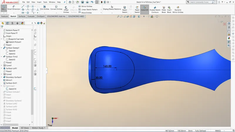
Fig74: Seat sketch on Bottom plane of Fuel Tank
- Use surface extrude for the seat and provide appropriate fillets.
- Knit all surfaces and make solid.
- Create a shell of 3mm without any selection.
- Give appearance to seat as beige cotton fabric and the fuel tank as painted car blue.
- Save the part.
Assembly
American Chopper Motorcycle Assembly:
The assembly of the chopper consists of all the parts attached in appropriate manner with proper mates. The main component chassis is first fixed and other parts are mated with respect to its position.
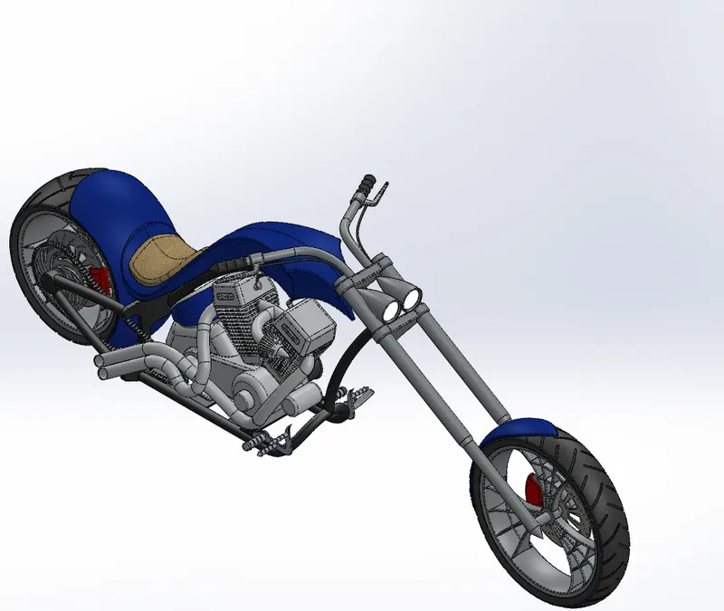
Fig75: Assembly of American Chopper Motorcycle
Mates in assembly:
Mates in assembly environment is analogous to relations in part environment. Basically, it is the relation between two different components. Solidworks assembly mates consists of 3 main mates namely Standard mates, Advanced mates and Mechanical mates.
Standard mates consist of: Coincident, Concentric, Parallel, Perpendicular, Tangent, Lock, Mate alignment angles and distance mates.
Advanced mates consist of Profile centre, Symmetric, Path mate, Width mate, Linear/Linear coupler, Angle and distance mates.
Mechanical mates consist of Cam, Slot, Hinge, Gear, Rack & Pinion, Screw, Universal joint.
The analysis tab under mates is used to define motion analysis between two components.
The mates applied to the chopper assembly are shown in figure below:
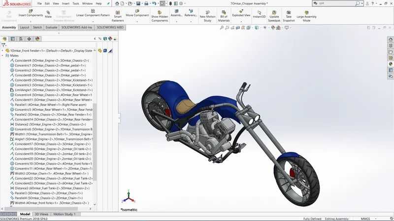
Fig76: Assembly mates of American Chopper Motorcycle
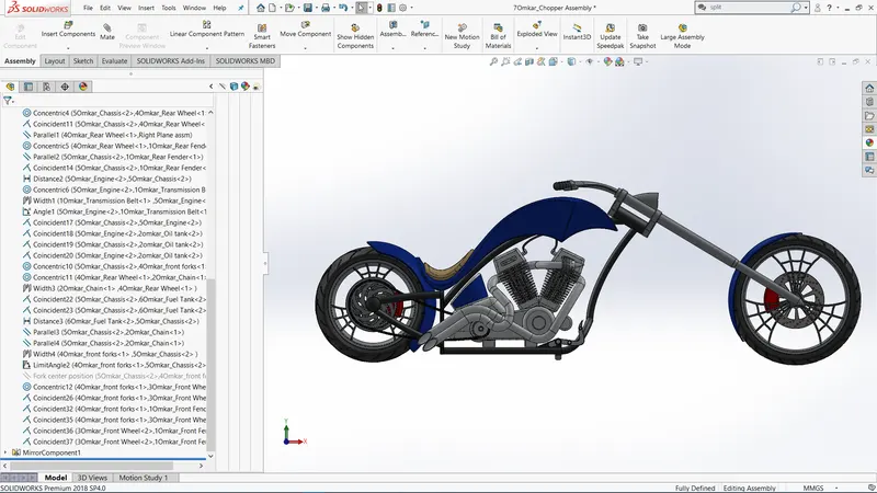
Fig77: Assembly mates of American Chopper Motorcycle
Procedure for Assembly:
- Fix the chassis position on the Front plane of the assembly coincident to mid plane chassis.
- Give relation coincident Mid plane chassis and front plane engine.
- Make the engine mounts coincident to the base plate of chassis and 20mm behind the vertical face of plate.
- Make the pedals concentric and coincident to the mounts and mirror the part appropriately.
- Use coincident, concentric and limit angle mates with kickstand and mount.
- Give relation coincident Mid plane chassis and Right plane rear wheel and make the axle hole concentric to the Hub axle on swingarm.
- Give relation parallel to right plane chassis and front plane of rear wheel.
- Make rear fender concentric to rear wheel and give relation parallel to vertical plane Rear Fender and Right plane chassis.
- Give relation coincident to mid plane chassis and mid plane rear fender.
- Give width mates, concentric and angle mates to transmission belt on pulleys.
- Make oil tank coincident on gearbox face and give relation of coincident to Midplane chassis and mid plane of oil tank.
- Back edge of oil tank coincident to the edge of gearbox.
- Make front forks concentric to the steering stem and give width mates on the chassis, limit the rotation to 30° in both directions.
- Make a central position mate and suppress it.
- Use concentric and width mates for the chain with rear wheel, make its front centre coincident to the front sprocket sketch or apply appropriate angle mates if error occurs.
- Give parallel relations between midplane chain and midplane chassis; parallel relation between Bottom plane chassis and centre plane chain.
- Make bottom plane FT coincident to plane created in chassis.
- Make Midplane FT and Midplane Chassis coincident.
- Give a distance mate of 5mm for Front plane FT from plane 1 in chassis.
- Give relation coincident to Midplane forks and right plane front wheel.
- Make the axle concentric to axle hole.
- Use coincident relations to straighten the front wheel with respect to the front forks.
- Make the front wheel, rear wheel and the kickstand tangent to the top plane of the assembly to give it a rest position.
- Save the assembly.
- Photorealistic Rendering
Rendering of the assembly is done to make a good quality 2D images for the purpose of advertising and promotion of the products before selling it to the customers. Photorealistic rendering creates high quality images or motion graphics if available so as to look appealing in various environments and backdrops.
Solidworks provides 2 rendering products:
- Photoview 360 which is inbuilt add in for Solidworks
- Solidworks Visualize which is a separate Render Engine.
- Photoview 360:
- After adding photoview 360 the render tools tab can be brought in
- It has various options like preview window, render region, final render, edit appearance, edit scenes, and options for managing render quality, Bloom, cartoon, direct caustics, network rendering and final image type.
- Schedule render and recall last renders are also some options.
- Decals can be added using edit decals, image can be added on faces by mapping values in coordinate directions. Illumination can be set to underlying appearance for better blending of decals.
- Display states can be set for parts individually so as to provide multiple appearances to a single part and changing the appearance whenever required.
- From view dropdown- Lights and camera is for setting up camera views and lighting of the scenes.
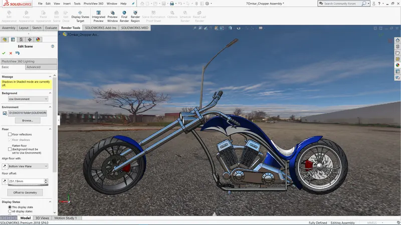
Fig78: Photoview 360 Environment
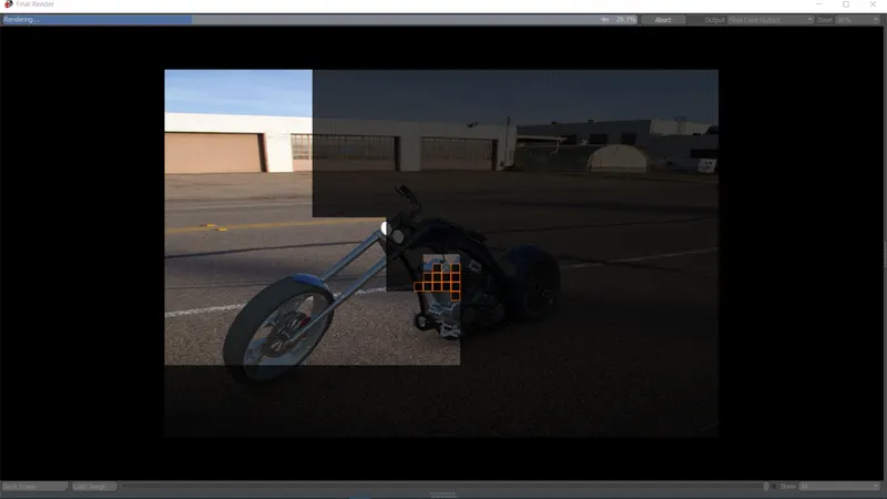
Fig79: Processing of final render in Photoview 360 Environment
- Some snapshots of photoview 360 rendered images are shown below:
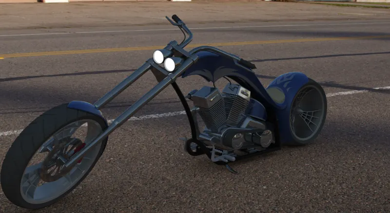
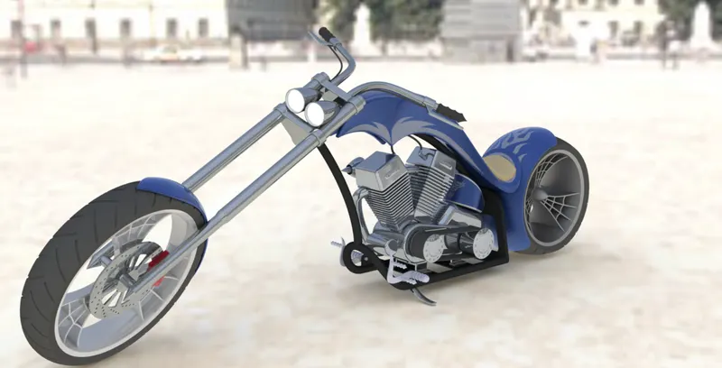
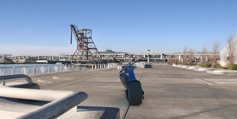
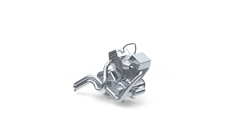
- Solidworks Visualize:
- Solidworks Visualize provides a suite of standalone software tools that combine industry-leading rendering capabilities with visual design-oriented features and workflows, allowing easy and fast creation of visual content that communicates a design’s vision, passion, and emotion.
- It is a separate render engine that is provided under solidworks professional.
- Visualize Professional adds an array of features including animations, custom lighting, VR, 360 Interactive, and much more.
- Solidworks Visualize Professional provides the highest level of detail and optimized render times.
- It helps in creating Rendered images of the solidworks models in Photorealistic environments for marketing quality images with various options to tweak on the final image required as per the user.
- It uses either of the CPU or GPU or both as hybrid to render quality images.
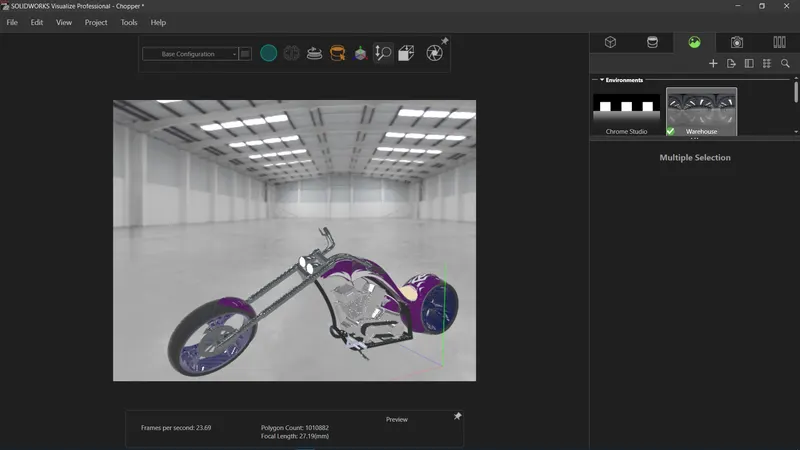
Fig80: Solidworks Visualize Environment
- Import the assembly and select part grouping as appearance, this ensures that all the parts having same appearance are grouped together in appearance tab.
- All parts having same appearance can be tweaked together using appearance options.
- Setting up of background can be done from scenes tab which includes a wide range of HDR images and backgrounds.
- Background brightness, rotation, gamma can be changes as required from the scenes tab.
- Camera views can be added or used from assembly.
- Render output image properties can be changed from output tools. Things such as image size, animation, photograph scenes, usage of CPU, GPU or both as hybrid can be selected.
- Some rendered images of chopper are attached below:
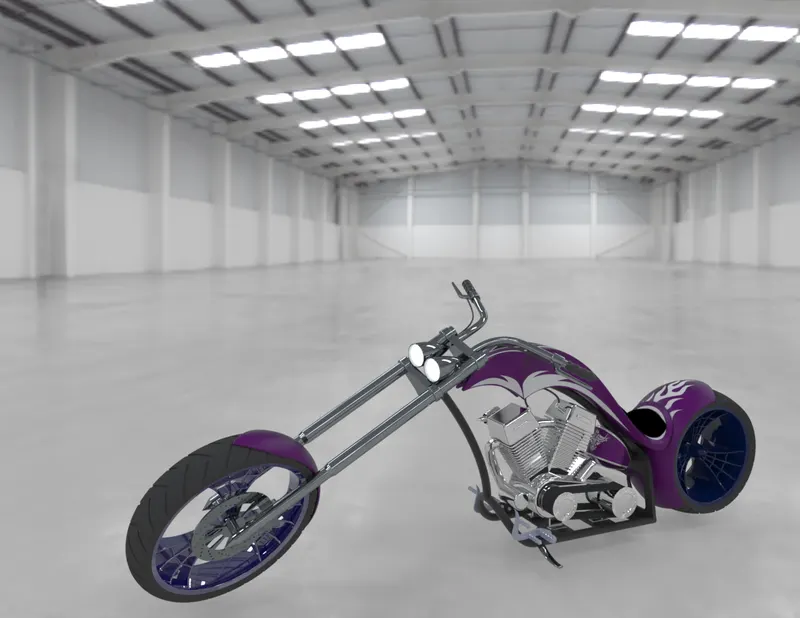
Fig81: Chopper inside a warehouse
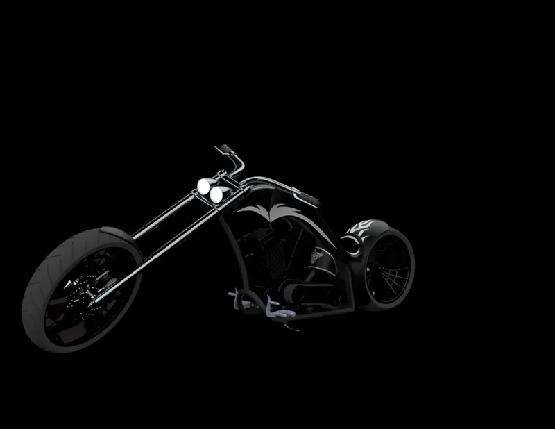
Fig82: Magazine advertising image of the chopper
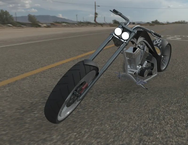
Fig83: Chopper at Route 66.
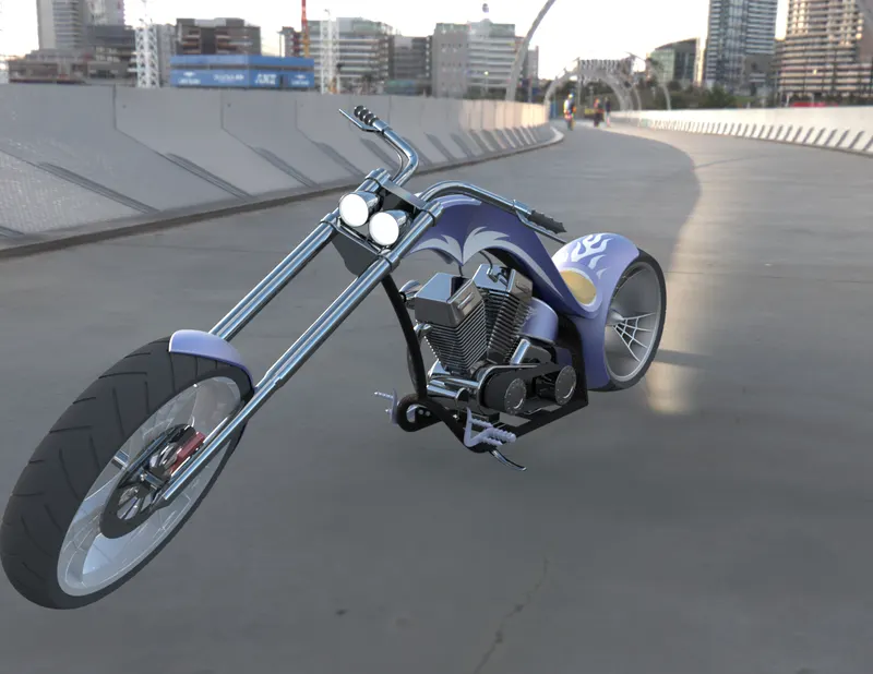
Fig84: Chopper on a bridge
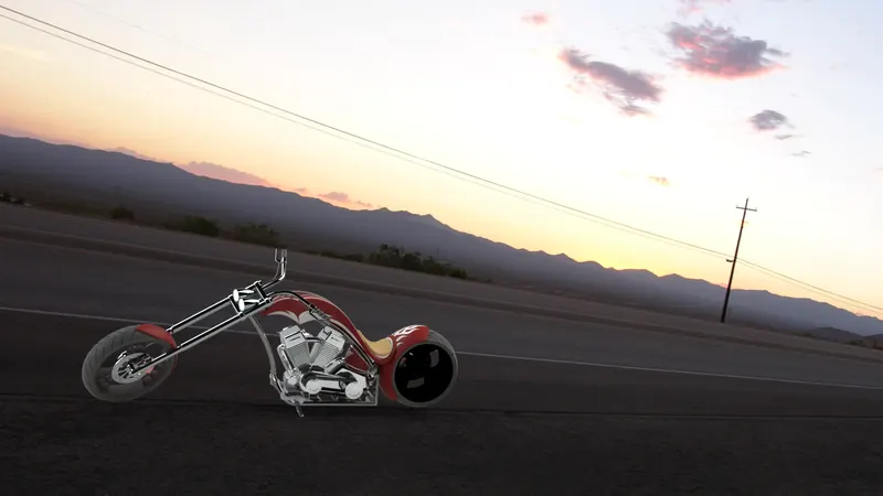
Fig85: Chopper in desert road during a sunset.
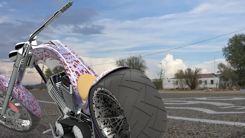
Fig86: Chopper rear bottom camera view at route 66.
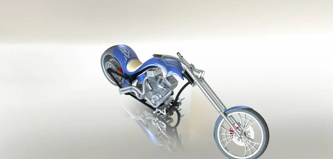
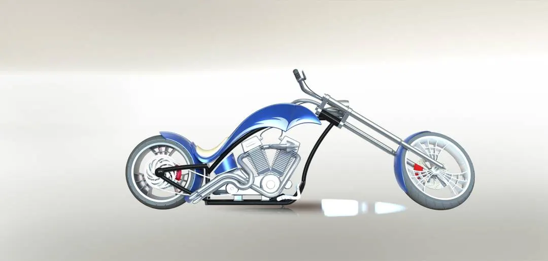
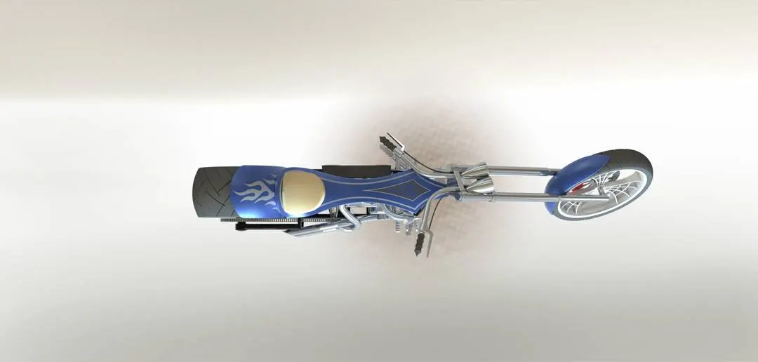
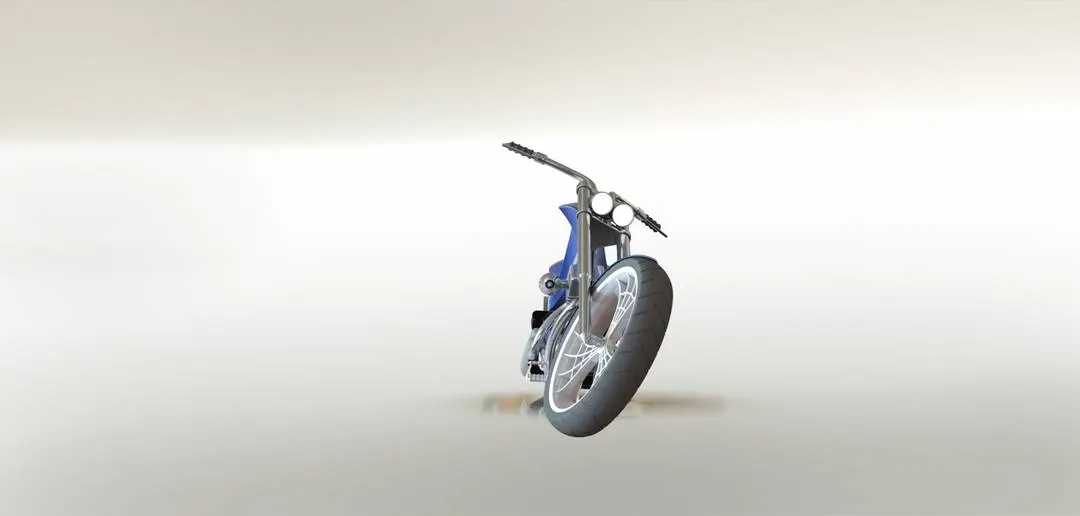
- The required views of rendered images are shown below:
- Isometric view
- Side view
- Top View
- Front View
Conclusion: Design, Assembly and Photorealistic rendering using Solidworks was successfully completed.