BOX ASSEMBLY - Advanced Sheet Metal Design using NX Cad
BOX ASSEMBLY USING NX CAD - SHEET METAL WORKBENCH
Objective:
- To learn and implement the principles of Advanced Sheet Metal design using NX CAD as a tool.
- To understand Sheet Metal applications and its importance as per industry standards.
Introduction:
Sheet metal is any metal that has a thickness in between 0.5 mm and 6 mm. Any metal piece thicker than 6mm are considered as Structural Metal (for ex. Structural Steel) and any metal piece having thickness lower than 0.2mm is called Metal Foil (for ex. Aluminium Foil).
Sheet metal is one of the fundamental forms used in metalworking, and it can be cut and bent into a variety of shapes. It is found in various industrial application ranging from small and light Fixture to an Automotive Body Part. Sheet metal applications have wide range due to its properties like: High Strength, Low weight and Corrosion Resistance.
General Sheet Metal materials are Steel, Aluminium, Brass, Titanium. There are 2 ways of producing Sheet Metal – Hot Rolling and Cold Rolling. For precision applications, cold rolled steels are preferred as manufacturers have more control over the final dimensions. This is because in hot rolled steels, after cooling, the steel shrinks slightly and the shape might change a little.
Sheet Metal Forming processes are as follows:
- Sheet metal Bending
- Sheet metal curling
- Sheet metal decambering
- Sheet metal expanding
- Deep Drawing
- Hydroforming
- Incremental Sheet Forming
- Ironing
- Laser Cutting
- Photochemical Machining
- Press Brake Forming
- Punching
- Rolling
- Wheeling
Sheet Metal Terminologies:
- Bend Radius: When a Sheet Metal is bent it does not exactly form exactly 90° at the corner. The corner is curved forming a Tangency between the web and the Leg forming a G1 continuity. The Inside Radius of this curved corner is called Bend Radius.
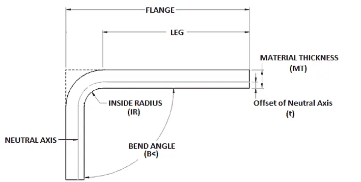
Figure1: Sheet Metal Bend Terms
- K-Factor: When a material is bent the Inner portion undergoes Compression and the Outer portion undergoes Tension. This changes the length of both inner and outer surfaces. There is a Neutral Plane between both these planes where change in length is Zero. This is where transition from Compression to Tension takes place.
- The Ratio of Neutral Line distance to the Material Thickness is called K-Factor.
- Value of K- Factor depends on 1. Material Thickness, 2. Material Properties and 3. Bend Radius.
- Y factor = 𝝅/2 * K-Factor
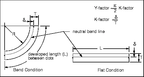
Figure2: K-Factor and Y-Factor of sheet metal.
- Bend Allowance and Bend Deduction: These two are the methods chosen to determine the flat length of sheet metal stock to give the desired dimension of the bent part. Other methods include Bend Tables, K-Factor and Bend calculation.
By definition, the bend allowance is the arc length of the bend as measured along the neutral axis of the material. By definition, the bend deduction is the difference between the bend allowance and twice the outside setback.
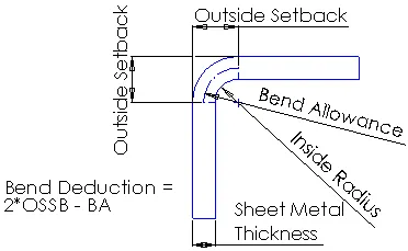
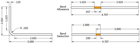
Figure3: Bend Allowance and Bend Deduction Illustration.
Design tool: Siemens NX
File extension for NX: (.prt)
NX, formerly known as "Unigraphics", is an advanced high-end CAD/CAM/CAE, which has been owned since 2007 by Siemens PLM Software. The version used in this Casing design is NX 12.
The key functions of NX are as follows
- Computer-aided design(CAD) (Design)
- Parametric solid modelling (feature-based and direct modelling[)
- Freeform surface modelling, class A surfaces.
- Reverse engineering
- Sheet metal design
- Assembly modelling
- Routing for electrical wiring and mechanical piping
- Computer-aided engineering(CAE) (Simulation)
- Stress analysis / finite element method (FEM)
- Kinematics
- Computational fluid dynamics (CFD) and thermal analysis
- Computer-aided manufacturing(CAM) (Manufacturing)
- Numerical control (NC) programming
Parts in this box Assembly:
- Box
- Lid
- Hinge between Lid and Box
- Lid opener (extra feature)
Design Methodology:
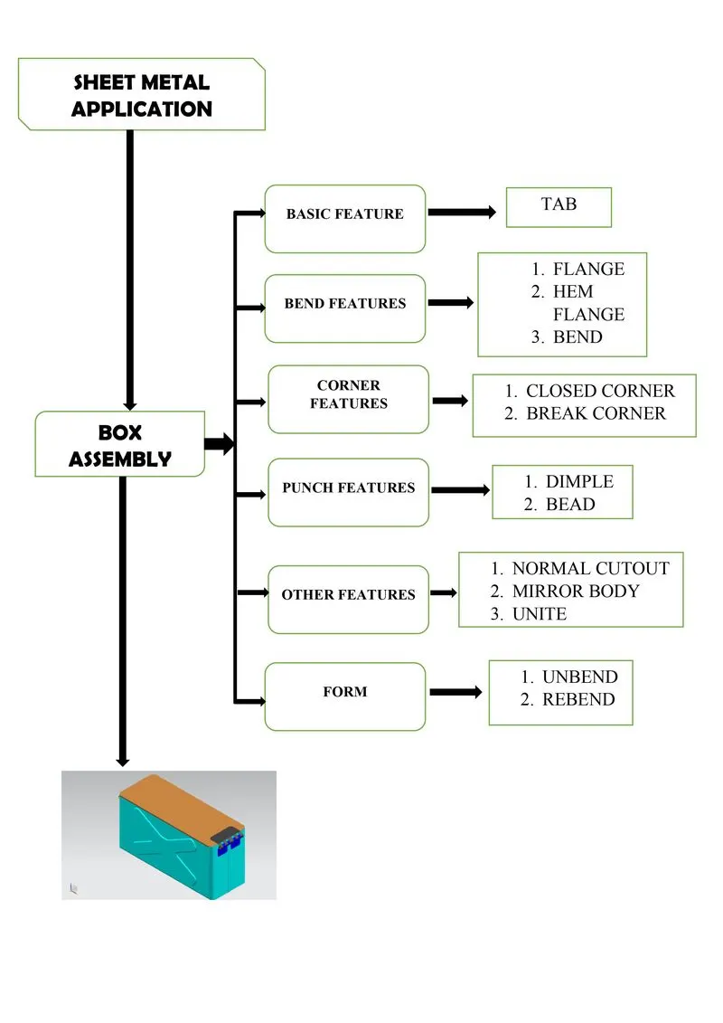
Description:
Box Assembly in NX Sheet metal Workbench
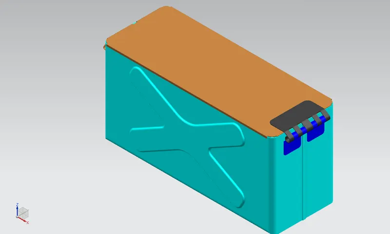
Figure4: Box Assembly
Sketch Tools Used:
- Profile
- Lines
- Circle
- Rectangle
- Project curve
Features Used:
- Tab
- As base feature
- As Secondary feature
- Flange
- Hem Flange
- Open type
- Closed type
- Open Loop type
- Closed Corner
- Dimple
- Bead
- Normal Cut-out
- Mirror Body
- Combine-Unite
- Unbend
- Rebend
Views of Box Assembly:
Isometric View:
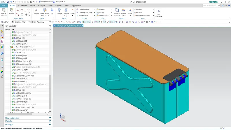
Front View:
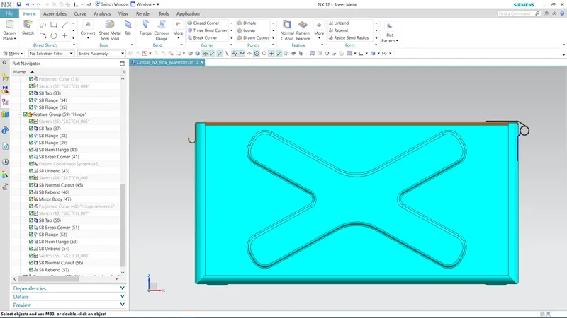
Left Hand Side View:
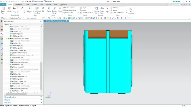
Right Hand Side View:
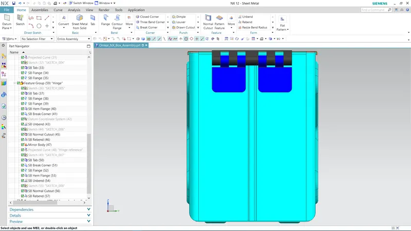
Top View:
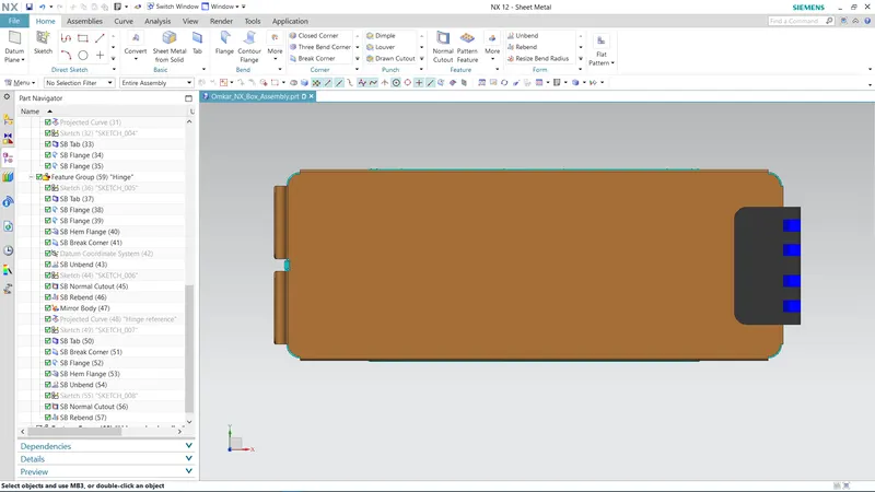
Bottom View:
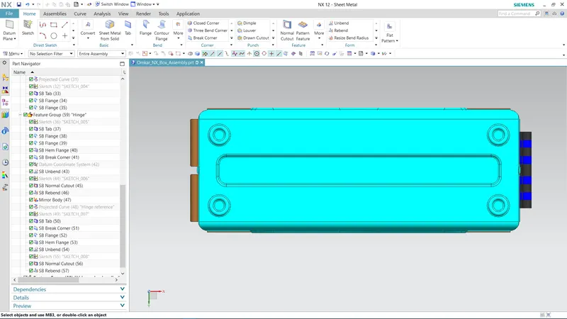
Conclusion:
The principles of Sheet metal design were practiced and understood while modelling of Box Assembly using various features and tools in NX CAD.