Design, Assembly and Rendering of Sunseeker Predator Yacht using Solidworks
Design, Assembly and Rendering of Sunseeker Predator Yacht using Solidworks
Objective:
The objective of this project is to understand and demonstrate the design philosophy of a Sunseeker Predator Yacht using design tool – Solidworks. In the design, assembly and the rendering phases, usage of sketch tools and making sure that it is fully defined, use of Surface and Solid Modelling, importance of Surface Continuity, importance of mates in assembly, usage of rendering tools in Photoview 360 as well as Solidworks Visualize is completely dealt with understood.
Introduction:
Sunseeker Predator Yacht:
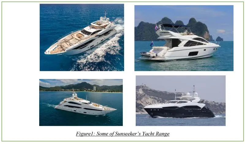
Sunseeker International is a British luxury performance motor yacht brand. Manufacturing is undertaken mainly in Poole, England in seven production plants and shipyards where it employs 2,600 people and produces around 150 boats every year ranging from 38-161 feet. An additional deep-water shipyard is used to build the 105 yacht and larger vessels. Poole is also home to Sunseeker's dedicated Design & Technology Centre, a unique facility which vertically integrates every detail of the yachts from the initial concept designs through to the finishing details including furniture, complex electrical systems, helm consoles and soft furnishings. As Sunseeker produces these components in its own dedicated facility, it is able to offer exceptionally high-quality control, craftmanship and attention to detail. Some of Sunseekers Yacht models are show in Figure1.
Design tool: Solidworks
SolidWorks is a solid modelling computer-aided design (CAD) and computer-aided engineering (CAE) program published by Dassault Systems. According to the publisher, over two million engineers and designers at more than 165,000 companies were using SolidWorks as of 2013.
Solidworks has three basic environments namely: Part, Assembly and Drawing. Each of which is further elaborated below.
Part modelling or 3D Solid / Surface modelling in Solidworks uses 2 approaches parametric modelling approach and feature based approach simultaneously, wherein parameters determine the shape and geometry of the solid model or the assembly. Parameters include numerical values such as lengths, diameter/radius as well as geometrical components like tangency, collinearity, parallel, concentricity, vertical, horizontal etc. Features determine the shape of the part/model as required by the user. Converting 2D sketches into 3D models requires the Feature based approach. Some features of Solidworks are extrude boss, extruded cut, revolve, revolve cut, shell, loft, sweep, hole, fillet, chamfer, slot etc.
Sketches in Solidworks include both 2D and 3D sketches. 2D sketches include splines, circles, rectangles, slots, arcs, lines etc. In 3D sketch a more complicated inter-planar curve or sketches can be created.
Using various terms from above a part/model can be created successfully.
Assembly of various parts can be done in the assembly environment. In this environment the Mates determine the final assembly and relation of various parts to each other. Mates are categorized into General, Advanced and mechanical mates. General mates determine the constraints between two parts such as concentricity, parallelism, coincidence, tangency whereas advanced mates can be used for mating chain and sprocket using width mate, gear mates for proper rotation of gears etc.
Drawing environment is mainly used to create 2D sheets with all main views of the solid parts and assembly. These sheets also include details used for manufacturing of the component such as geometric dimensions, tolerances and section views of the required part/assembly.
File Formats in Solidworks:
Parts: (. SLDPRT)
Assembly: (. SLDASM)
Drawing: (. SLDDRW). Solidworks also has products such as Photoview 360 for appearance, scenes and photorealistic renderings inside Solidworks environment and Solidworks Visualize which a Render engine for good quality image rendering.
Design methodology flowchart:
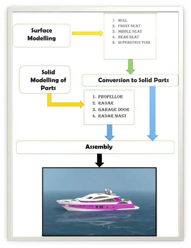
Figure2: Flowchart of Design Methodology of Yacht
DESCRIPTION:
Solid and Surface modelling; the sketch tools used and features used for the complete modelling of all the parts of the Yacht and its Assembly procedure is explained in this section briefly.
- Parts
- Propeller

Sketch tools used:
- Lines
- Splines
- Construction lines
- 3-point corner rectangle
Features Used:
- Revolve Boss/Base
- Solid Loft
- Extruded cut
- Fillets
- Circular pattern
Isometric View:
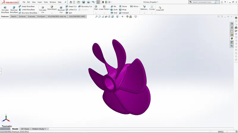
Figure3
Front view (with expanded feature tree):
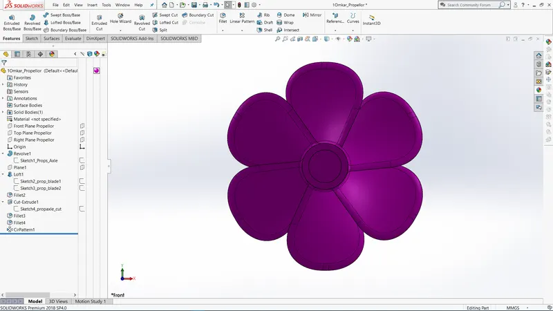
Figure4
Right hand side view:
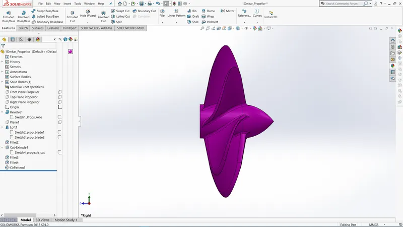
Figure5
- Radar
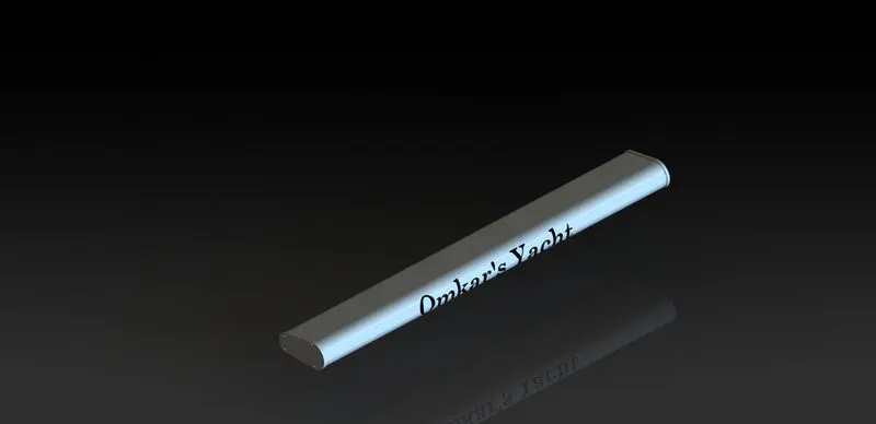
Sketch tools used:
- Line
- Sketch offset
- Circle
- Polygon
- Points
Features Used:
- Extrude Boss/Base
- Fillet
- Extruded cut
- Sketch Driven Pattern
- Mirror
- Split Line
Isometric View (with expanded feature tree):
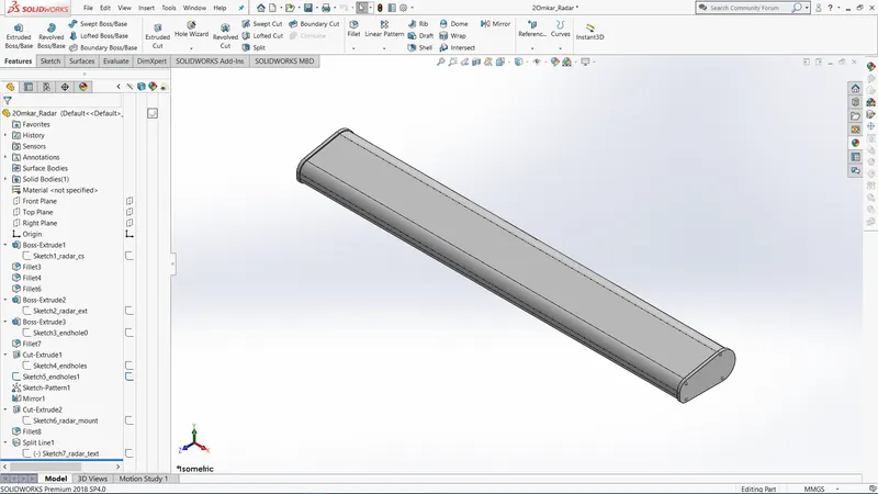
Figure6
Front/Back view:
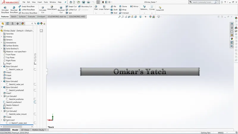
Figure7
Right hand side view:
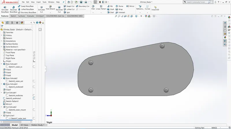
Figure8
- Blueprint Setup
Sketch tools used:
- Sketch Picture
Features Used:
- Reference Plane
Isometric View (with expanded feature tree):
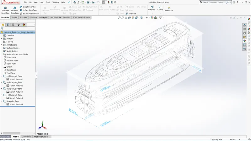
Figure9
Front view:
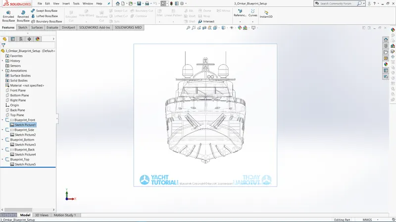
Figure10
Back view:
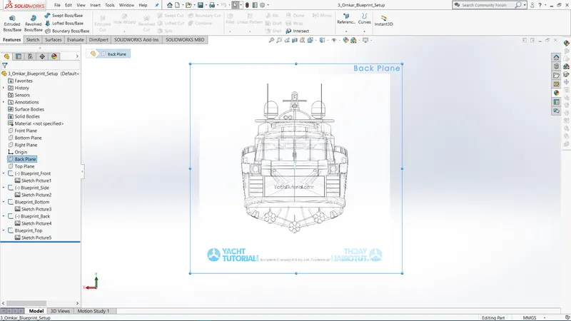
Figure11
Side view:
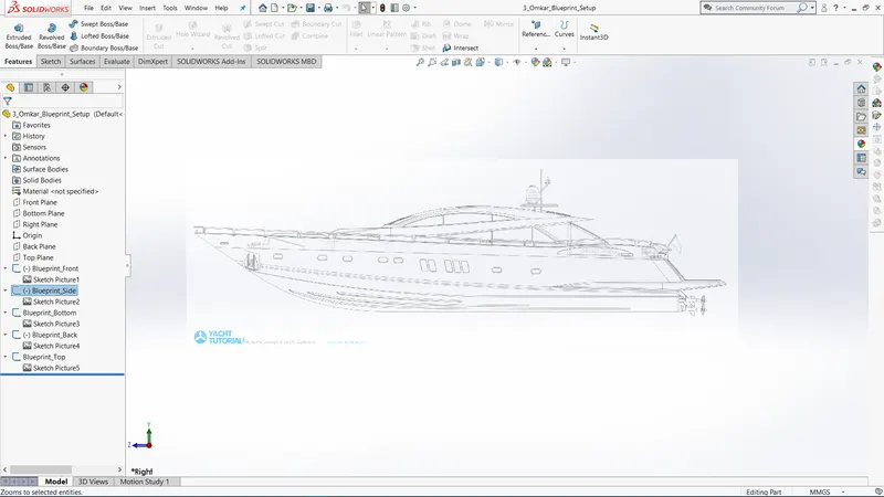
Figure12
Top view:
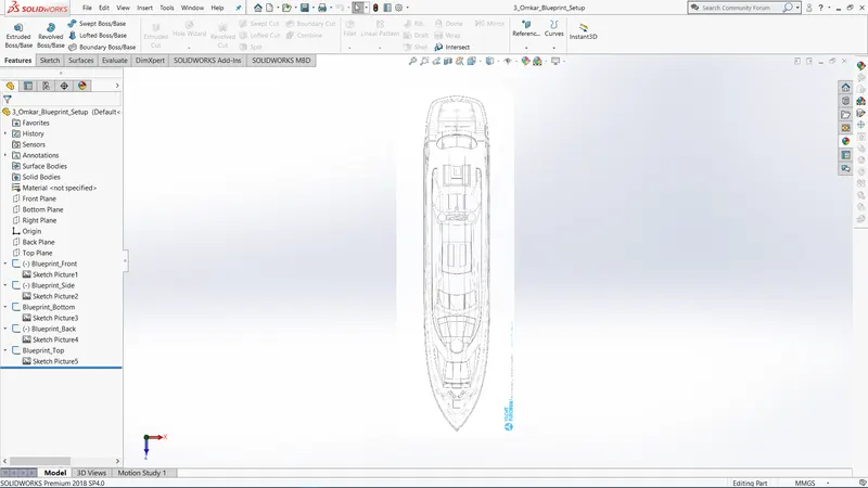
Figure13
Bottom view:
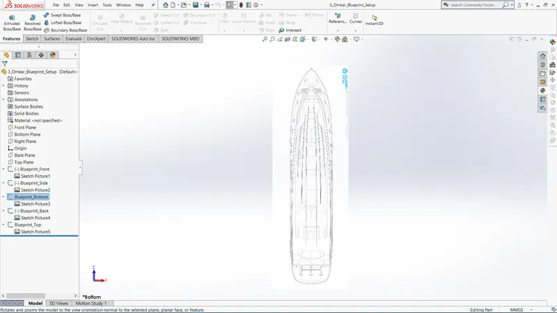
Figure14
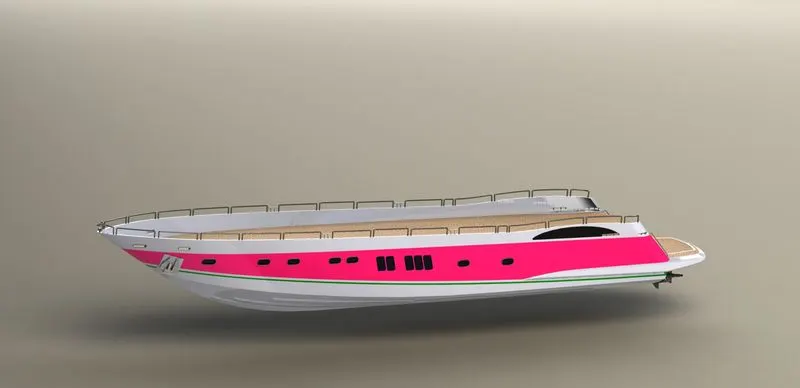
- Hull
Sketch tools used:
- Sketch pictures
- Lines
- Splines
- Construction lines
- Slots
- 3d sketch
- Circles
- Rectangles
- Ellipse
- Convert Entities
- Offset Entities
- Trim tool- power trim
- Extend
- Mirror
- Linear sketch Pattern
Features Used:
- Projected curves
- Reference planes
- Surface loft
- Surface Trim
- Surface Extrude
- Surface Knit
- Surface Fill
- Shell
- Extruded boss/base
- Extruded cut
- Fillets
- Chamfer
- Swept boss/base
- Helix and spiral
- Linear Pattern
- Mirror
- Revolve boss/base
- Delete face
- Extrude thin
- Save bodies
- Split Line
- Combine
- Decals and appearances.
Isometric view (with expanded feature tree):
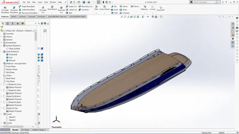
Figure15
Top view (with expanded feature tree):
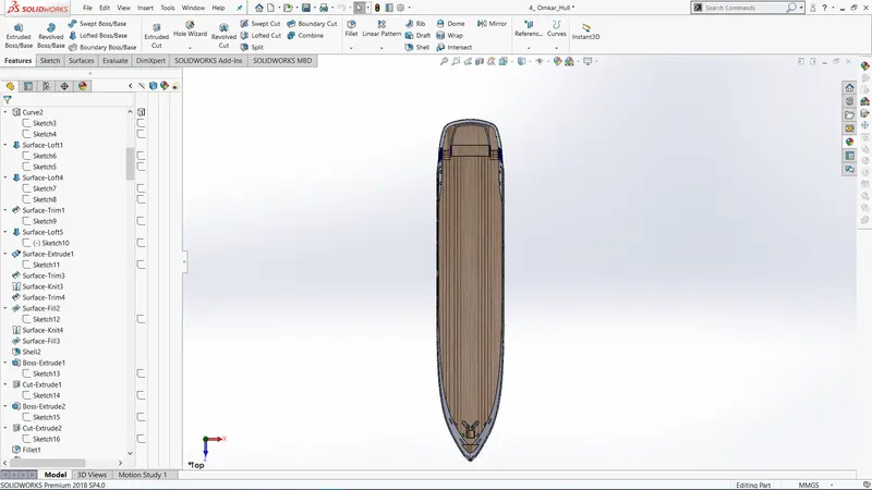
Figure16
Front view (with expanded feature tree):
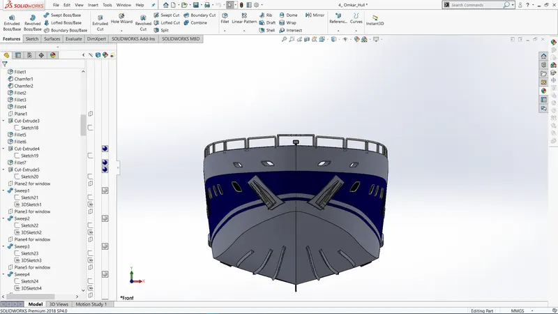
Figure17
Right hand side view (with expanded feature tree):
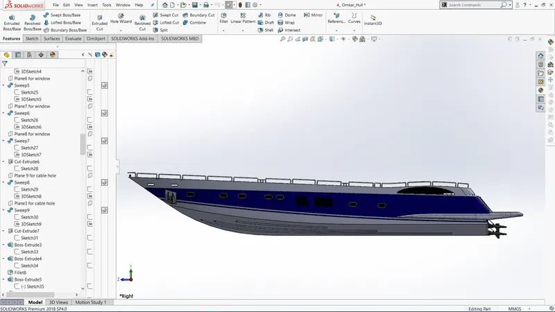
Figure18
Left hand side view (with expanded feature tree):
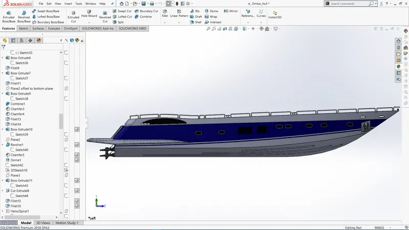
Figure19
Back view (with expanded feature tree):
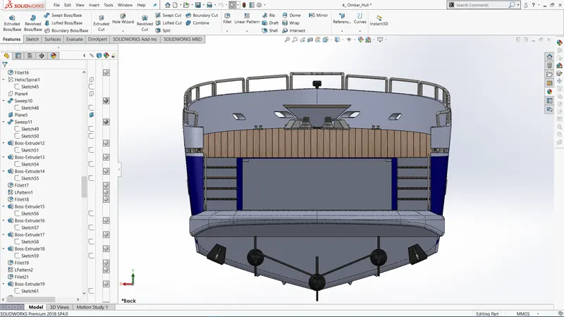
Figure20
Bottom view (with expanded feature tree):
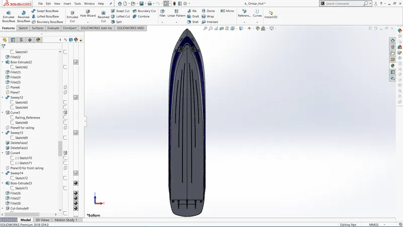
Figure21
Rest of the feature tree:
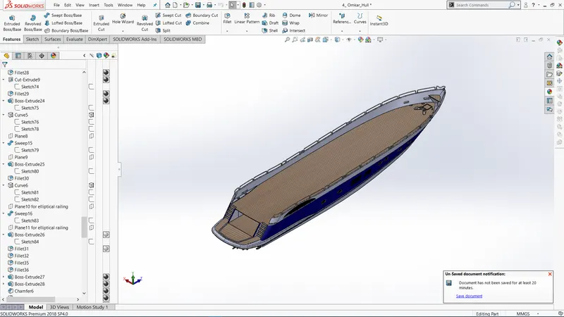
Figure22
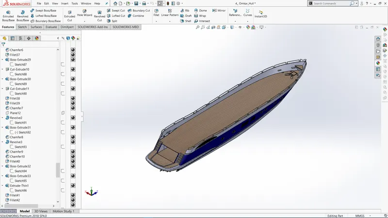
Figure23
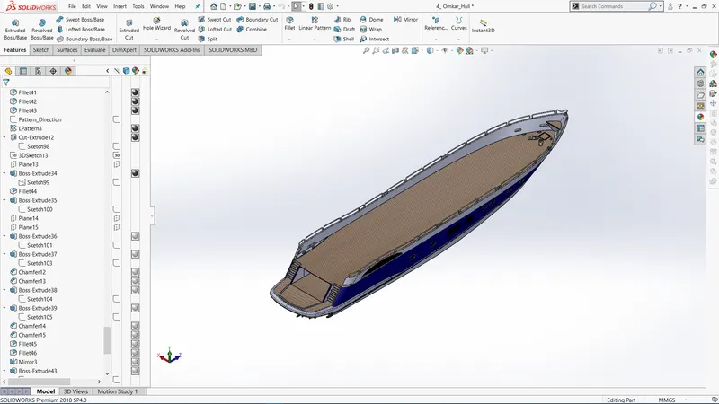
Figure24
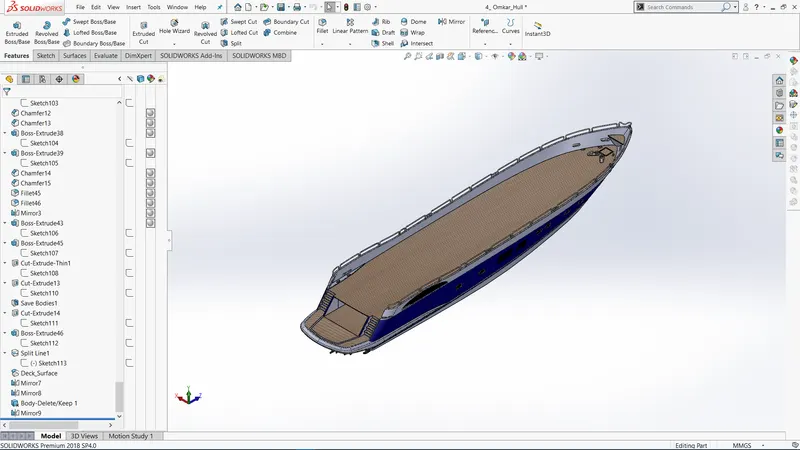
Figure25
- Garage Door
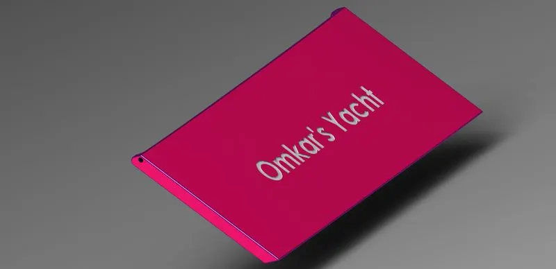
Sketch tools used:
- Lines
- Circle
- Text
Features Used:
- Extruded Cut
- Shell
- Fillet
- Mirror
- Reference Plane
- Appearance
Isometric view (with expanded feature tree):
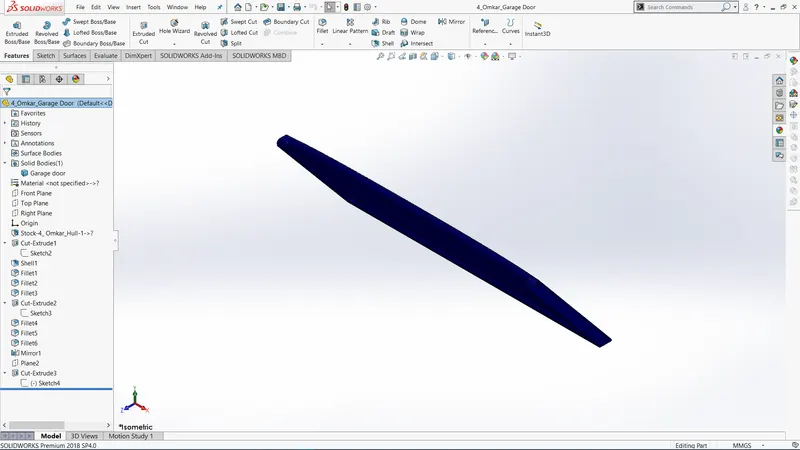
Figure26
Back view (with expanded feature tree):
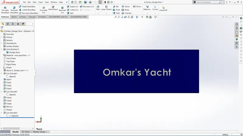
Figure27
Left hand side view (with expanded feature tree):
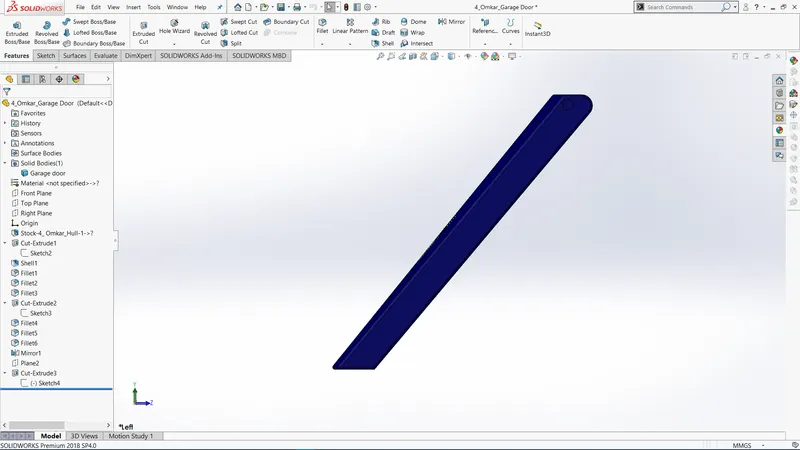
Figure28
Top view (with expanded feature tree):
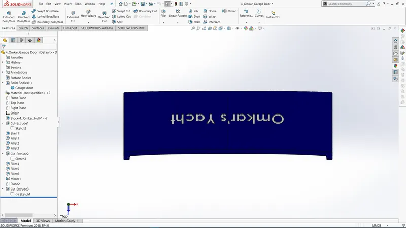
Figure29
- Front Seat
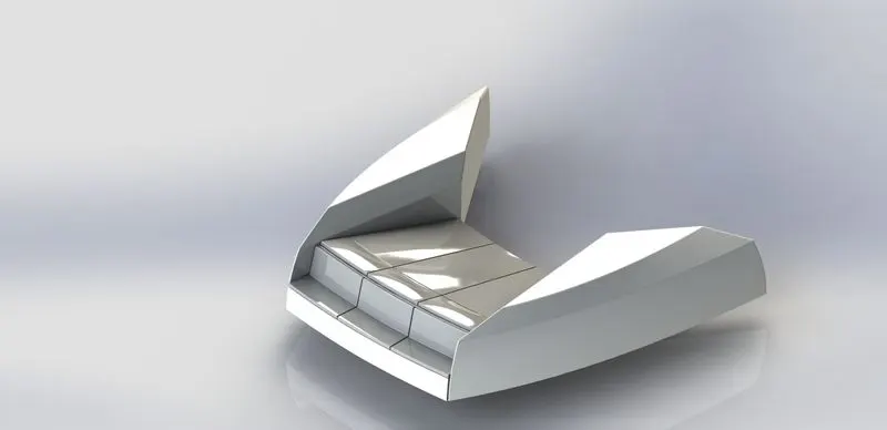
Sketch tools used:
- Lines
- Splines
- Construction Line
- Corner Rectangle
Features Used:
- Surface Sweep
- Surface Extrude
- Surface Trim
- Surface fill
- Surface Trim
- Surface Loft
- Surface Knit
- Chamfer
- Revolve boss/base
- Extruded cut
- Fillet
- Mirror
- Dome
- Appearance
Isometric View (with expanded feature tree):
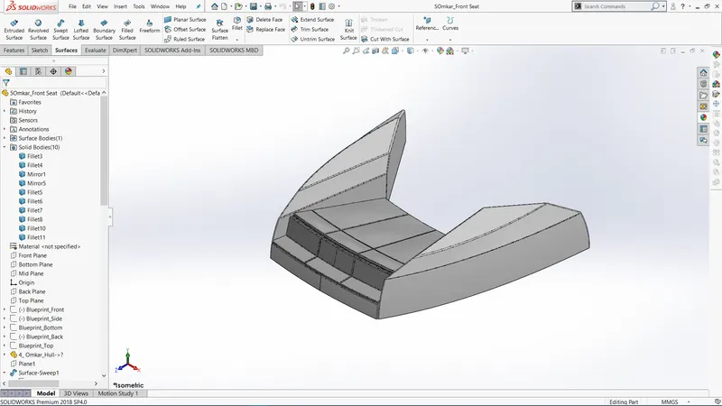
Figure30
Front View (with expanded feature tree):
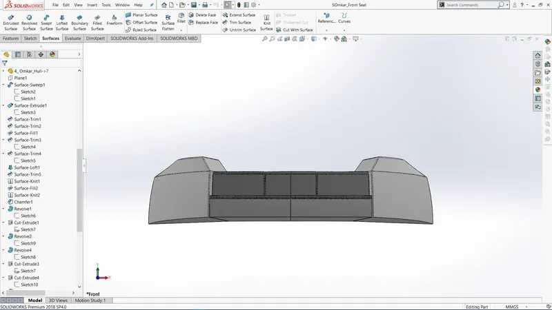
Figure31
Right Hand Side View (with expanded feature tree):
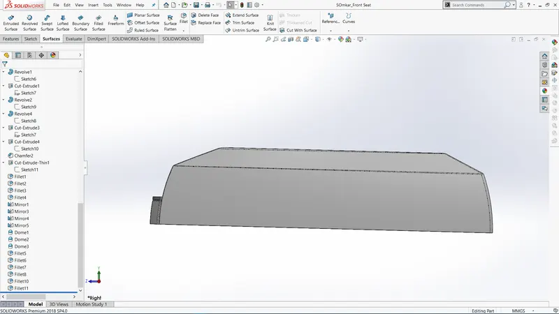
Figure31
Top View (with expanded feature tree):
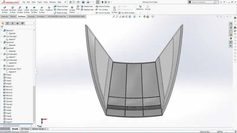
Figure32
- Middle Seat
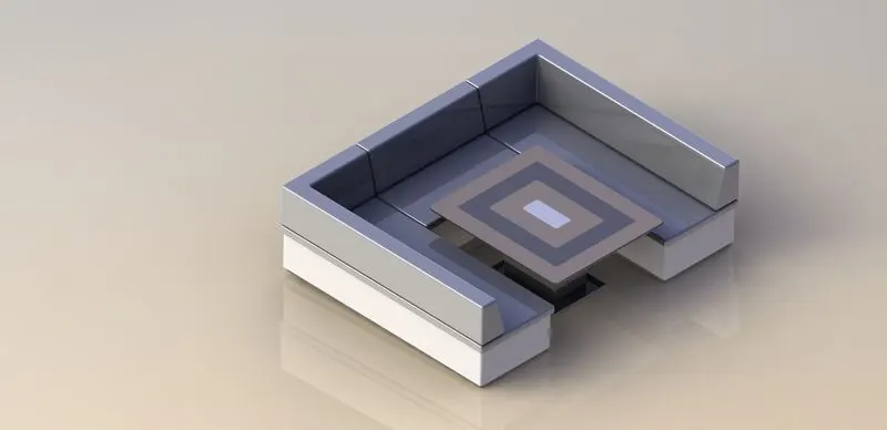
Sketch tools used:
- Lines
- Corner Rectangle
Features Used:
- Extrude Boss/Base
- Reference Plane
- Chamfer
- Fillet
- Mirror
- Extruded Cut
Isometric View (with expanded feature tree):
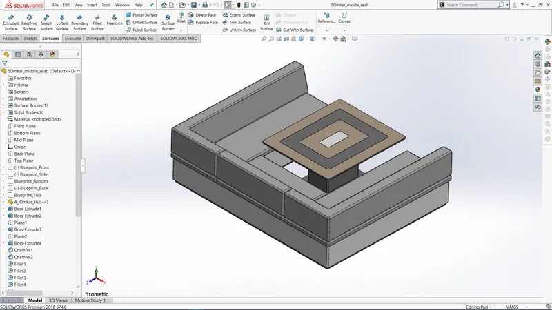
Figure33
Front View (with expanded feature tree):
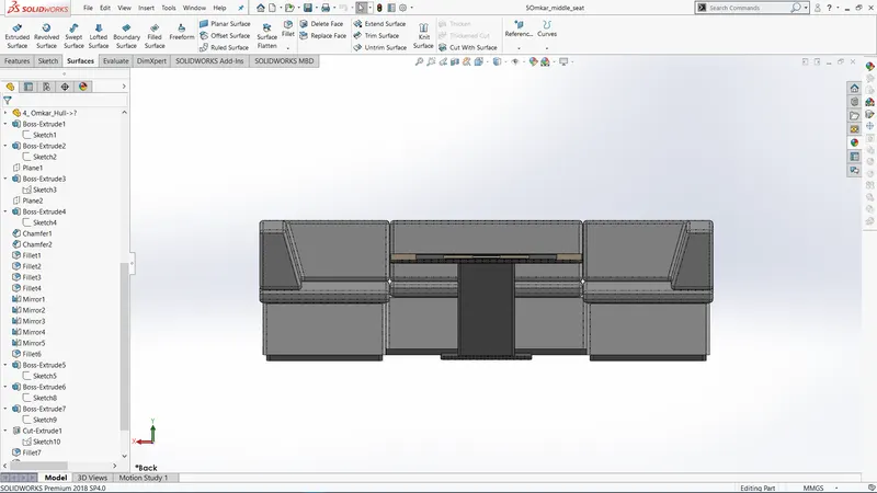
Figure34
Top View (with expanded feature tree):
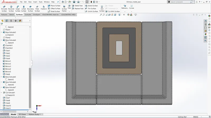
Figure35
- Rear Seat
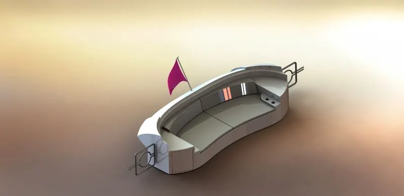
Sketch tools used:
- Lines
- Splines
- Construction Line
- Convert entity
- Circles
- 3D Sketch
- Sketch Offset
- Corner Rectangle
- Power Trim
Features Used:
- Surface Sweep
- Surface Offset
- Surface Trim
- Ruled Surface
- Surface Knit
- Surface Extend
- Surface Loft
- Surface Extrude
- Extrude Boss/Base
- Solid loft
- Reference Plane
- Chamfer
- Fillet
- Mirror
- Extruded Cut
- Revolve Boss/Base
Isometric View (with expanded feature tree):
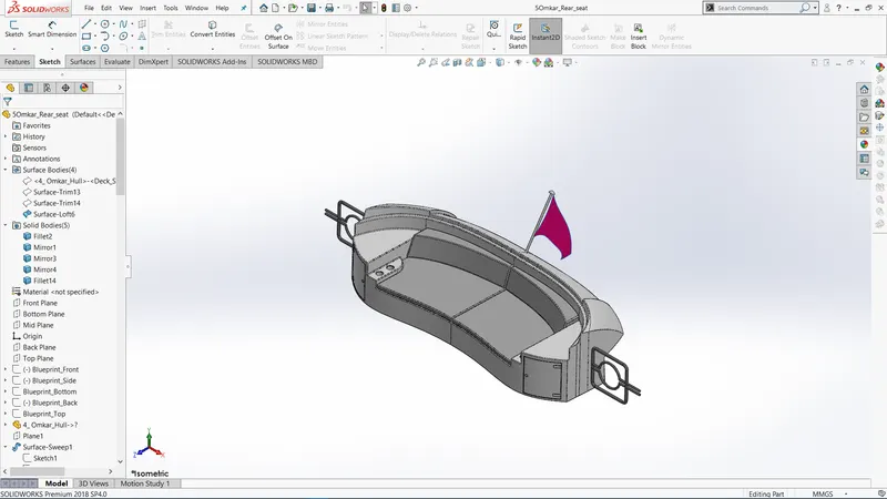
Figure36
Front View (with expanded feature tree):
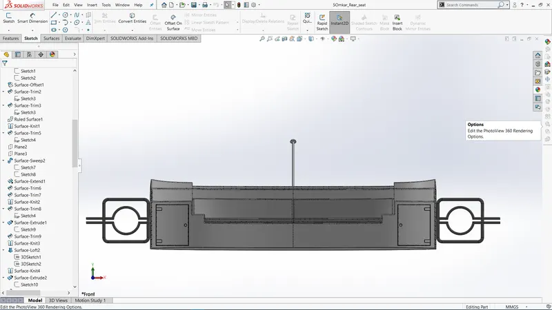
Figure37
Right hand Side View (with expanded feature tree):
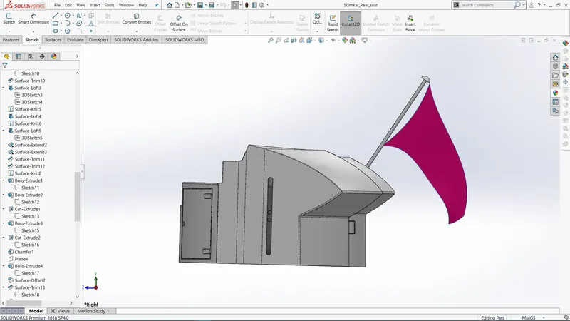
Figure38
Top View (with expanded feature tree):
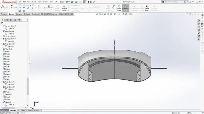
Figure39
Rest of the Expanded feature tree:
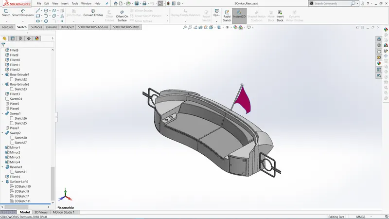
Figure40
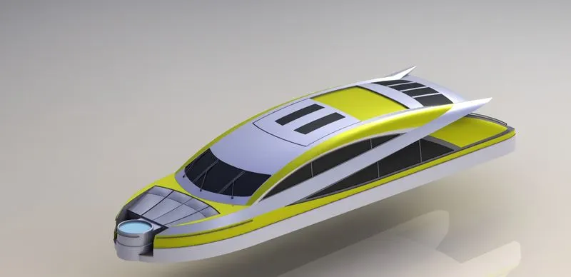
- Superstructure
Sketch tools used:
- Lines
- Splines
- Construction lines
- 3-point corner rectangle
- Corner rectangle
- Circle
- Centre point arc
- Sketch fillet
- 3D Sketch
- Convert entities
- Offset entities
- Power Trim
- Extend
Features Used:
- Extruded Surface
- Lofted Surface
- Swept Surface
- Filled Surface
- Ruled Surface
- Offset Surface
- Fillet
- Chamfer
- Delete Face
- Extend Surface
- Trim Surface
- Knit Surface
- Thicken
- Reference Planes
- Projected curves
- Split Line
- Extruded Boss/Base
- Swept Boss/Base
- Extruded Cut
- Dome
- Mirror
- Appearances
- Decals
Isometric View (with expanded feature tree):
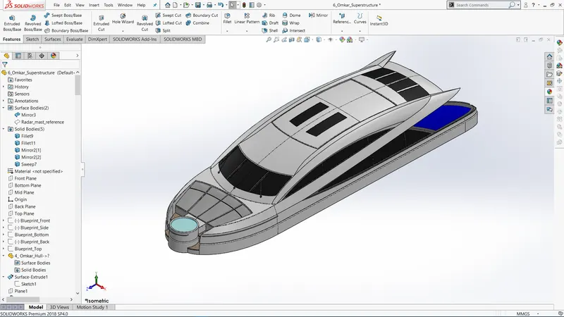
Figure41
Front view (with expanded feature tree):
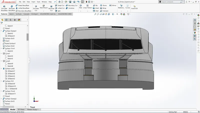
Figure42
Back view (with expanded feature tree):
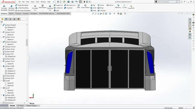
Figure43
Left hand side view (with expanded feature tree):
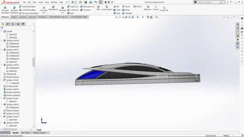
Figure44
Right hand side view (with expanded feature tree):
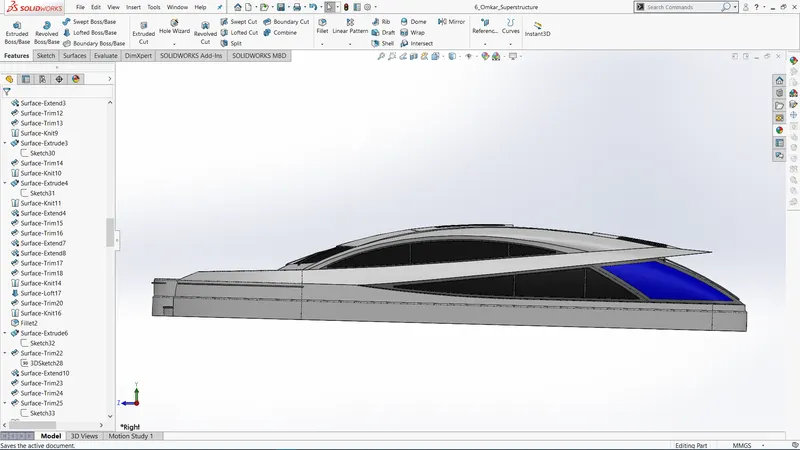
Figure45
Top view (with expanded feature tree):
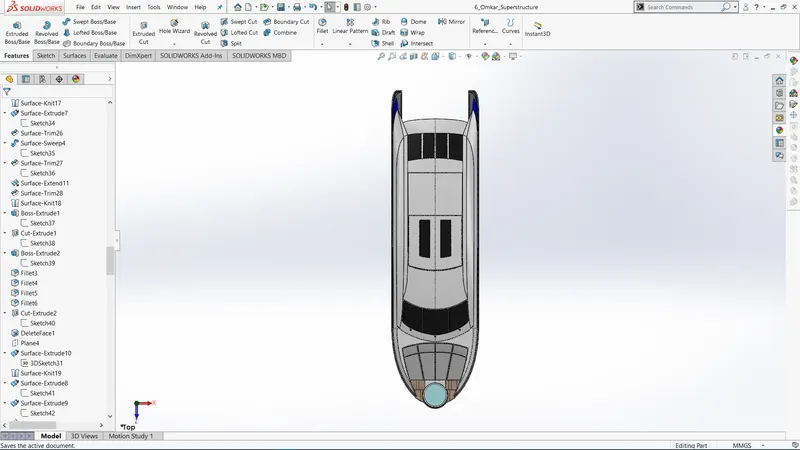
Figure46
Bottom view (with expanded feature tree):
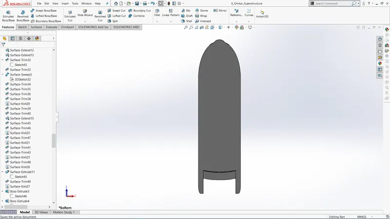
Figure47
Other view1 (with expanded feature tree):
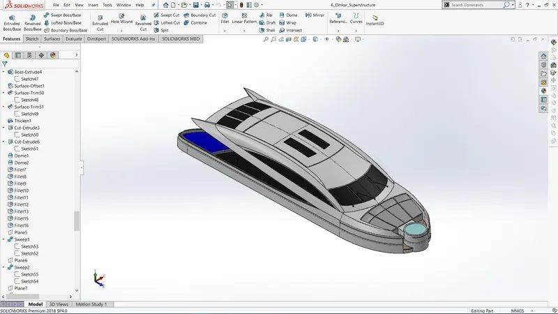
Figure48
Other view2(with expanded feature tree):
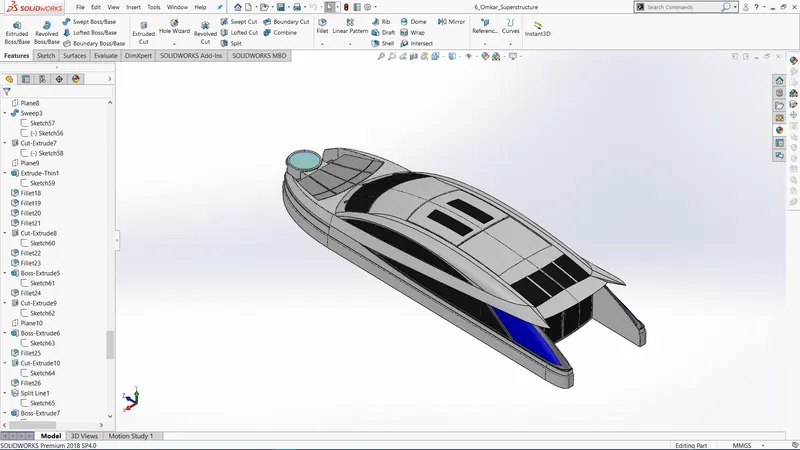
Figure49
Other view3(with expanded feature tree):
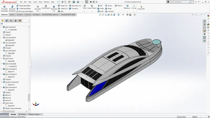
Figure50
Other view4(with expanded feature tree):
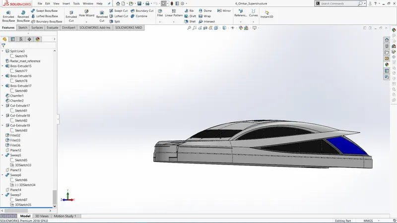
Figure51
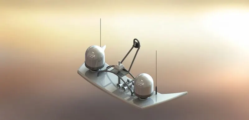
- Radar Mast
Sketch tools used:
- Lines
- Splines
- Construction lines
- Corner rectangle
- Circle
- 3D Sketch
- Convert entities
Features Used:
- Extruded Boss/Base
- Swept Boss/Base
- Fillet
- Chamfer
- Reference Planes
- Projected curves
- Extruded Cut
- Dome
- Revolve Boss /Base
- Shell
- Mirror
- Appearances
- Decals
Isometric View (with expanded feature tree):
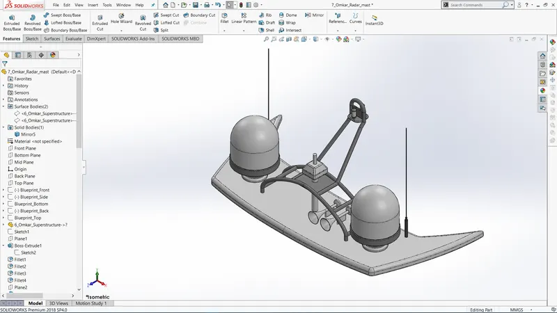
Figure52
Right hand Side View (with expanded feature tree):
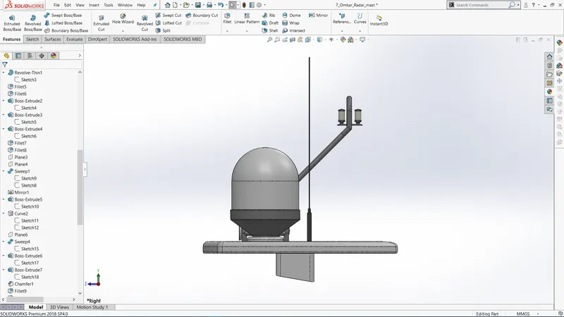
Figure53
Top View (with expanded feature tree):
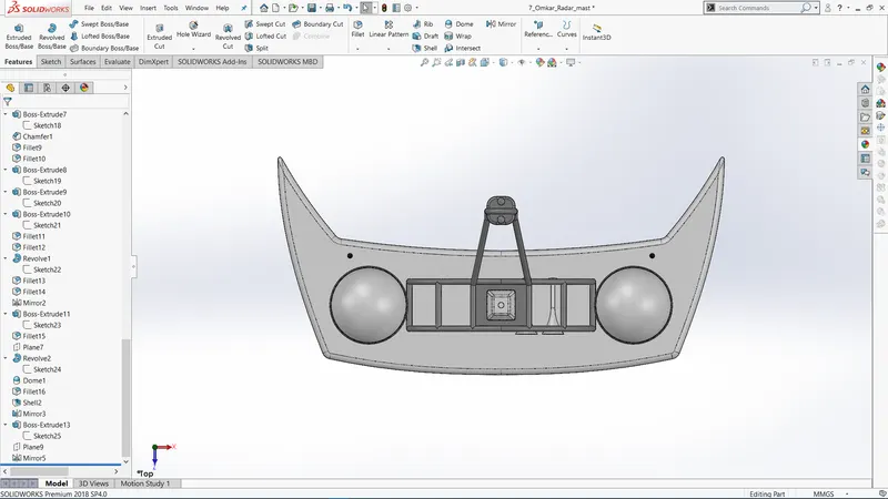
Figure54
- Assembly of Sunseeker Predator Yacht:
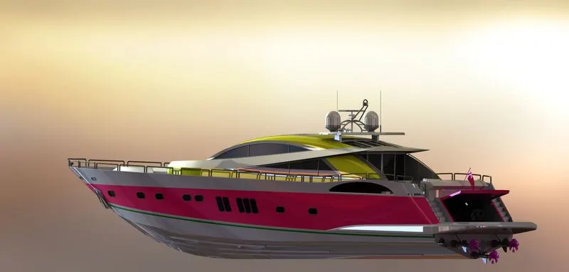
The assembly of the Predator Yacht consists of all the parts attached in appropriate manner with proper mates. The main component Hull is first fixed and other parts are mated with respect to its position.
Mates in assembly: Mates in assembly environment is analogous to relations in part environment. Basically, it is the relation between two different components. Solidworks assembly mates consists of 3 main mates namely Standard mates, Advanced mates and Mechanical mates.
Standard mates consist of: Coincident, Concentric, Parallel, Perpendicular, Tangent, Lock, Mate alignment angles and distance mates.
Advanced mates consist of Profile centre, Symmetric, Path mate, Width mate, Linear/Linear coupler, Angle and distance mates.
Mechanical mates consist of Cam, Slot, Hinge, Gear, Rack & Pinion, Screw, Universal joint.
The analysis tab under mates is used to define motion analysis between two components. The mates applied to the Yacht assembly are shown in figure below:
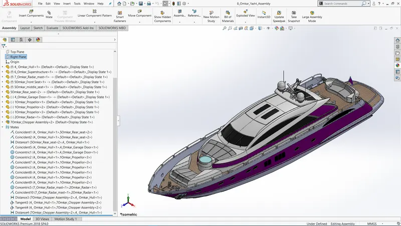
Figure54
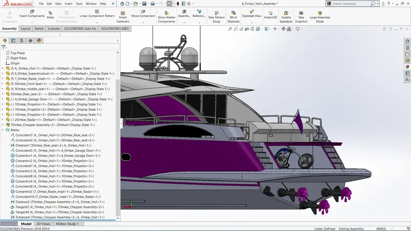
Figure55
Procedure for Assembly:
- Fix the Hull in assembly.
- Bring in Superstructure and fix it.
- Bring in radar mast and fix it.
- Insert all the other components
- Rear seat:
- Coincident relation between Mid Plane of Rear seat and Mid Plane of Hull.
- Coincident relation between base of rear seat and deck surface.
- End point of rear seat at a distance of 100mm from the end point of deck.
- Front seat:
- Coincident relation between Mid Plane of Front seat and Mid Plane of Hull.
- Coincident relation between Bottom face of Front seat and Deck surface of Hull.
- Middle seat:
- Coincident relation between Mid Plane of Middle seat and Mid Plane of Hull.
- Coincident relation between Bottom face of Middle seat and Deck surface of Hull.
- Garage Door:
- Concentric relation between the hinges of Garage door and the extruded hinge connection on Hull.
- Coincident relation between hinge and hull surface.
- Propellor:
- Concentric relation between propellor hole and Shaft on Hull.
- Coincident relation between propellor hole face and Shaft end face.
- Same for all Propellor
- Radar:
- Concentric relation between radar mast shaft and hole of radar
- Coincident relation between radar hole inner face and mast shaft outer face.
- Chopper motorcycle
- Import assembly of chopper motorcycle and try to fit it inside the Garage.
- Make Midplane of Chopper at a distance of 750mm from Midplane of Hull.
- Make the both tyres Tangent in relation to the Garage deck surface.
- Give a distance mate between a fixed component of motorcycle, in this case the engine mount face and the Garage borderline.
- Save The Assembly.
➢ Photorealistic Rendering
Rendering of the assembly is done to make a good quality 2D images for the purpose of advertising and promotion of the products before selling it to the customers. Photorealistic rendering creates high quality images or motion graphics if available so as to look appealing in various environments and backdrops. Solidworks provides 2 rendering products:
- Photoview 360 which is inbuilt add in for Solidworks
- Solidworks Visualize which is a separate Render Engine.
➢ Photoview 360:
- After adding photoview 360 the render tools tab can be brought in.
- It has various options like preview window, render region, final render, edit appearance, edit scenes, and options for managing render quality, Bloom, cartoon, direct caustics, network rendering and final image type.
- Schedule render and recall last renders are also some options.
- Decals can be added using edit decals, image can be added on faces by mapping values in coordinate directions. Illumination can be set to underlying appearance for better blending of decals.
- Display states can be set for parts individually so as to provide multiple appearances to a single part and changing the appearance whenever required.
- From view dropdown- Lights and camera is for setting up camera views and lighting of the scenes.
➢ Solidworks Visualize:
- Solidworks Visualize provides a suite of standalone software tools that combine industry-leading rendering capabilities with visual design-oriented features and workflows, allowing easy and fast creation of visual content that communicates a design’s vision, passion, and emotion.
- It is a separate render engine that is provided under Solidworks professional.
- Visualize Professional adds an array of features including animations, custom lighting, VR, 360 Interactive, and much more.
- Solidworks Visualize Professional provides the highest level of detail and optimized render times.
- It helps in creating Rendered images of the Solidworks models in Photorealistic environments for marketing quality images with various options to tweak on the final image required as per the user.
- It uses either of the CPU or GPU or both as hybrid to render quality images.
- Import the assembly and select part grouping as appearance, this ensures that all the parts having same appearance are grouped together in appearance tab.
- All parts having same appearance can be tweaked together using appearance options.
- Setting up of background can be done from scenes tab which includes a wide range of HDR images and backgrounds.
- Background brightness, rotation, gamma can be changes as required from the scenes tab.
- Camera views can be added or used from assembly.
- Render output image properties can be changed from output tools. Things such as image size, animation, photograph scenes, usage of CPU, GPU or both as hybrid can be selected
Rendered Images:
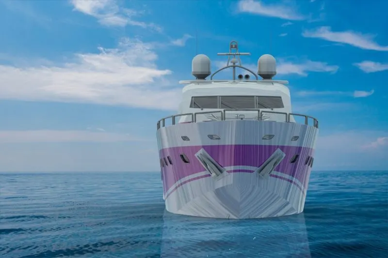
Figure56
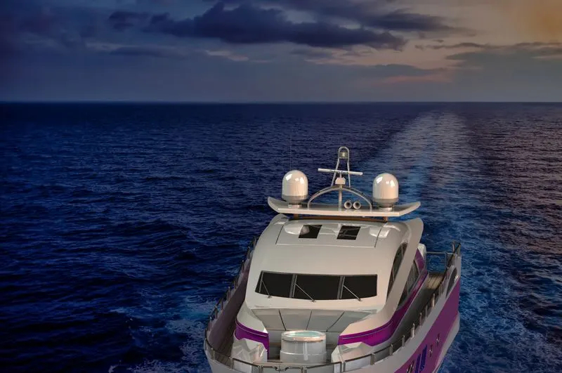
Figure57
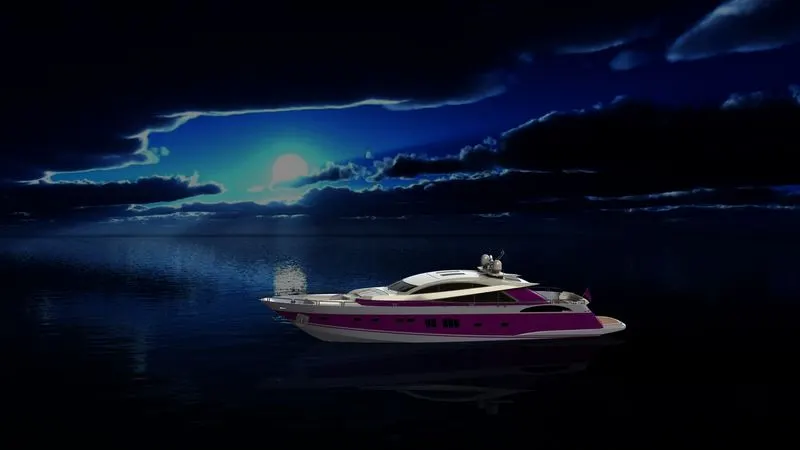
Figure58
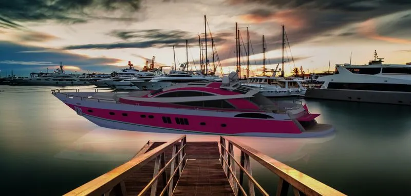
Figure59
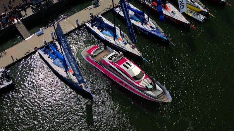
Figure60
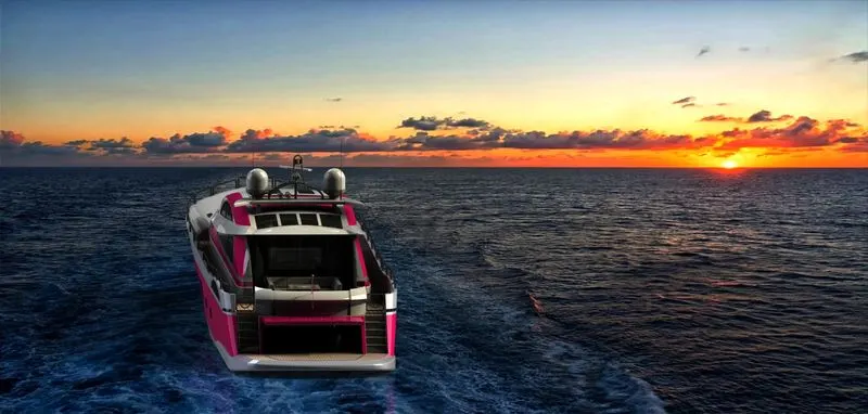
Figure61

Figure62
Views of the Final Assembly:
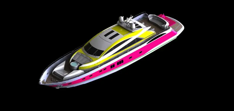
Isometric View:
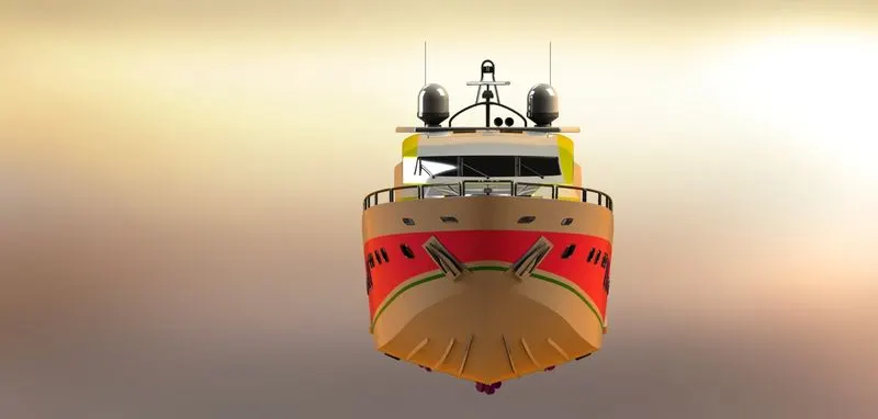
Front View:
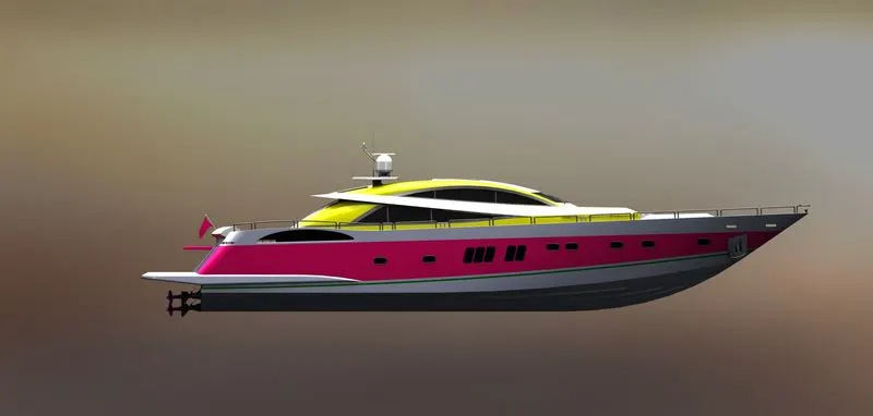
Side View:
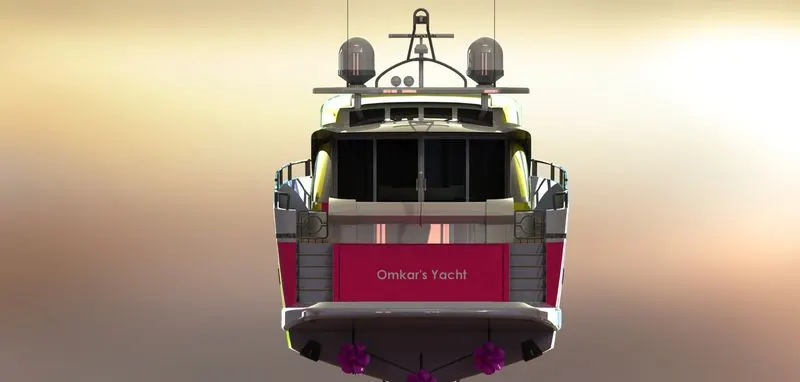
Back view:
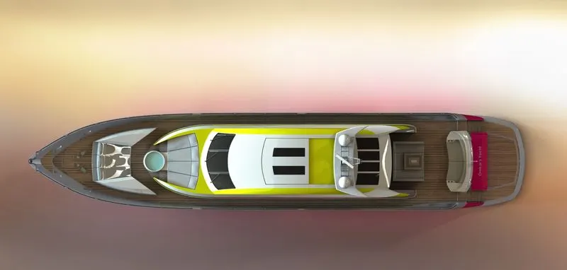
Top view:
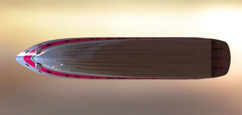
Bottom View:
Conclusion: Design, Assembly and Photorealistic rendering of Sunseeker Predator Yacht using Solidworks was successfully completed and the method of Solid modelling, Surface modelling, Assembly and rendering was understood and practiced.