Week 9 - Project 1 - Door Applique Design with Engineering Features
AIM:
To create a tooling axis, extract B-surface and C surface from the given Class-A surface and create 4-way and 2-way locator with heat stakes. To perform draft analysis on a solid body, locators and the heat stakes created by the Class-A surface.
PROCEDURE:
Firstly, open the model using the open command.
TOOLING AXIS:
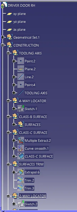
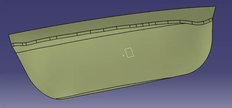
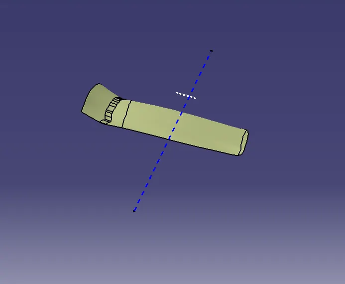
Create a point, plane and Create a line on the Z direction by projecting the class-A surface on the sketch and rename it as Tooling axis.
CLASS-B SURFACE:
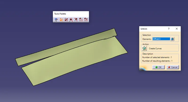
To create B surface, extract the class-A surfaces, untrim and extrapolate it.
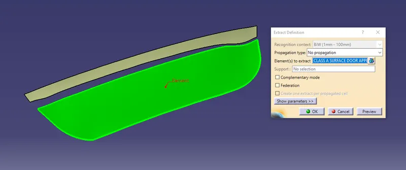
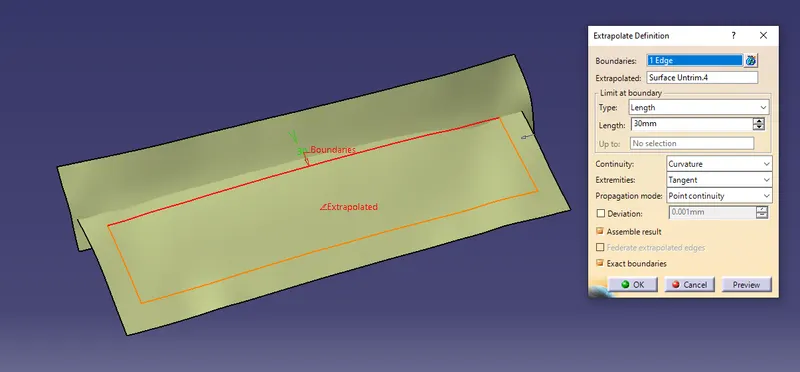
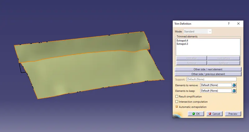
After extrapolating, trim the wall attached surfaces.
Now, offset the surfaces at a value of 2.5mm below.
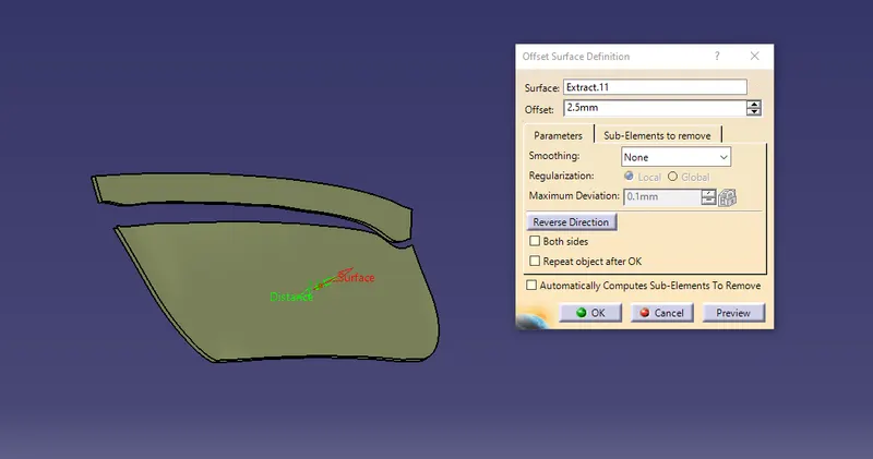
After offsetting the surface trim the B-surface.
Then give the edge fillet to it.

Now the Class-B surface is created.
CLASS-C SURFACE:
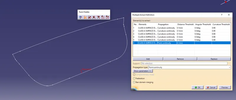
To create a Class-C surface, use the multi extract command and extract the boundaries.
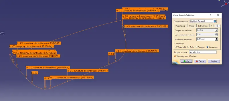
Smooth the extracted curve using a smooth curve command.
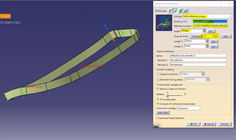
Then use the sweep command to create a surface using reference with surface option.
ATTACHING A-C-B:
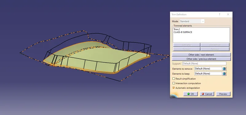
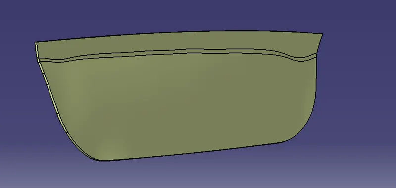
After all the surfaces are created Trim the Class-A and Class-C surfaces
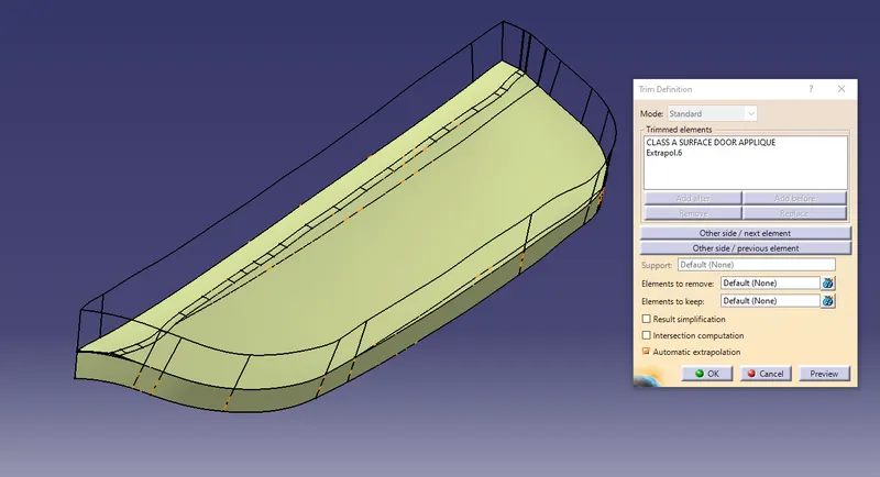
Now, trim it with Class-B surface.
CREATING SOLID BODY:
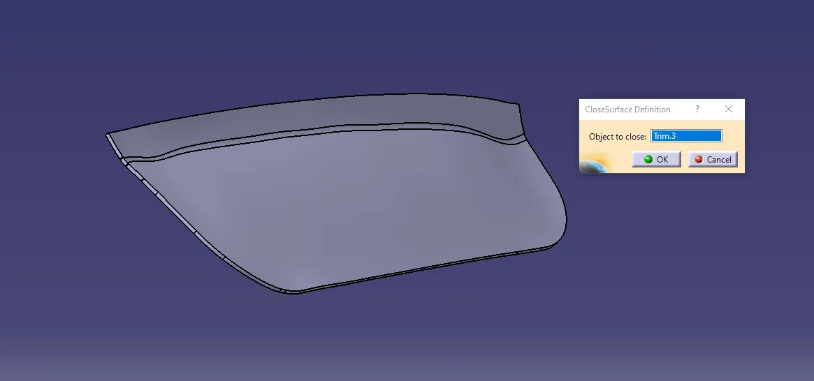
Now, create a part body and select a closed solid.
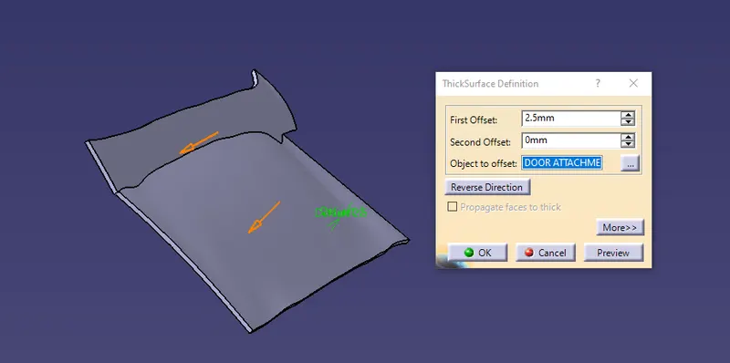
Now thicken the reference surface to 2.5mm.
LOCATORS:
To create a 2 and 4-way locator create a sketch and Iso-constraint it.
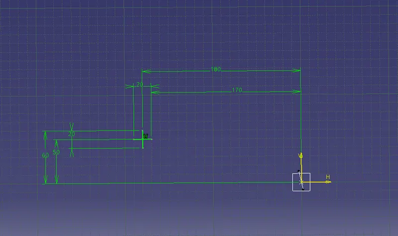
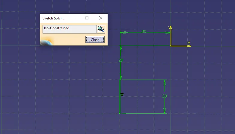
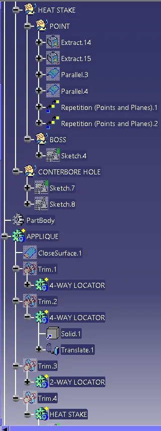
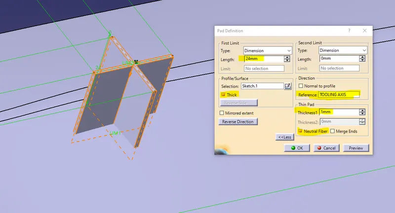
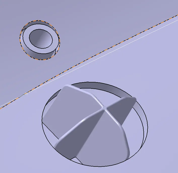
Goto part design creates a part body and pad with neutral fibre 1mm thickness.
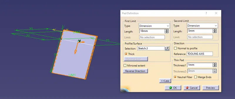
Now chamfer, draft and give edge fillets to the locator.
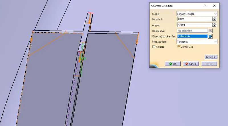
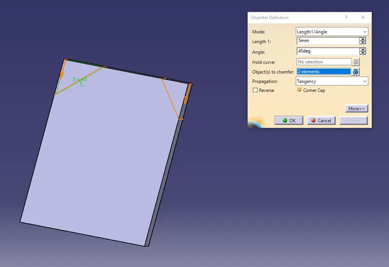
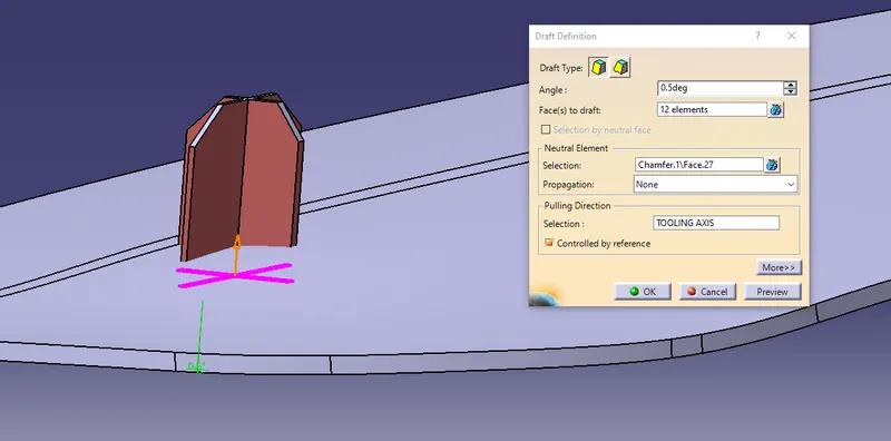
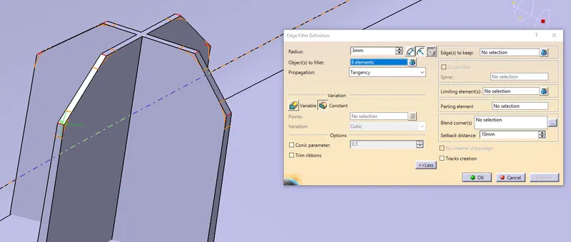
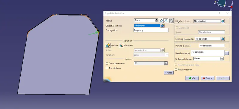
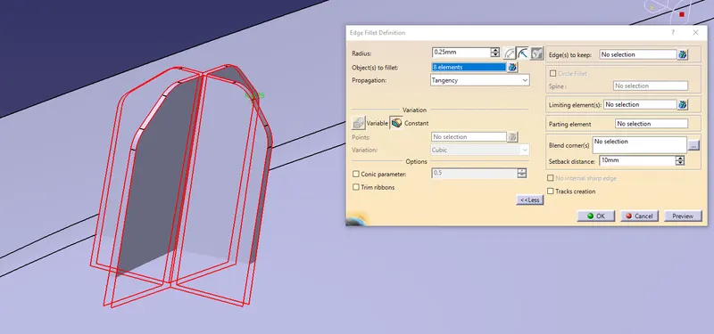
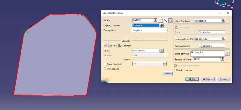
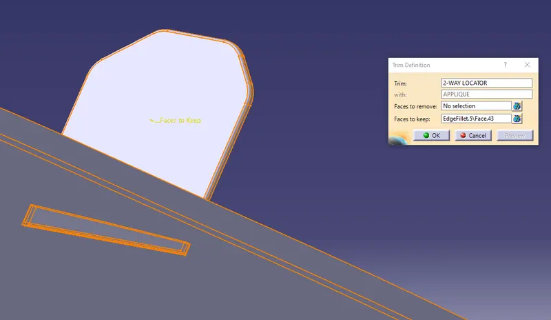
Now union trim it with the closed solid.
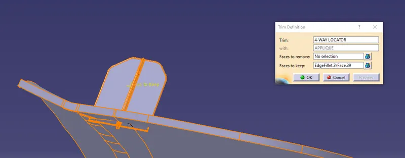
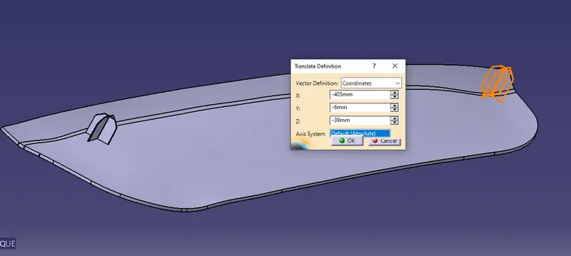
Similarly, copy the locator and paste special with a link then translate it.
HEAT STAKES:
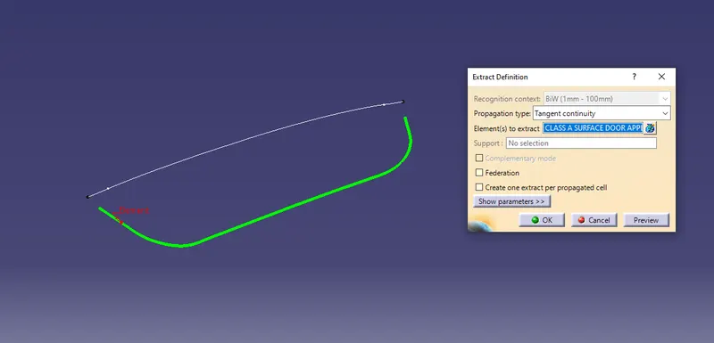
To create heat stakes, first, extract the Class-A surface boundary with tangency continuity.
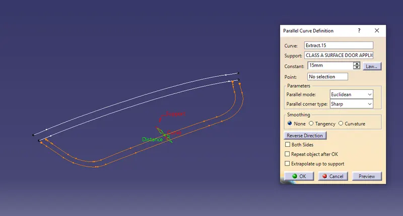
Offset the extracted boundary using a parallel curve command to 15mm.
Create points using point repetition command by selecting the curve and giving instances.
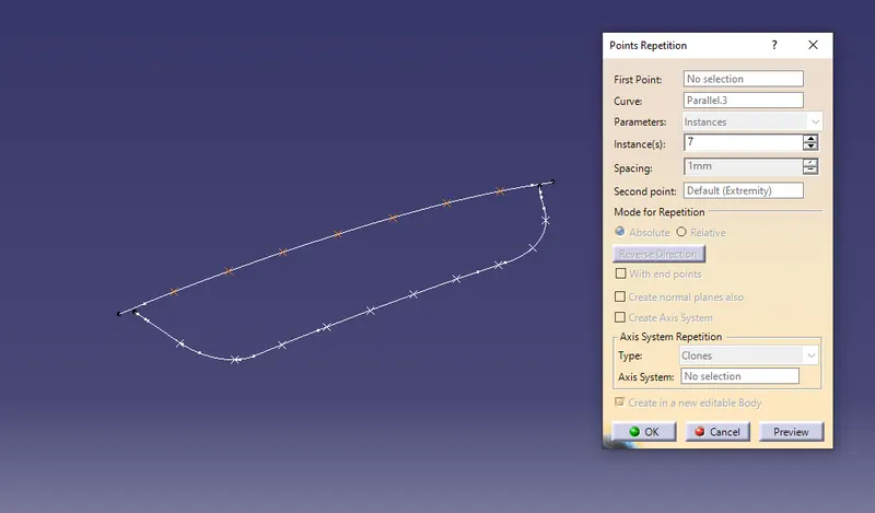
Now create a sketch at that point and Iso-constraint it.
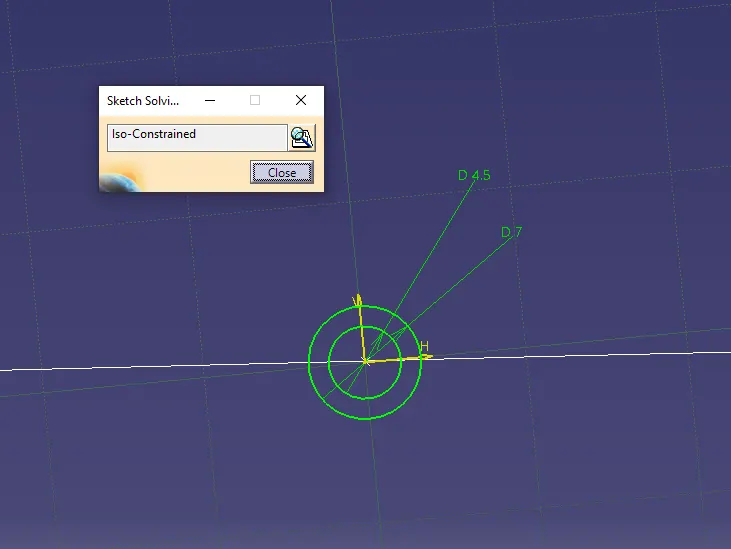
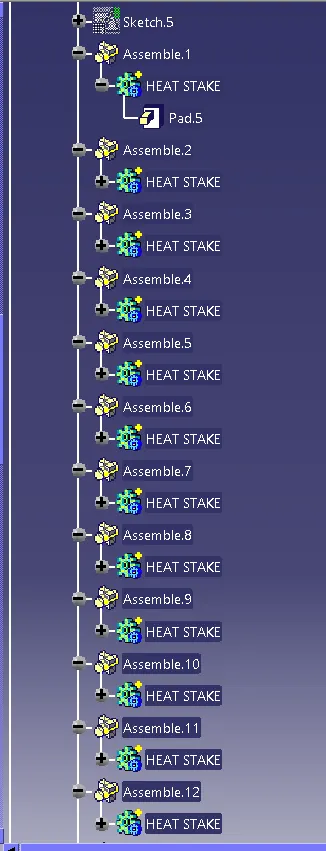
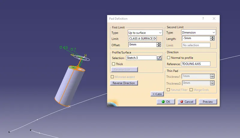
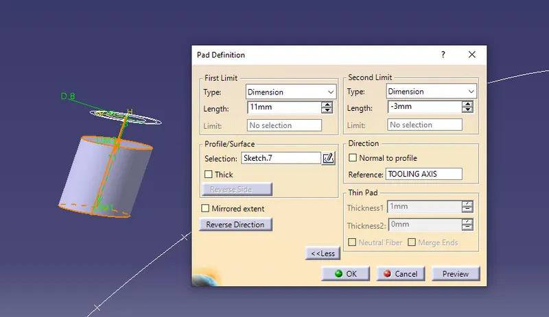
Create a part body, pad the sketch.
Now copy the sketch and paste special with link to the main part.
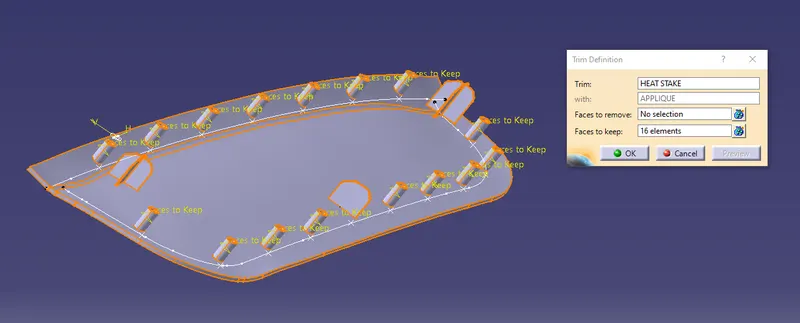
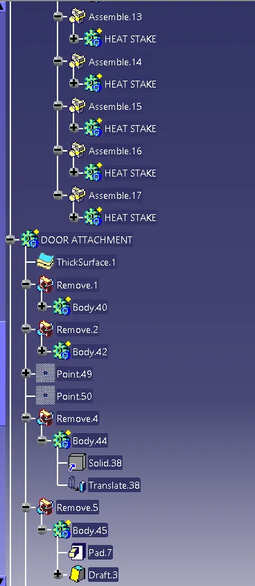
Remove it from the reference surface with a minimum clear less than 0.1mm.
DRAFT ANALYSIS:
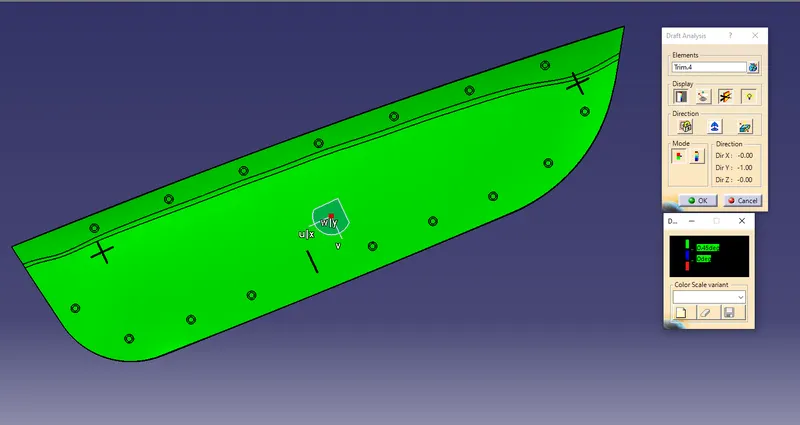
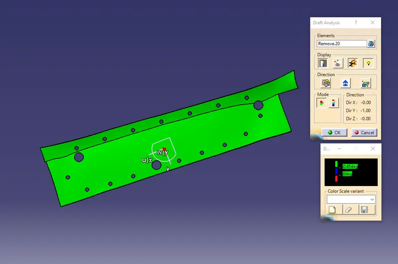
Draft Analysis is done on the solid body.
After the Tooling axis is created, the Draft analysis is done on the surface.
Select the Elements as the Class A Model and the Direction as the Tooling Axis using the Compass option to define a new
the direction of the draft.
Click OK to check if all the surface comes under the within the limits of 0 to 3 degrees.
If the draft is more than 3 Degree then the surface will be shown as green.
RESULT:
The Class B & C surfaces have been created using tooling axis, 2&4-way locator, heat stakes and drafting analysis are done on the solid body created by A, B and C surfaces.
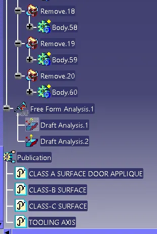
TREE STRUCTURE: