Week 9 - Parametric study on Gate valve.
AIMS AND OBJECTIVES
- To perform a parametric study on a gate valve simulation by setting the opening from 10% to 80%.
- To compute mass flow rate, flow coefficient, and flow factor at the outlet for each case.
- Compare and discuss the results of mass flow rate and flow coefficient.
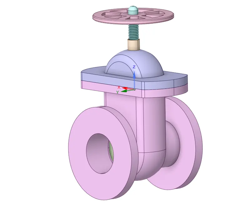
Gate Valve Model:
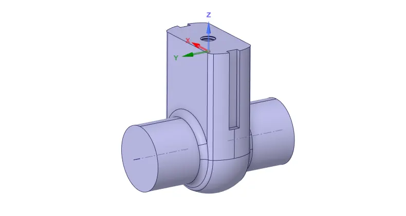
Fluid Volume Extracted:
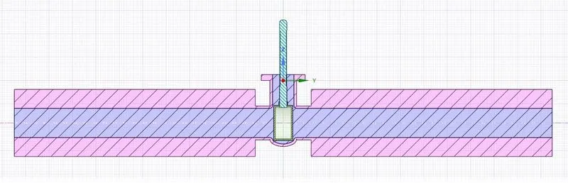
Initial Position of Gate Valve before any lift inputs:
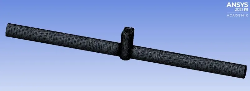
Meshing:
Element size chosen = 6 mm
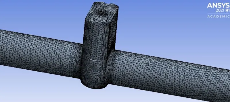
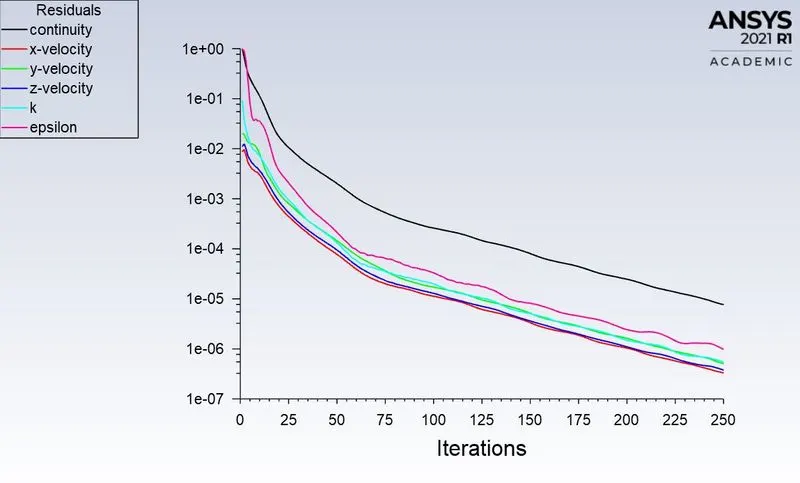
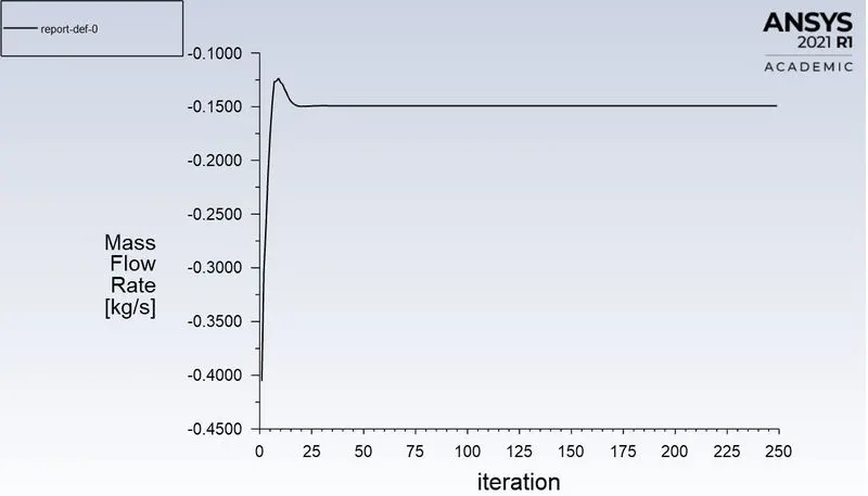
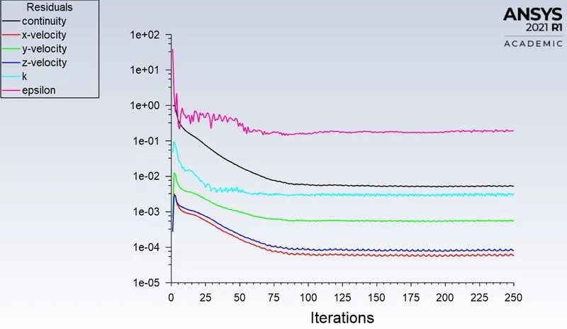
Here, pressure inlet boundary condition is applied at the inlet boundary with a gauge pressure value of 10 Pascal. The flow Reynolds number is found to be turbulent from the initial flow velocity and the viscous model chosen is k-epsilon Realizable with a scalable wall function. The cell zone is selected as water. Report definition is created for mass flow rate. The simulation is initiated with a standard initialization computed from the inlet and the whole simulation is run for about 250 iterations. The parameter is created beforehand for a specific gate lift displacement dimension in SpaceClaim as we are doing the parametric study. In the workbench, each design point of interest is enabled by clicking on 'set as current' after updating all the design points in the parameter option and associated mass flow rate values with respect to each design point is computed.
RESULTS
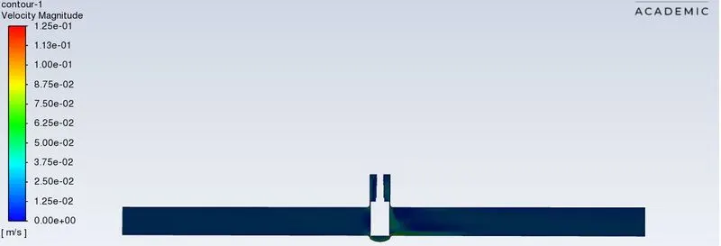
- Case 1: Gate Disc Lift = 10 mm
Convergence Plot:
Mass Flow Rate:
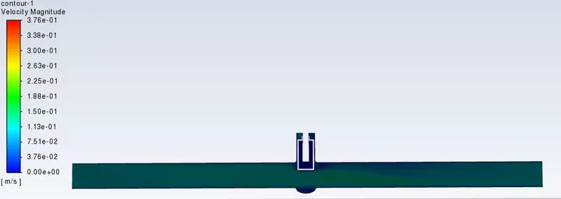
Velocity Contour:
- Case 2: Gate Disc Lift = 20 mm
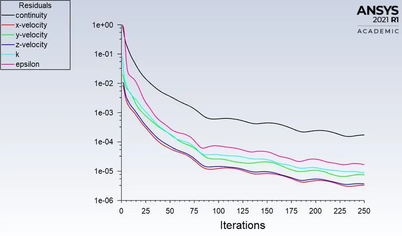
Convergence Plot:
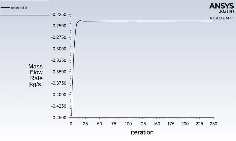
Mass Flow Rate:
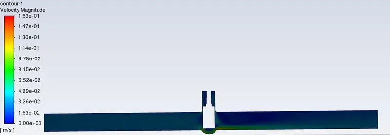
Velocity Contour:
- Case 3: Gate Disc Lift = 30 mm
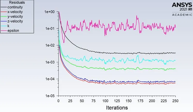
Convergence Plot:
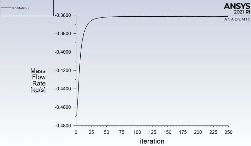
Mass Flow Rate:
Velocity Contour:
- Case 4: Gate Disc Lift = 40 mm
Convergence Plot:
Mass Flow Rate:
Velocity Contour:
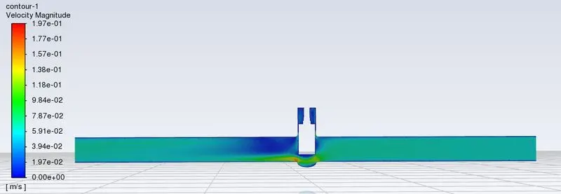
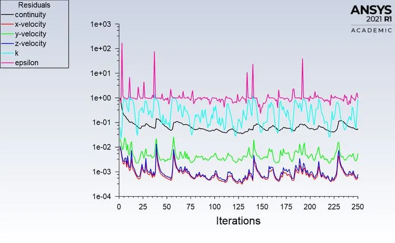
- Case 5: Gate Disc Lift = 50 mm
Convergence Plot:
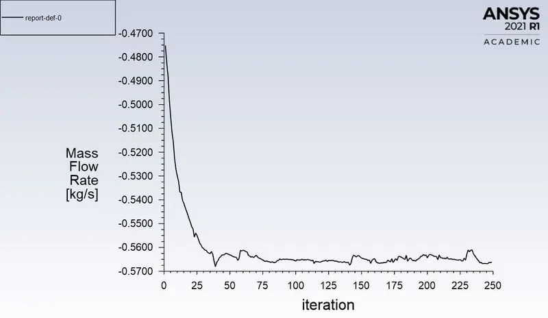
Mass Flow Rate:
Velocity Contour:
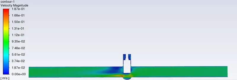
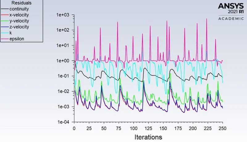
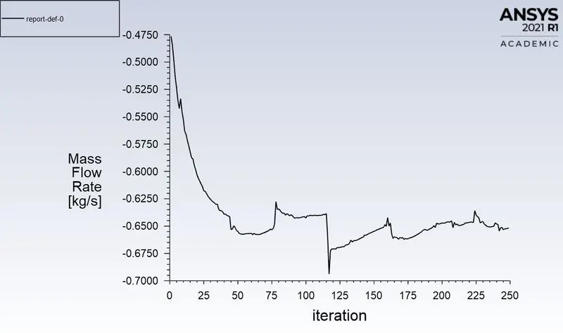
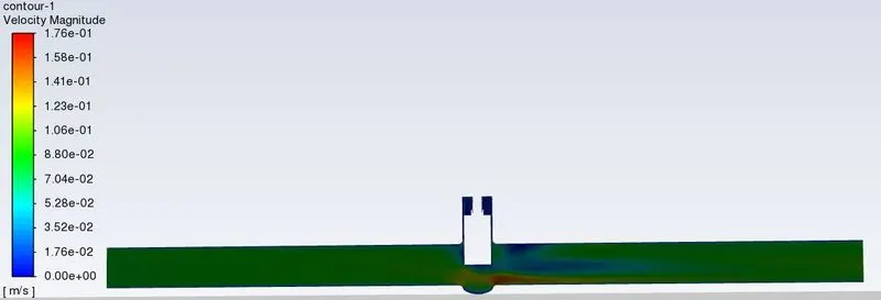
- Case 6: Gate Disc Lift = 60 mm
Convergence Plot:
Mass Flow Rate:
Velocity Contour:
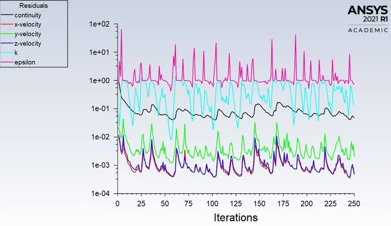
- Case 7: Gate Disc Lift = 70 mm
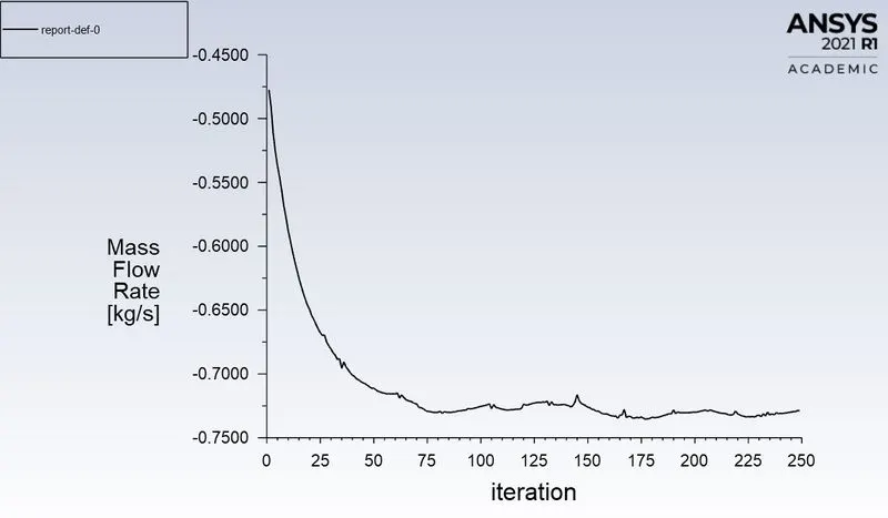
Convergence Plot:
Mass Flow Rate:
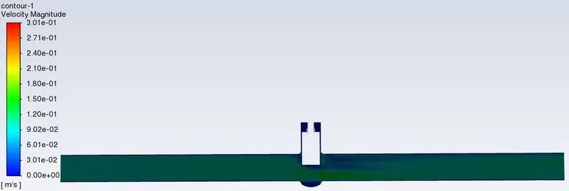
Velocity Contour:
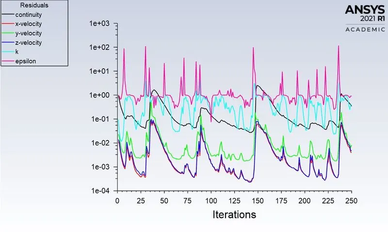
- Case 8: Gate Disc Lift = 80 mm
Convergence Plot:
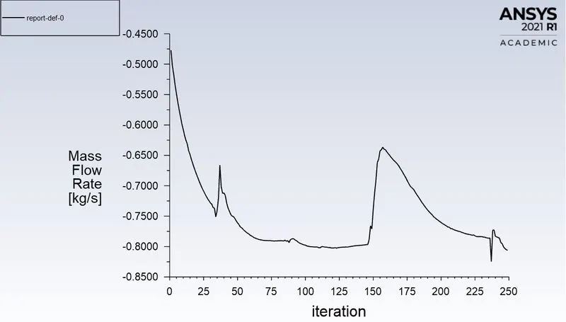
Mass Flow Rate:
Velocity Contour:
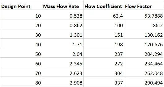
Calculation of Flow Coefficients and Flow Factors for each Design Points:
If SG is the specific gravity (here, for water, SG = 1), q is the mass flow rate (m³/hr) and dP is the pressure drop in kPa, then Flow Coefficient, Cv can be calculated by:
`Cv = q*sqrt((SG)/(dP))`
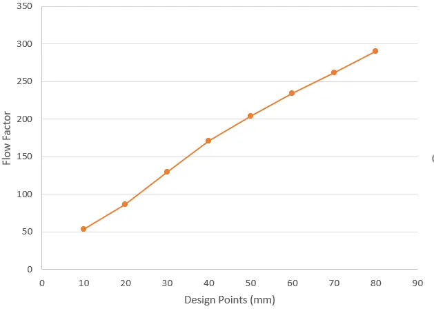
Also, Flow Factor, Kv = 0.862 * Cv
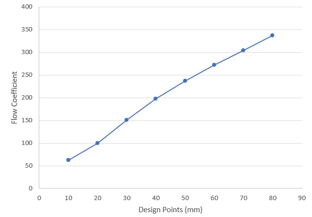
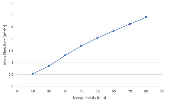
Applying the above two relationships of flow coefficient and flow factor with the mass flow rate, the values for each design point case can be computed and plotted as below:
Graphs:
Inference:
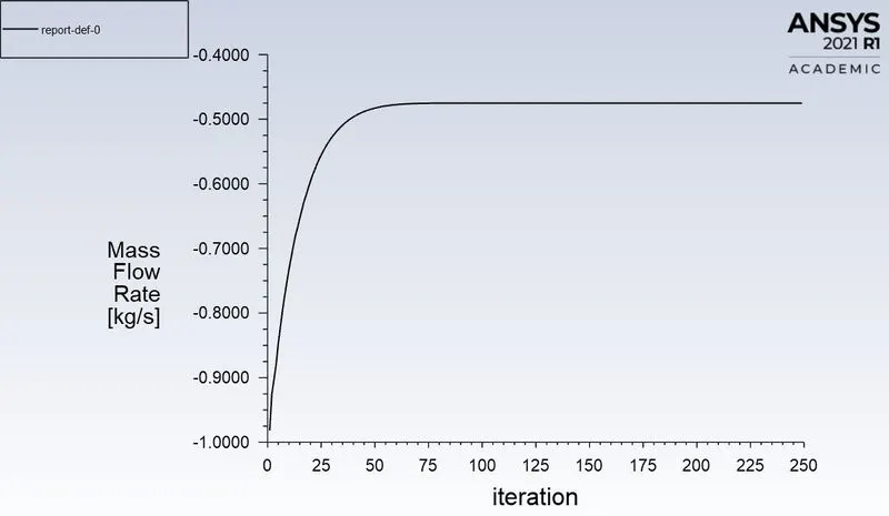
- The mass flow rate is observed to be increasing with the increment in gate valve lift.
- Similarly, since the flow coefficient is proportional to the mass flow rate as it can be seen from the formulae, the values of the flow coefficient increase with respect to the increase in gate valve lift.
- Hence, the efficiency of the gate valve at allowing the fluid through it keeping the same pressure drop throughout is maximum when the gate lift is more.
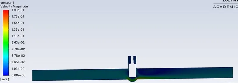
- The velocity contour also shows that the flow velocity is more when the opening displacement is more.