Week 8 - Simulation of a backward facing step in OpenFOAM
Objective: Here the objective is to simulate an incompressible laminar viscous flow through a backward-facing step geometry in OpenFOAM. Also, the simulation is performed for two case studies, one with a grading factor and one without it, and the respective results are compared. The results are post-processed in Paraview.
Given:
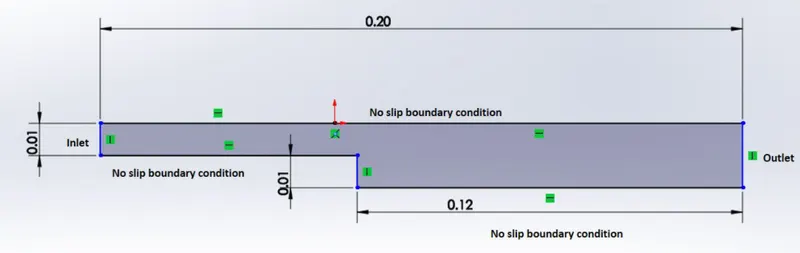
The backward-facing step geometry of the overall length of 0.2m is given as in the figure above. The lid-driven cavity tutorial available in the OpenFOAM platform can be used to modify to perform this simulation. The flow is assumed to be two-dimensional and hence the flow along the xy-plane is only taken into consideration. Based on the physics of flow, we choose icoFoam, which is essentially a transient solver for the incompressible flow to perform the time marching simulation.
The mesh parameters suggested to use:
The number of cells along longer x direction = 200
The number of cells along y direction =20
The grading factor (for finer mesh near the walls) = 0.2
Simulation Procedure:
- A terminal in the linux operating system is opened.
- The tutorial files in the openFOAM platform is accessed ('tut'-shortcut to access the tutorial directory from the home directory).
- The files are listed using the 'ls' command and 'cd incompressible/icoFoam' takes us to the icoFoam file in the incompressible folder. The files are listed and the cavity folder is copied (cp -r cavity $FOAM_RUN) to the $FOAM_RUN which is the run directory in the user folder that OpenFOAM creates.
- The shortcut command to access the $FOAM_RUN folder is 'run'. The copied cavity can now be able to access to manipulate.
- Now the cavity file is accessed by 'cd' command and the the files are listed using 'ls' command. The blockMeshDict file inside the system folder of cavity directory can be viewed using 'gedit' or 'vim' commands. The geometry of the problem is defined in this file.
blockMeshDict file :
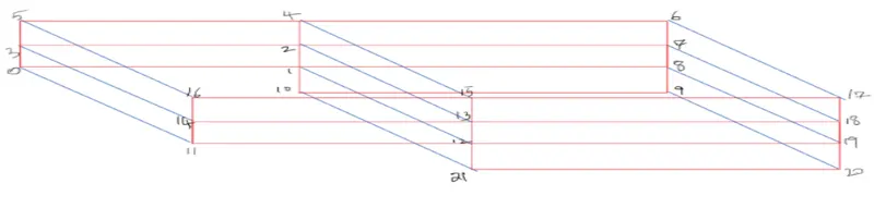
The given geometry is divided into five blocks as in the figure below. All the vertices are marked with the index starting from zero (since OpenFOAM uses c++ programming) to 21 according to our convenience. The vertices are defined in the blockMeshDict file by applying suitable scaling factors to convert it into SI units.
/*--------------------------------*- C++ -*----------------------------------*\
  =========                 |
  \\      /  F ield         | OpenFOAM: The Open Source CFD Toolbox
   \\    /   O peration     | Website:  https://openfoam.org
    \\  /    A nd           | Version:  7
     \\/     M anipulation  |
\*---------------------------------------------------------------------------*/
FoamFile
{
    version     2.0;
    format      ascii;
    class       dictionary;
    object      blockMeshDict;
}
// * * * * * * * * * * * * * * * * * * * * * * * * * * * * * * * * * * * * * //

convertToMeters 0.01;

vertices
(
    (0 0 0)   // vertex 0
    (8 0 0)   // vertex 1
    (8 0.5 0) // vertex 2
    (0 0.5 0) // vertex 3
    (8 1 0) // vertex 4
    (0 1 0) // vertex 5
    (20 1 0) // vertex 6
    (20 0.5 0) // vertex 7
    (20 0 0) // vertex 8
    (20 -1 0) // vertex 9
    (8 -1 0) // vertex 10
    (0 0 0.1)   // vertex 11
    (8 0 0.1)   // vertex 12
    (8 0.5 0.1) // vertex 13
    (0 0.5 0.1) // vertex 14
    (8 1 0.1) // vertex 15
    (0 1 0.1) // vertex 16
    (20 1 0.1) // vertex 17
    (20 0.5 0.1) // vertex 18
    (20 0 0.1)  // vertex 19
    (20 -1 0.1) // vertex 20
    (8 -1 0.1) // vertex 21
);

blocks
(
    hex (0 1 2 3 11 12 13 14) (100 20 1) simpleGrading (0.2 5 1) //block 0
    hex (3 2 4 5 14 13 15 16) (100 20 1) simpleGrading (0.2 0.2 1) //block 1
    hex (1 8 7 2 12 19 18 13) (100 20 1) simpleGrading (5 5 1) //block 2
    hex (2 7 6 4 13 18 17 15) (100 20 1) simpleGrading (5 0.2 1) //block 3
    hex (10 9 8 1 21 20 19 12) (100 20 1) simpleGrading (5 5 1) //block 4
);

edges
(
);

boundary
(
    inlet
    {
        type patch;
        faces
        (
            (0 11 14 3)
            (3 14 16 5)
        );
    }
    outlet
    {
        type patch;
        faces
        (
            (8 7 18 19)
            (9 8 19 20)
            (7 6 17 18)
        );
    }
    walls
    {
        type wall;
        faces
        (
            (4 5 16 15)
            (6 4 15 17)
            (1 10 21 12)
            (0 1 12 11)
            (10 9 20 21)
        );
    }

);

mergePatchPairs
(
);

// ************************************************************************* //
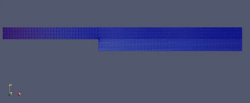
- Five blocks are defined with appropriate mesh specifications along xyz directions. Although 2-D flow is considered, three dimesnional spaces are taken into account for defining the mesh parameters. For the case 1, 0.2 grading factor is given and for the case 2, no grading factor is considered and hence taken as 1.
- After the geometry is fed, the boundary faces/walls are defined by giving respective coordinates of the defined geometry. Here, the patches refers to the the faces (inlet, outlet) and the front and back faces are not considered and is taken as empty.
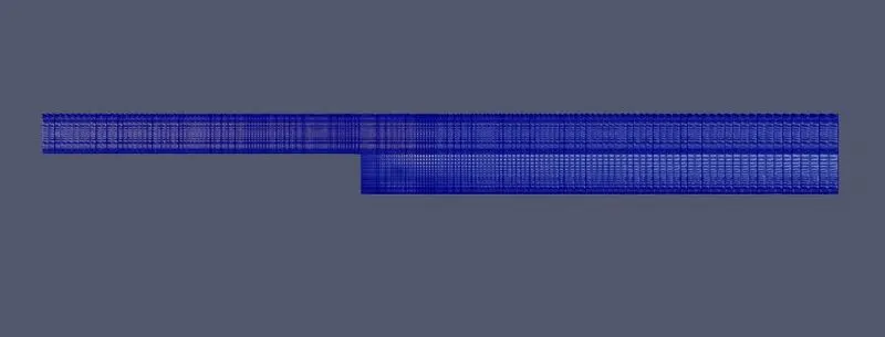
- Mesh when grading factor is 0.2:
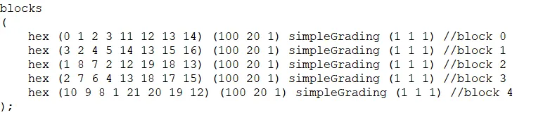
- Mesh when grading factor is 1:
- Now , the controlDict file in the system folder needs to be edited. It contains the start and end time of the solution with a solution interval time where solution during thr simulation is recorded for evry specified interval of time. Since the total length of the domain is 0.2m and the initial velocity is 0.01, the appropriate time period for the simulation can be determined from the distance and velocity relation and is calculated to be 20 seconds.
controlDict file:
/*--------------------------------*- C++ -*----------------------------------*\
  =========                 |
  \\      /  F ield         | OpenFOAM: The Open Source CFD Toolbox
   \\    /   O peration     | Website:  https://openfoam.org
    \\  /    A nd           | Version:  7
     \\/     M anipulation  |
\*---------------------------------------------------------------------------*/
FoamFile
{
    version     2.0;
    format      ascii;
    class       dictionary;
    location    "system";
    object      controlDict;
}
// * * * * * * * * * * * * * * * * * * * * * * * * * * * * * * * * * * * * * //

application     icoFoam;

startFrom       startTime;

startTime       0;

stopAt          endTime;

endTime         20;

deltaT          1e-2;

writeControl    timeStep;

writeInterval   20;

purgeWrite      0;

writeFormat     ascii;

writePrecision  6;

writeCompression off;

timeFormat      general;

timePrecision   6;

runTimeModifiable true;


// ************************************************************************* //
The total number of time steps is obtained by dividing the time period by the time steps. The selection of time step should be in such a way that the number of cycles is lesser so that the simulation is completed in less time or the simulations take more time to complete. Hence, greater deltaT (time step) value is taken (1e-2) and it is also very important to note the effect of time step on courant number. It must be kept below 1 so that the simulation converges to get a stable solution.
- The fvscheme and fvsolution files contain the numerical schemes and the solution procedures.The constant folder contains the mesh file (polymesh) and the physical properties (kinematic viscosity in this case).
- The defined mesh is structured by the 'blockMesh' command and the same will be stored in the constant/polymesh folder. The mesh structured is checked valid using 'checkMesh' command.
- The initial values (velocity and pressure) are stored in the '0' directory. These are the initial values of pressure and velocity at time = zero.
Velocity file:
/*--------------------------------*- C++ -*----------------------------------*\
  =========                 |
  \\      /  F ield         | OpenFOAM: The Open Source CFD Toolbox
   \\    /   O peration     | Website:  https://openfoam.org
    \\  /    A nd           | Version:  7
     \\/     M anipulation  |
\*---------------------------------------------------------------------------*/
FoamFile
{
    version     2.0;
    format      ascii;
    class       volVectorField;
    object      U;
}
// * * * * * * * * * * * * * * * * * * * * * * * * * * * * * * * * * * * * * //

dimensions      [0 1 -1 0 0 0 0];

internalField   uniform (0.01 0 0);

boundaryField
{
    inlet
    {
        type            fixedValue;
        value           uniform (0.01 0 0); //Dirichlet
    }

    outlet
    {
        type            zeroGradient;  //Neumann
    }

    walls
    {
        type           noSlip;
    }
}

// ************************************************************************* //
The velocity at the inlet is assumed to be 0.01m/s and is a Dirchlet boundary condition. The velocity at the outlet is calculated as a function of timesteps. As time step progresses, the velcoity at the outlet can be determined using the time marching values from the inlet velocity and hence the initial value of outlet velocity is defiend as ZeroGradient(Neumann bc). As per the boundary layer theory, the velocity of the fluid near the walls are negligible or zero and is a noslip condition.
Pressure file:
/*--------------------------------*- C++ -*----------------------------------*\
  =========                 |
  \\      /  F ield         | OpenFOAM: The Open Source CFD Toolbox
   \\    /   O peration     | Website:  https://openfoam.org
    \\  /    A nd           | Version:  7
     \\/     M anipulation  |
\*---------------------------------------------------------------------------*/
FoamFile
{
    version     2.0;
    format      ascii;
    class       volScalarField;
    object      p;
}
// * * * * * * * * * * * * * * * * * * * * * * * * * * * * * * * * * * * * * //

dimensions      [0 2 -2 0 0 0 0];

internalField   uniform 0;

boundaryField
{
    inlet
    {
        type            zeroGradient;  //Neumann
    }

    outlet
    {
        type            fixedValue;
        value           uniform 0;
    }

    walls
    {
        type            zeroGradient; //Neumann
    }
}

// ************************************************************************* //
Here, for pressure, at the inlet, the pressure contrary to velocity is a Neumann boundary condition and is given as ZeroGradient while at the outlet, the pressure at 1atm is defined as 'uniform 0'(Dirichlet bc). The pressure at the wall boundary is calculated as a function of time as the simulation undergoes (Neumann bc) and is defined as ZeroGradient.
- The simulation is then run using the transient solver 'icoFoam' and the results are post-processed and visualised using Paraview.
Results:
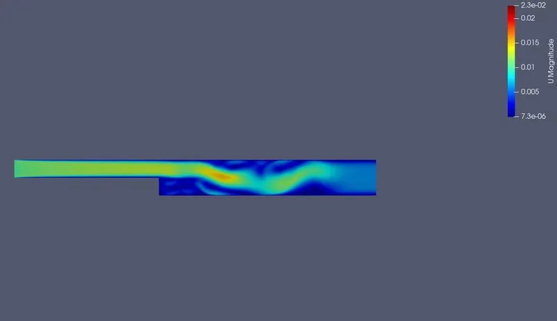
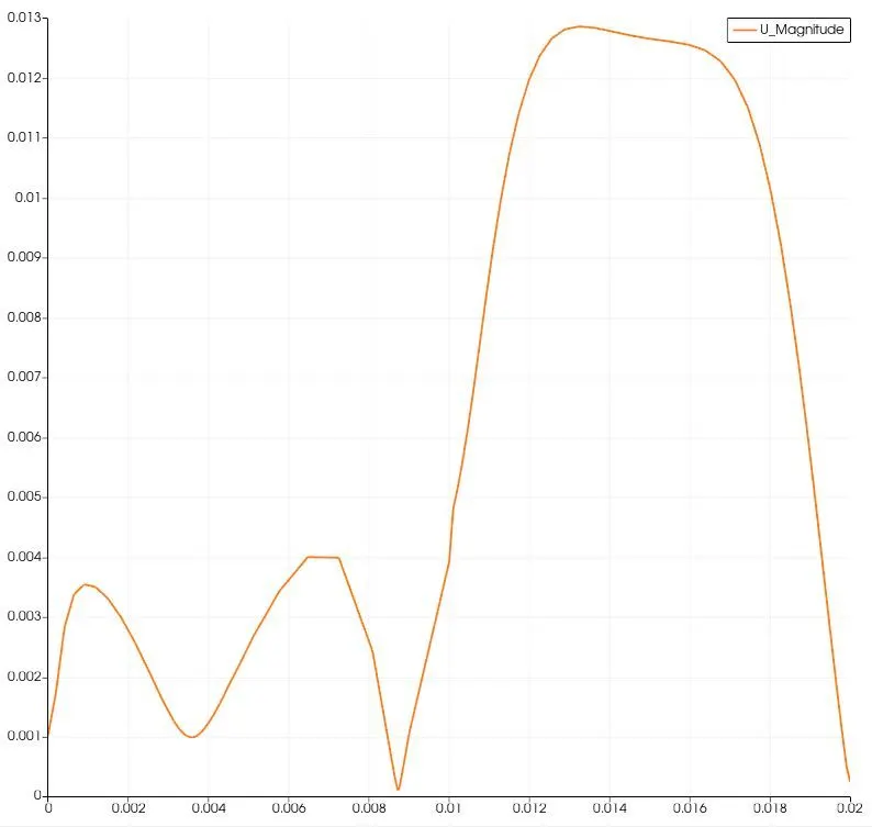
- When gradient factor is 0.2:
- Without grading factor:
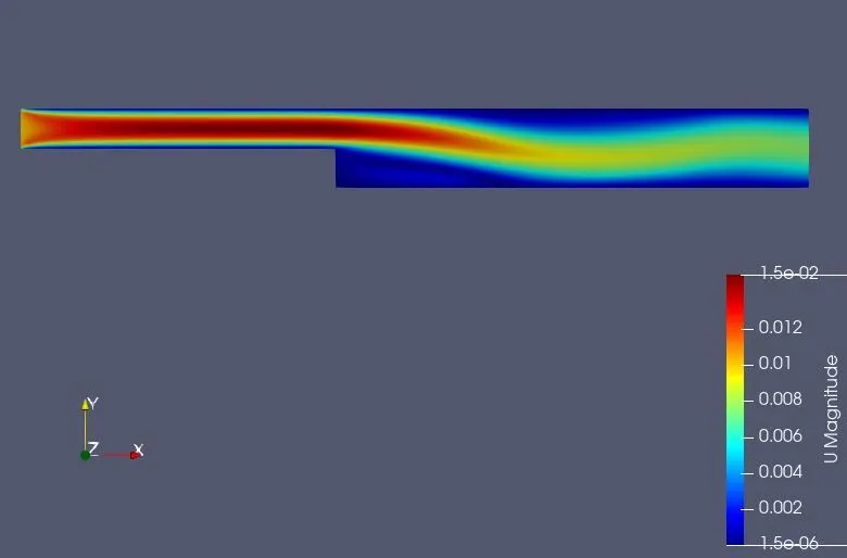
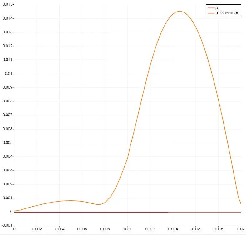
From both the results, it can be observed that the accurate and more relaible results are obtained from the refined mesh geometry. The mesh is refined more when a grading factor of 0.2 is input. Also, the residual formation during the iteration is lesser when there is a grading. The proper boundary layer seperation is depicted in the case of graded mesh and it shows a reliable physics. The laminar flow soon after the step becomes turbulent and forms vorteces, undergoes unprecedented changes in velocity and the same is depicted accurately in the graph obtained from graded mesh. The graded mesh shows that the cells at the boundary are finer, that is, control volumes are made smaller to compute more accurate values of quantities.