Week 9 - Parametric study on Gate valve.
Introduction:
A gate valve is generally used to completely shut off fluid flow when the gate disc is fully closed and when fully open position, provides full flow in a pipeline. We can control the flow rate by changing the position of the gate disc. A gate valve consists of a valve body, seat and disc, a spindle, gland, and a wheel for operating the valve.
Geometry:
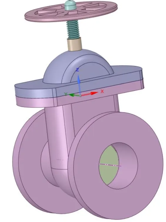
The geometry model of a gate valve is shown below:
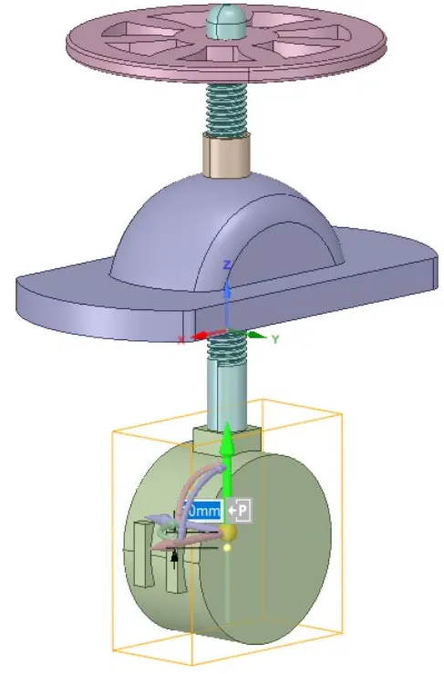
The inside view showing the gate disc (with the bottom part hidden) with 10mm lift is shown below.
For the parametric study, we have to click on 'P' on the gate disc and the group is created.
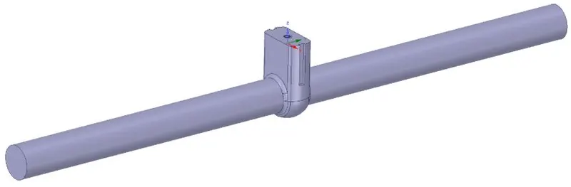
The fluid volume extract is shown with the inlet and outlet being pulled to 800mm each.
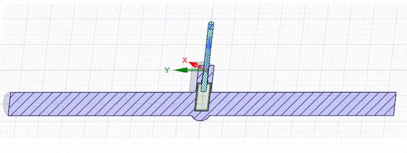
The cut section view of fluid volume extract is shown with the gate disc and spindle.
Meshing:
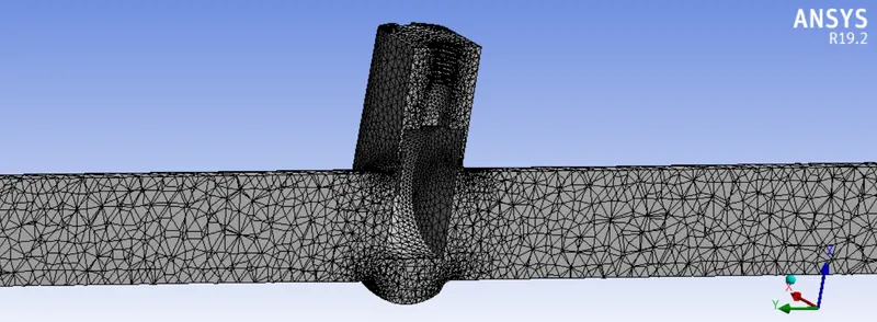
The unstructured meshing cut section view is done for the fluid volume extract as shown:
Element size: 9.28e-002 m
Max size: 0.185 m
Fluent settings:
Steady-state simulation
Gravity (z-axis) : -9.81 m/s
K-epsilon realizable - standard wall function
Inlet- pressure inlet
outlet - pressure outlet
Results:
Case 1: 20mm
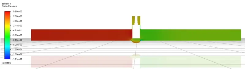
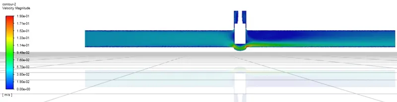
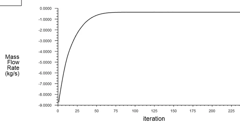
Case 2: 35mm
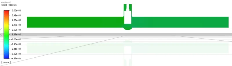
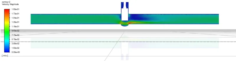
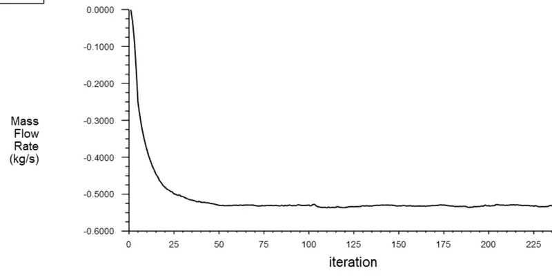
Case 3: 50 mm
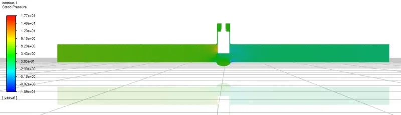
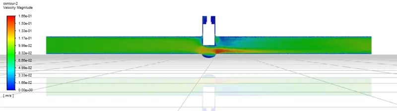
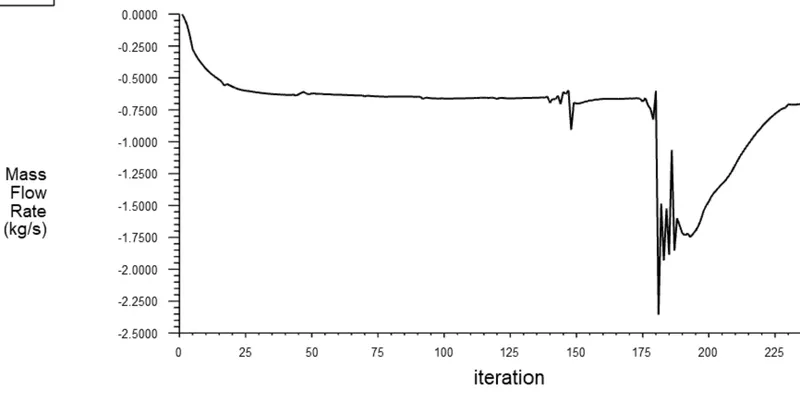
Case 4: 65 mm
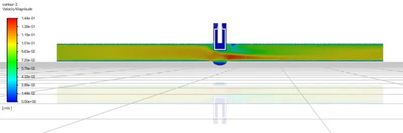
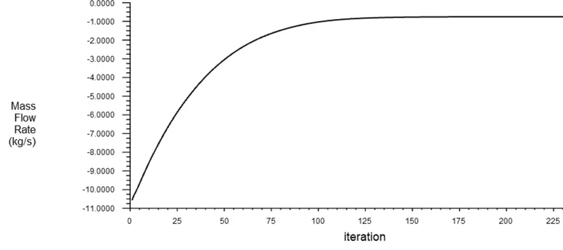
Case 5: 80 mm
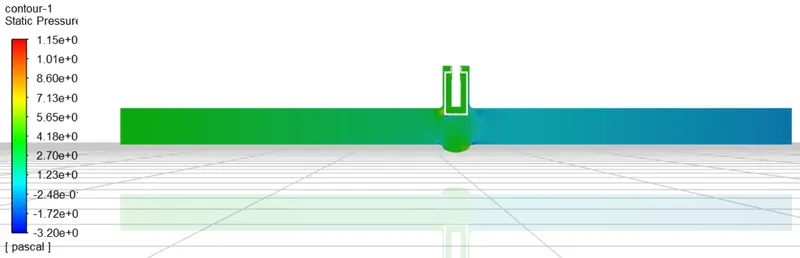
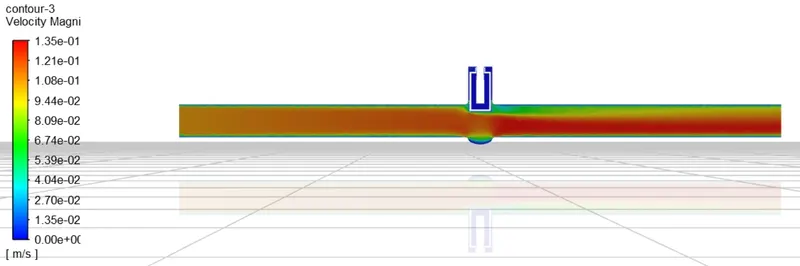
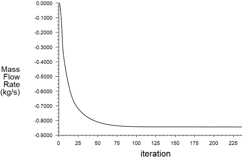
Q2 Calculate the flow coefficient and flow factor for each opening and plot the graph.
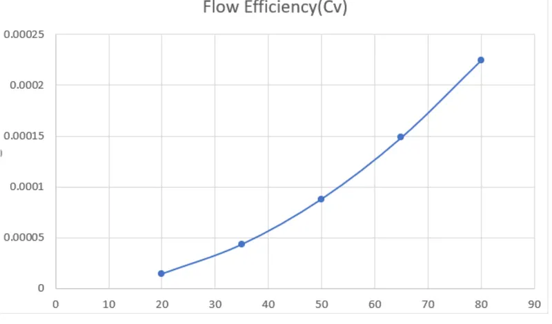
Ans. Flow coefficient:- The flow coefficient of a device is a relative measure of its efficiency at allowing fluid flow. It describes the relationship between the pressure drop across an orifice valve or other assembly and the corresponding flow rate.
Mathematically, the flow coefficient Cv (or flow capacity rating of the valve) can be expressed as
Cv = rate of flow*sqrt(specific gravity/pressure drop)
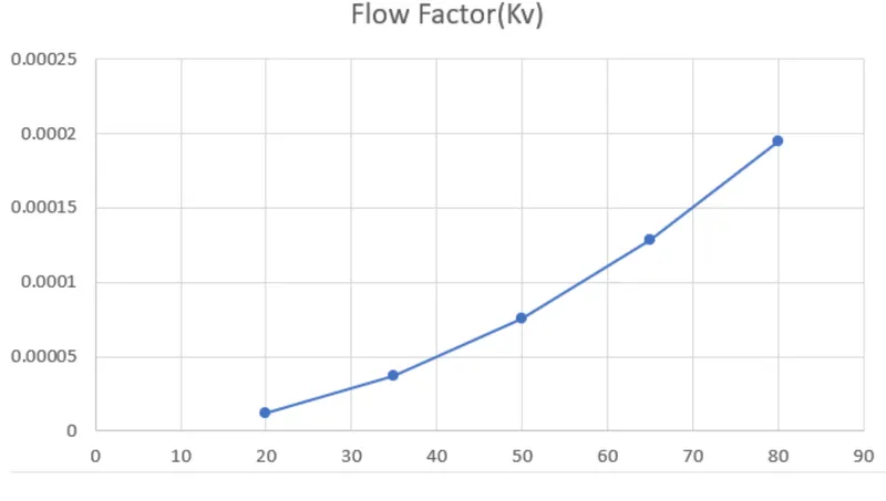
Flow Factor:- Kv can be calculated from Cv using the equations
Kv = 0.865*Cv
By using the above formula I calculated the flow coefficient and flow factor as given below-given quantities are:
The specific gravity of water = 1
Pressure drop = 10 Pa
Velocity = 0.1415488 m/s
For CASE 1,
Inlet diameter = (100 - 20) = 80 mm = 0.08 m
Area = pi*radius^2 = 3.14*0.04*0.04 = 0.005024 m^2.
Flow rate = Q = Area*velocity = 0.005024*0.1415488 = 0.000711 m^3/sec
Flow Coefficient : Cv = 0.0.000711 * sqrt(1/10) = 0.00022486.
Flow factor : Kv = 0.865 * 0.000224867 = 0.000194509 .
For CASE 2,
Inlet diameter = (100-35) = 65 mm = 0.065 m
Area = pi * radius^2 = 3.14*0.0325*0.0325 = 0.00332 m^2.
Flow rate = Q = Area*velocity = 0.00332*0.1415488 = 0.000469464 m^3/sec
Flow coefficient = Cv = 0.000469464 *sqrt(1/10) = 0.00014857.
Flow factor = Kv = 0.865*Cv = 0.000128415 .
For CASE 3,
Inlet diameter = (100-50) = 50mm = 0.05 m
Area = pi*radius^2 = 3.14*0.025*0.025 = 0.0019625 m^2
Flow rate = Q = Area*velocity = 0.0019625*0.1415488 = 0.000277789 m^3/sec
Flow coefficient = Cv = 0.000277789*sqrt(1/10) = 0.00008784.
Flow factor = Kv = 0.865*Cv = 0.00007599
For CASE 4,
Inlet diameter = (100-65) = 35 mm = 0.035 m
Area = pi*radius^2 = 3.14*0.0175*0.0175 = 0.00096163 m^2
Flow rate =Q = Area*velocity = 0.00096163*0.1415488 = 0.00013612 m^3/sec
Flow coefficient = Cv = 0.00013612*sqrt(1/10) = 0.00004304 .
Flow factor =Kv = 0.865*Cv = 0.00003723 .
For CASE 5,
Inlet diameter = (100-80) = 20mm = 0.02m
Area = pi*radius^2 = 3.14*0.01*0.01 = 0.000314 m^2
Flow rate = Q = Area*velocity = 0.000314*0.1415488 = 0.0000444 m^3/sec
Flow coefficient = Cv = 0.0000444*sqrt(1/10) = 0.000014
Flow factor = Kv = 0865*Cv = 0.000012 .
Plots:
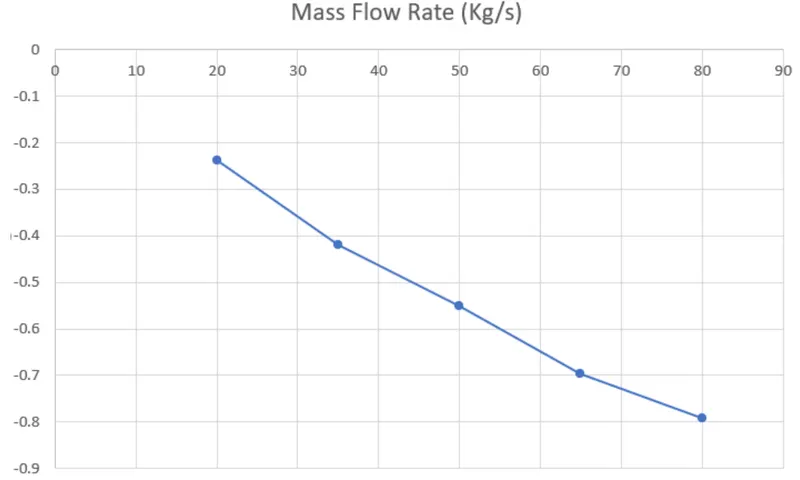
1. Mass flow rate vs disc position
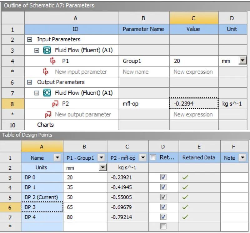
Actually, the mass flow rate is increasing (-ve sign represents outflow).
2. Flow coefficient vs disc position
3. Flow factor vs disc position
The parametric study showing the different design points and mass flow rates at outlet in Ansys:
Conclusion:
Mass flow rate magnitude increases (-ve flow rate shows the outflow) with the increased gate disc opening as more fluid is allowed to flow. Also with the increase in gate disc opening flow rate and flow coefficient also increases and are calculated using the above relations.
A parametric study is used for the simulation due to which we need not create different geometries and meshes for different cases, so parametric study saves a lot of time and gave us the required results.
FILE LINK: https://drive.google.com/file/d/1S-xYeBLfuawole0VauaaumlwdPBytq1b/view?usp=sharing