Week 10 - Simulating Combustion of Natural Gas.
Combustion model for CFD analysis
CFD modeling of combustion calls upon the proper selection and implementation of model suitable to faithfully represent the complex physical and chemical phenomenon associated with any combustion process. The model should be competent enough to deliver information related to the species concentration, their volumetric generation or destruction rate and changes in the parameters of the system like enthalpy, temperature and mixture density.
Combustion simulation in Ansys fluent
1. Non-premixed combustion
- In non-premixed combustion, fuel and oxidizer enter the reaction zone in distinct streams.
- It occurs during injection or late injection of fuel in IC engines.
- Examples of non-premixed combustion includes diesel IC engines, pulvarized coal furnaces and pool fires.
2. Premixed combustion
- In premixed combustion, fuel and oxidizer are mixed at the molecular level prior to ignition.
- Combustion occurs as flames front propagating into the unburnt reactants.
- Examples of premixed combustion include aspirated internal combustion engines, lean-premixed gas turbine combustors and gas-leak explosions.
3. Partially premixed combustion
- Partially premixed combustion systems are premixed flames withnon-uniform fuel-oxidizer
- Such flames include premixed jets discharging into an inert atmosphere, lean premixed combustors with diffusion pilot flames and cooling air jets, imperfectly mixed inlets.
Combustion based on phase:
1. Fluid phase(volumetric reactions)- combustion takes place in the fluid region
2. Wall(surface reactions)- combustion takes place on the wall or a solid surface
3. Particles(surface reactions)- combustion takes place on the lagrangian particles. Combustion takes place on the lagrangian particles.
4. Porous region- combustion takes place ina porous region, the reactions in an after-treatment system is an example of combustion in the porous regions.
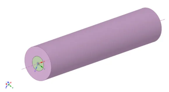
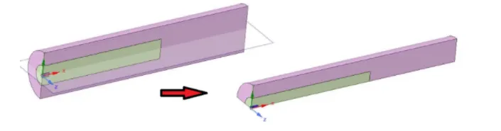
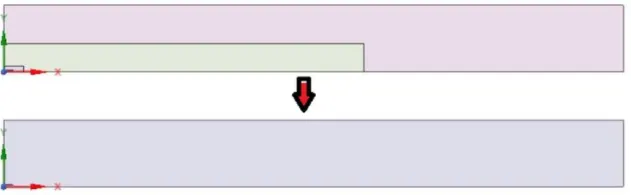
Geometry:
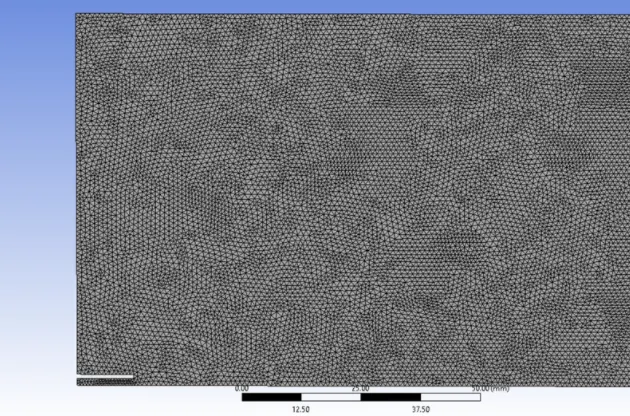
Meshing
Fluent setup:
Solver- Steady
Type- Pressure based
Turbulence model- Standard K-epsilon with standard wall functions
Energy model- ON
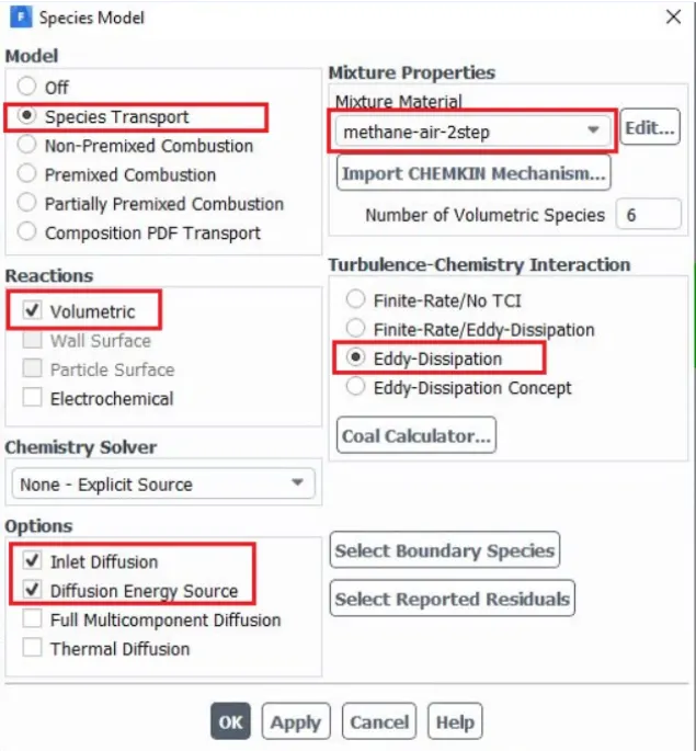
Species model:
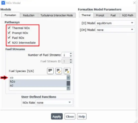
NOx model:
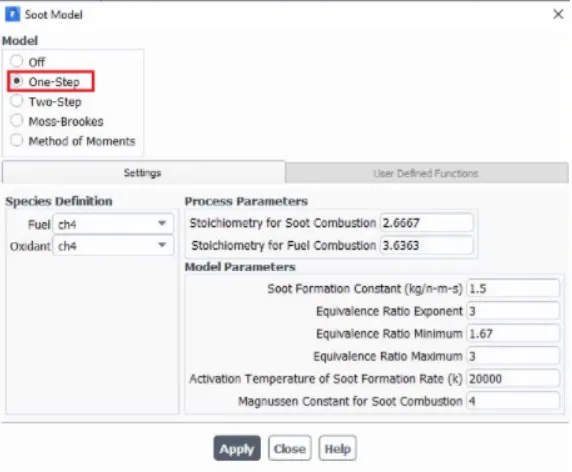
Soot model
Boundary conditions:
Air inlet: velocity =0.5 m/s, temp= 300 K
Species mass fraction CH4=0, O2=0.23, CO2=0, H2O=0
Fuel inlet: velocity =80 m/s, temp = 300 K
Species mass fraction CH4=1, O2=0, CO2=0, H2O=0
Outlet: Pressure: 0 pa
Solution method: SIMPLE
Results:
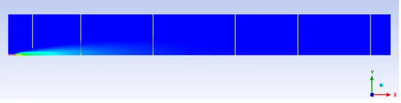
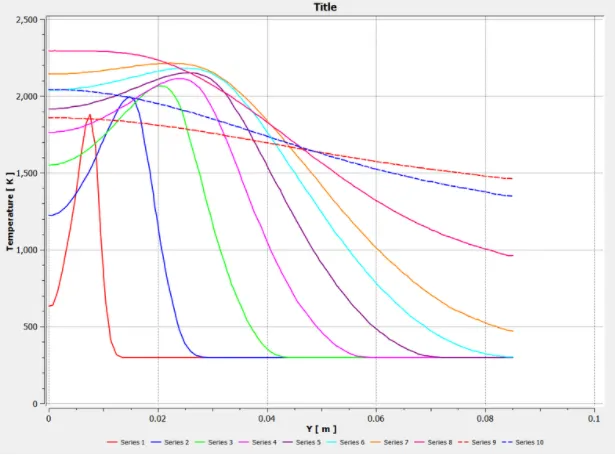
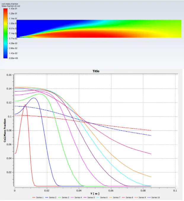
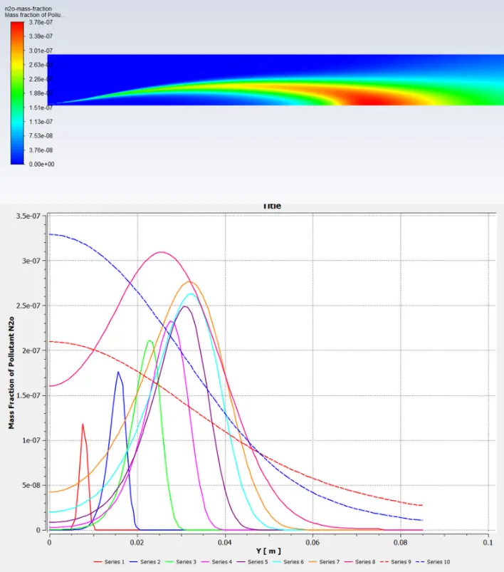
Line probes created to monitor the composition of the desired components during combustion along the burner width.
CASE 1: 100% CH4 nad 0% H2O
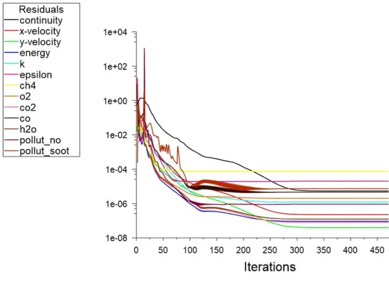
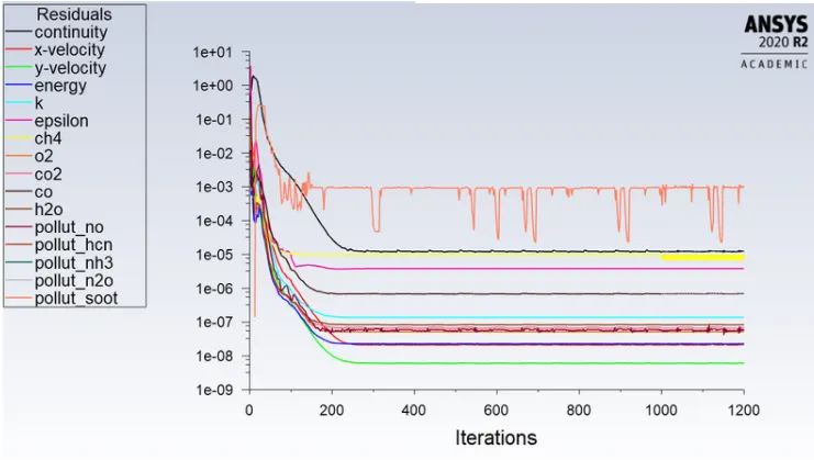
Residuals:
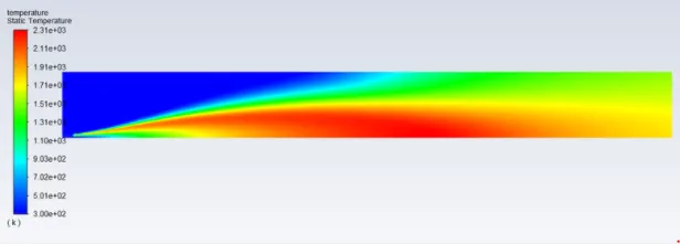
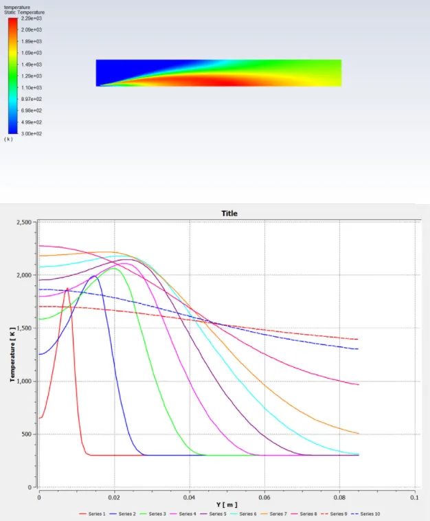
Temperature contour
CO2 contour and mass fraction
H2O contour and mass fraction
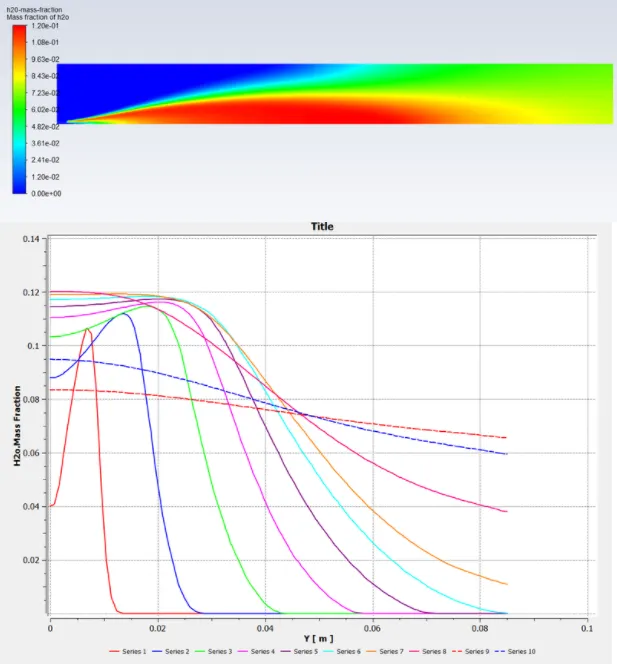
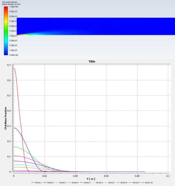
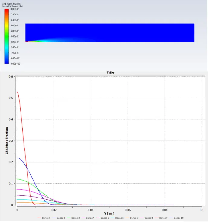
CH4 contour and mass fraction
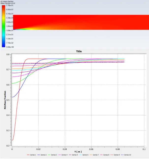
N2 contour and mass fraction
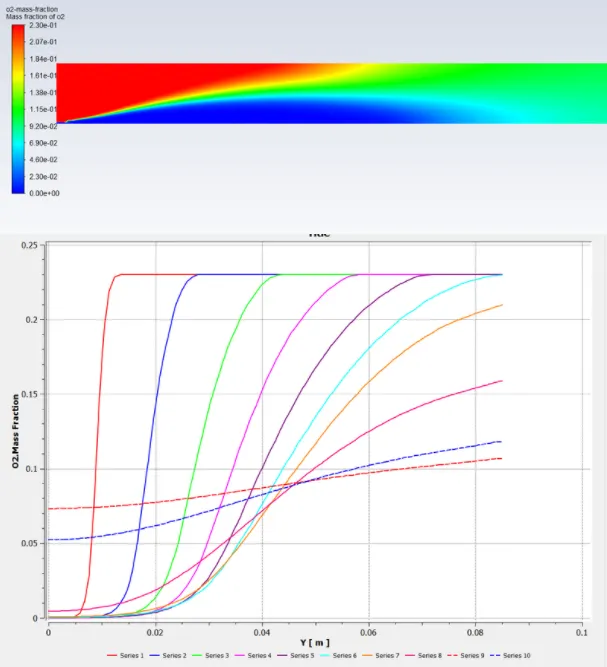
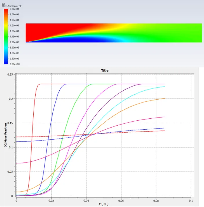
O2 contour and mass fraction
NO contour and mass fraction

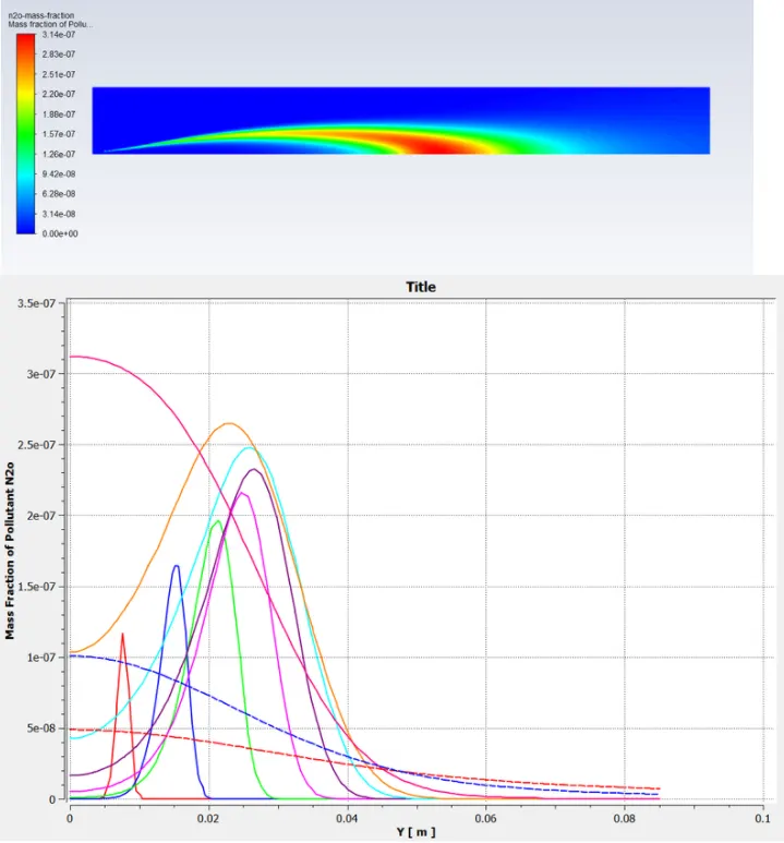
N2O contour and mass fraction
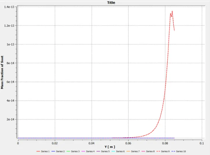
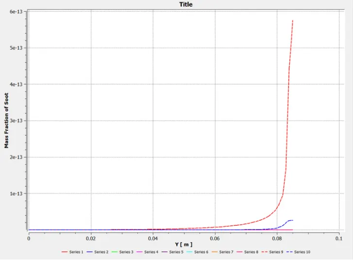
Soot mass fraction
CASE 2: 90% CH4 and 10% H2O
Temperature contour
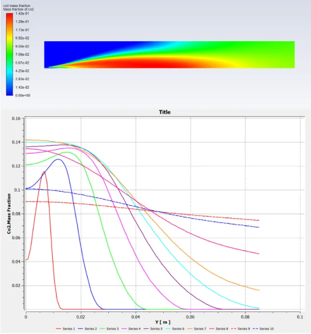
CO2 contour and mass fraction
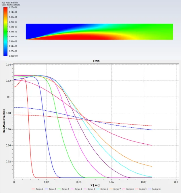
H2O contour and mass fraction
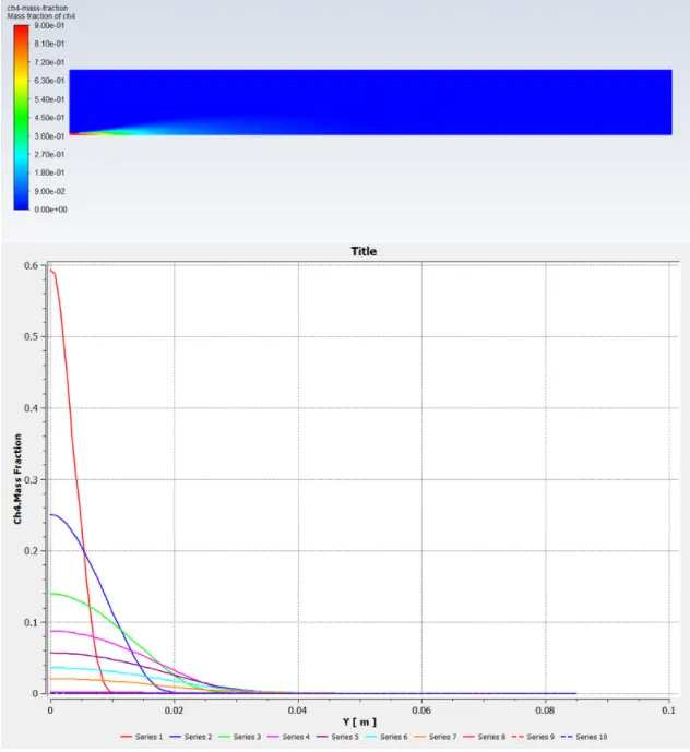
CH4 contour and mass fraction
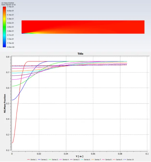
N2 contour and mass fraction
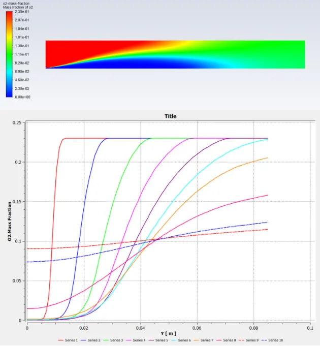
O2 contour and mass fraction
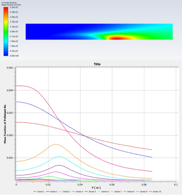
NO contour and mass fraction
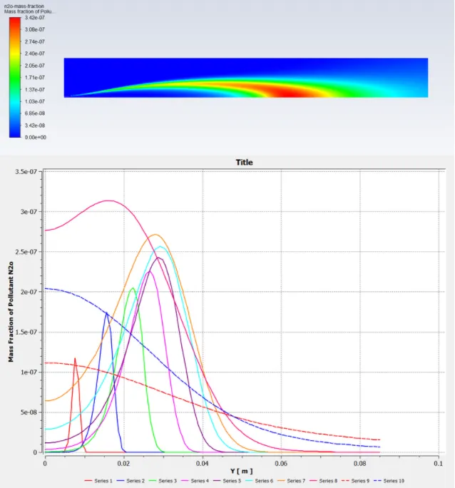
N2O contour and mass fraction
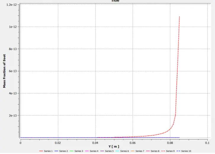
Case 3: 80% CH4 and 20% H2O
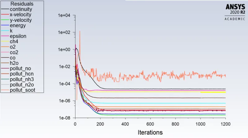
Residual
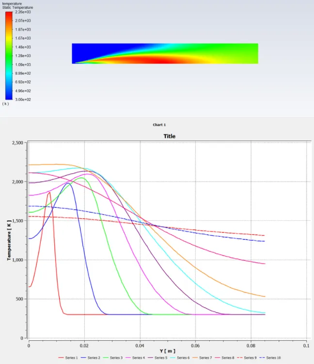
Temperature Contour
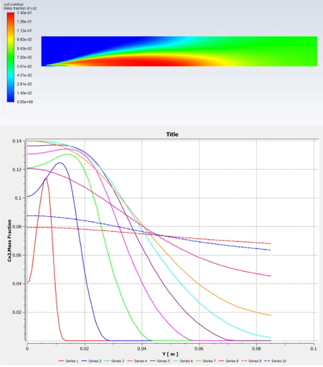
CO2 contour and mass fraction
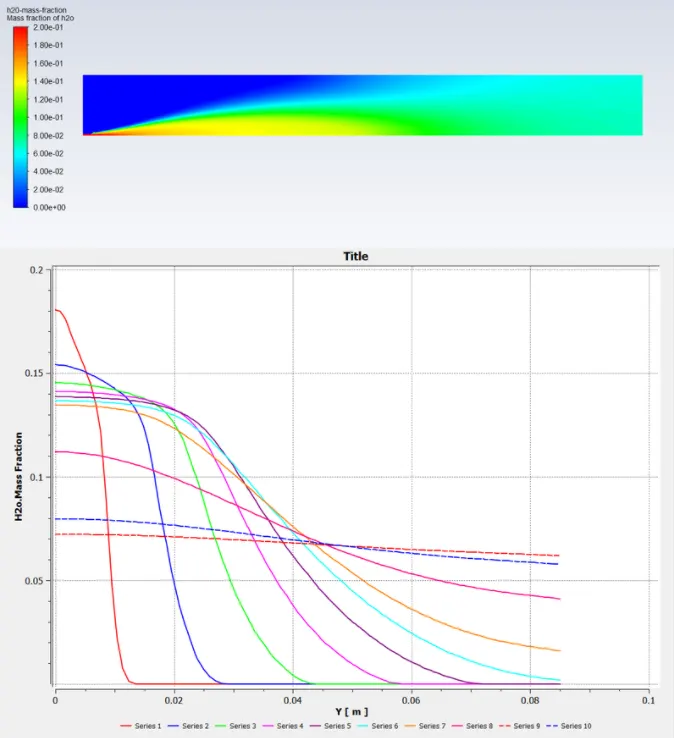
H2O contour and mass fraction
CH4 contour and mass fraction
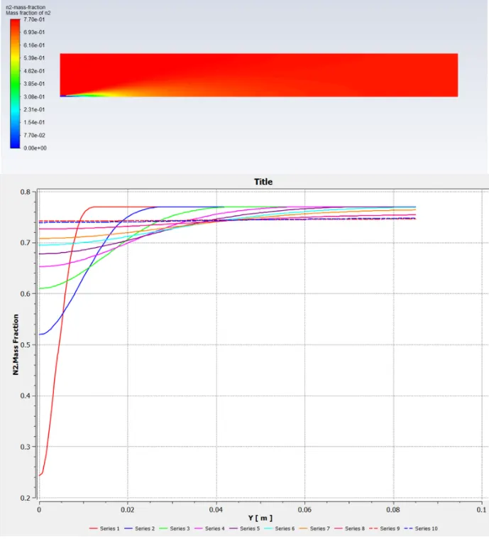
N2 contour and mass fraction
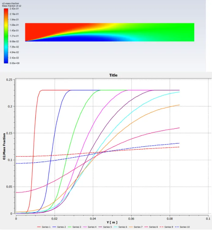
O2 contour and mass fraction
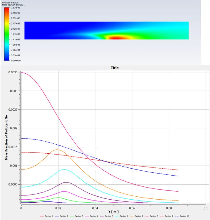
NO contour and mass fraction
N2O contour and mass fraction
Case 4: 70% CH4 and 30% H2O
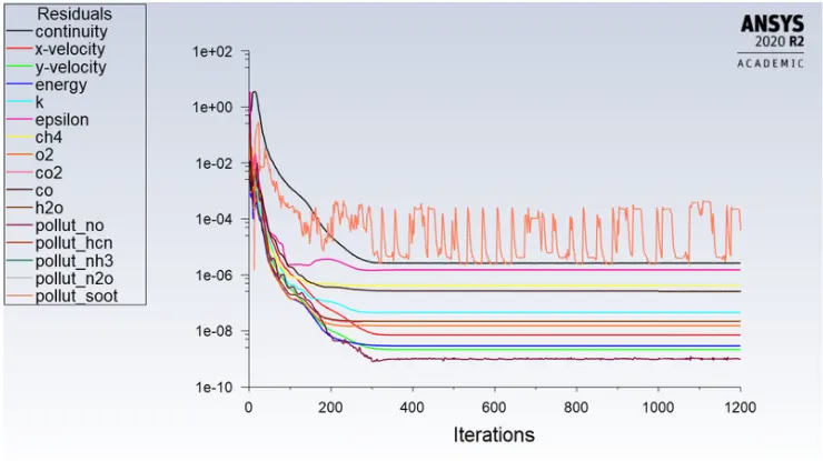
Residual
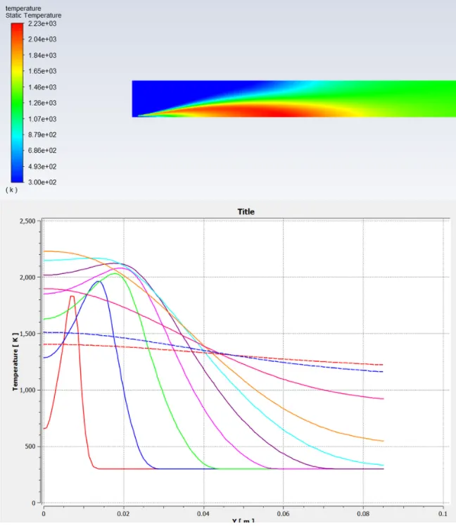
Temperature
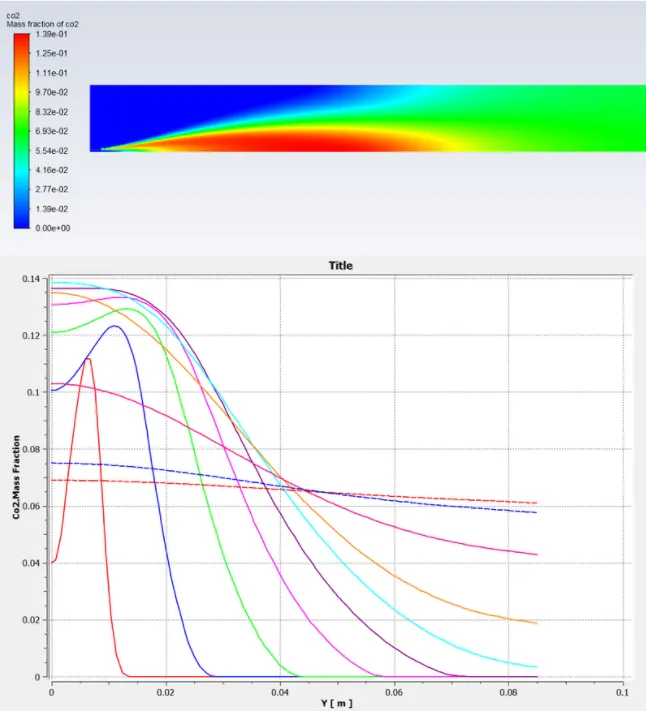
CO2 contour and mass fraction
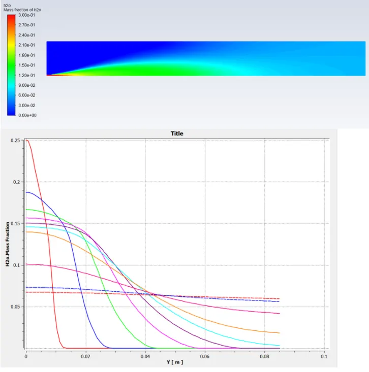
H2O contour and mass fraction
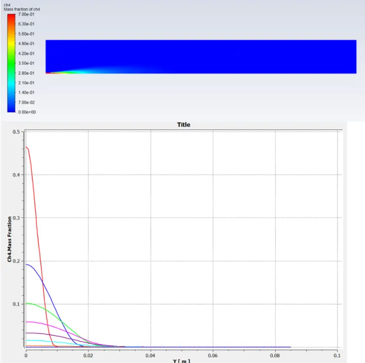
CH4 contour and mass fraction
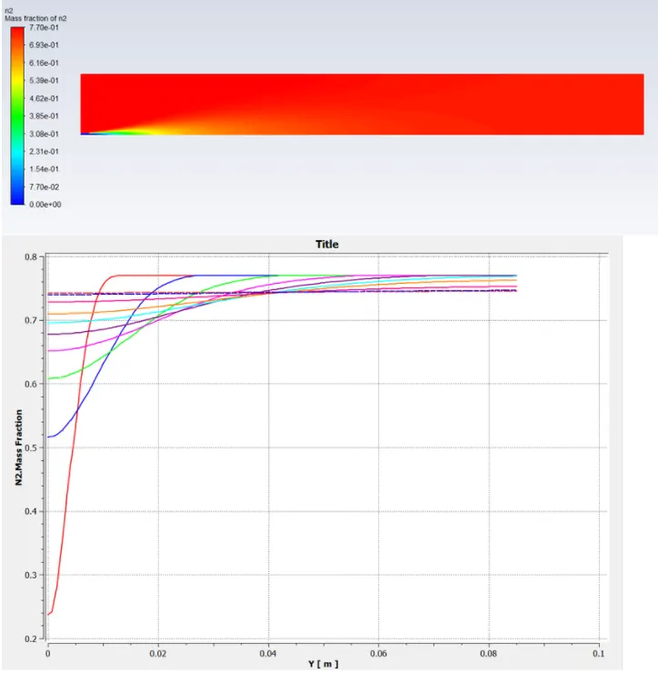
N2 contour and mass fraction
O2 contour and mass fraction
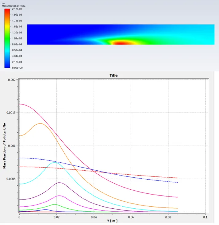
NO contour and mass fraction
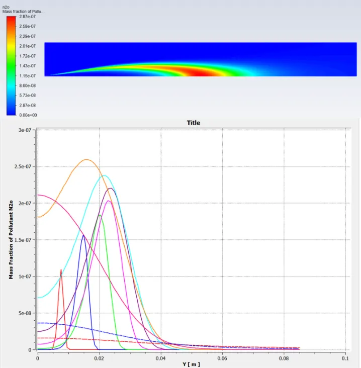
N2O contour and mass fraction
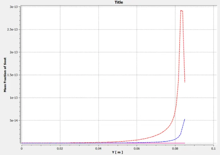
Conclusion and observations:
| Cases | Temperature | NO Mass Fraction | N2O Mass Fraction | Soot Mass Fraction |
| 1. 100% CH4 and 0% H2O | 2.32 e+03 | 7.74 e-07 | 3.78 e-07 | 1.06 e-11 |
| 2. 90% CH4 and 10% H2O | 2.29 e+03 | 5.34 e-07 | 3.41 e-07 | 4.18 e-12 |
| 3. 80% CH4 and 20% H2O | 2.25 e+03 | 3.49 e-07 | 3.12 e-07 | 2.81 e-12 |
| 4. 70% CH4 and 30% H2O | 2.22 e+03 | 2.19 e-07 | 2.89 e-07 | 1.54 e-12 |
A. As there is no ignition source for combustion the rate of reactions are comntrolled by turbulence mixing in eddy dissipation model. So with large eddy mixing time scale combustion starts when turbulence comes in picture.
B. As the water content in the fuel increases the formation of NOx and soot decreases and also the temperature decreases inside the chamber.
C. Adding water decreases the chemical reactions taking place hence reducing the temperature which leads to lower concentration of NOx.
D. CH4 burns completely as shown in the graphs but there are some unburnt carbon particles remaining in real world applications.
E. Soot formation takes place due to incomplete combustion of hydrocarbons.