Week 8 - Simulating Cyclone separator with Discrete Phase Modelling
Introduction:
A cyclone separator also called a cyclonic dust collector, is a widely used air pollution control device that cleanses flue gases of the particulate matter before such gases exit into the atmosphere. These devices are primarily labeled as pre-cleaners, as they are instrumental in removing large and abrasive particles from flue gases, which then go through additional filtration processes to remove fine particulate matter. The relevance of cyclone separators lies in the fact that they facilitate the first step of the flue gas filtration process. The objective of these devices is to minimize air pollution and environmental hazards caused by production plant exhaust.
Working principle:
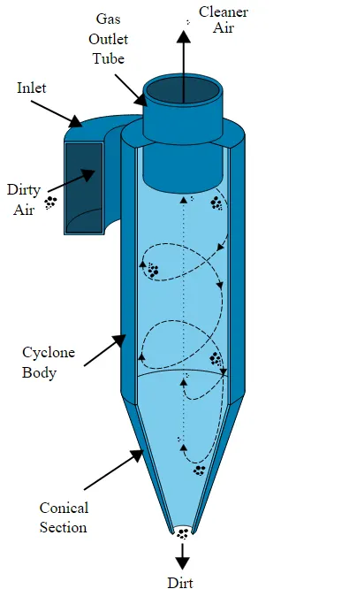
A high speed rotating (air)flow is established within a cylindrical or conical container called a cyclone. Air flows in a spiral pattern, beginning at the top (wide end) of the cyclone and ending at the bottom (narrow) end before exiting the cyclone in a straight stream through the center of the cyclone and out the top. Larger (denser) particles in the rotating stream have too much inertia to follow the tight curve of the stream and strike the outside wall, falling then to the bottom of the cyclone where they can be
removed. In a conical system, as the rotating flow moves towards the narrow end of the cyclone the rotational radius of the stream is reduced, separating smaller and smaller particles.
CYCLONE EFFICIENCY EMPIRICAL MODELS
1. Iozia and Leith Model
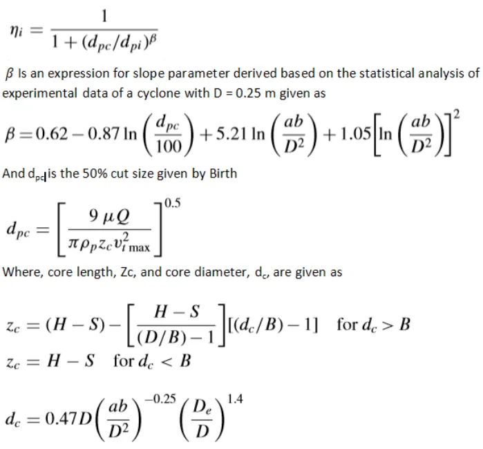
Iozia and Leith's logistic model is a modified version of the Barth Model, which is developed based on force balance.
The model assumes that a particle carried by the vortex endures the influence of two forces: a centrifugal force and flow resistance.
The collection efficiency i if particle diameter dpi can be calculated as:
2. Li and Wang Model
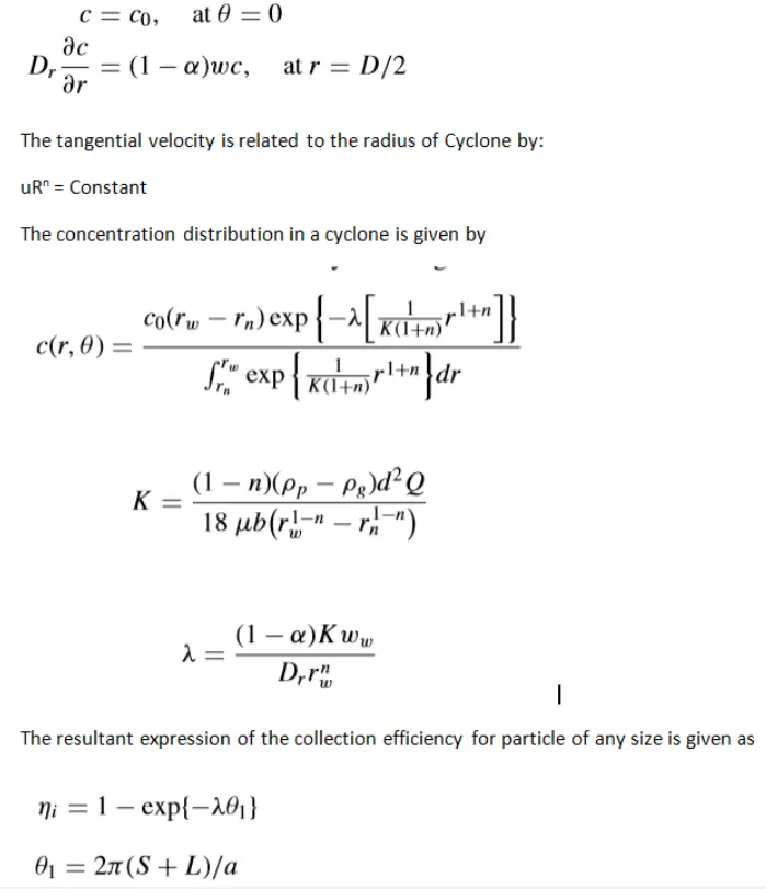
The Li and Wang model include particle bounce or re-entrainment and turbulent diffusion at the cyclone wall. A two-dimensional analytical expression of particle distribution in the cyclone is obtained. Li and Wang's model was developed based on the following assumptions:
• The radial particle velocity and the radial concentration of the profile is not constant for uncollected particles within the cyclone.
• Boundary conditions with the consideration of turbulent diffusion coefficient and particle bounce re-entrainment on the cyclone wall are:
3. Koch and Licht Model
Koch and Licht's collection theory recognized the inherently turbulent nature of cyclones and the distribution of gas residence times within the cyclone. Koch and Licht described particle motion in the entry and collection regions with the additional following assumptions:
• The tangential velocity of a particle is equal to the tangential velocity of the gas flow, i.e. there is no slip in the tangential direction between the particle and the gas.
• The tangential velocity is related to the radius of the cyclone by uRn = constant.
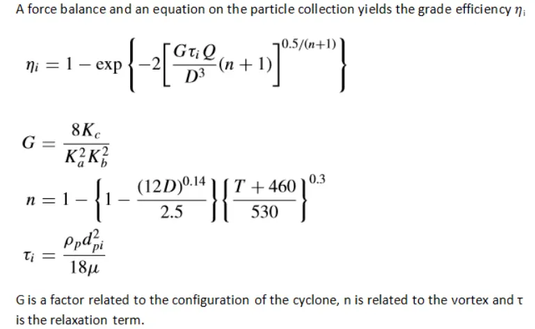
A force balance and an equation on the particles collection yields
the grade efficiency ni
4. Lapple Model
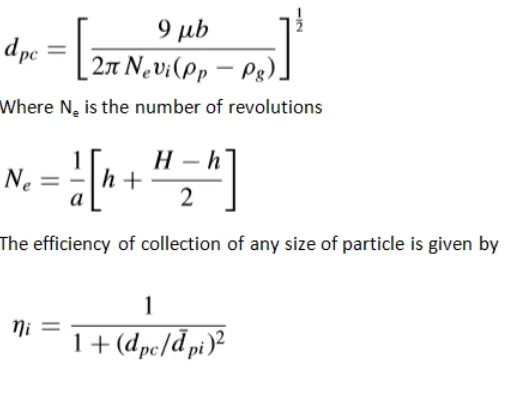
Lapple model was developed based on force balance without considering the flow resistance. Lapple assumed that a particle entering the cyclone is evenly distributed across the inlet opening. The particle that travels from inlet half-width to the wall in the cyclone is collected with 50% efficiency. The semi-empirical relationship developed by Lapple to calculate a 50% cut diameter, dpc, is
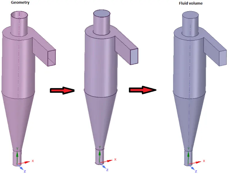
Geometry:
Mesh Settings:
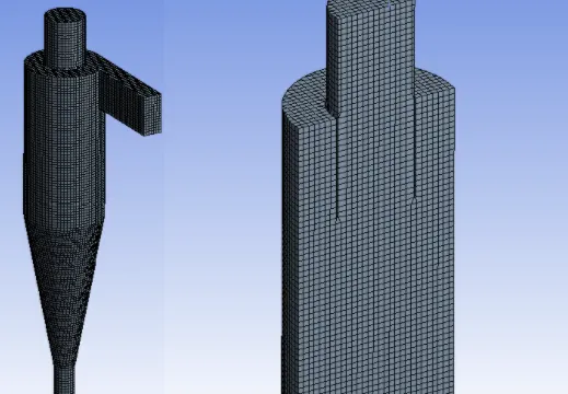
Cutcell meshing method is used to create the structured mesh for the fluid volume. Structured meshing always gives better results than unstructured.
The total number of elements is 64238 with a max size = 6.98e-003 m.
Boundary Conditions
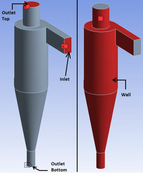
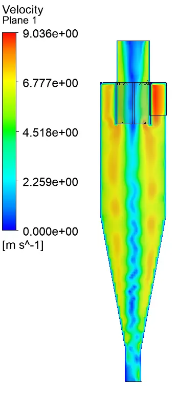
The inlet and outlets are shown in the figure
Fluent settings:
Pressure based solver
Steady State
Gravity in -Y direction
K-epsilon RNG, swirl-dominated flow, standard wall functions
DPM Settings:
Interaction with continuous phase
DPM Interation interval =10
Tracking parameter = 500000
Step length factor = 5
Particle type- Anthracite injection at inlet with given velocity and particle size based on the cases.
Separation Efficiency = No. of particles trapped / No. of particles tracked
Analysis on a given cyclone separator model by varying the particle diameter from 1 μm to 5 μm and velocity as 3m/sec, calculate the separation efficiency in each case.
a. 1 μm and 3m/s
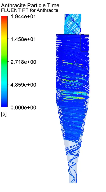
Separation Efficiency = 24/98 *100 = 24.48%
b. 2 μm and 3m/s
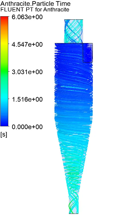
Separation Efficiency = 40/98 *100 = 40.81%
c. 3 μm and 3m/s
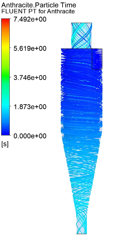
Separation Efficiency = 68/98 *100 = 69.38%
d. 4 μm and 3m/s
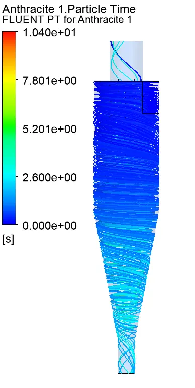
Separation Efficiency = 88/98 *100 = 89.79%
e. 5 μm and 3m/s
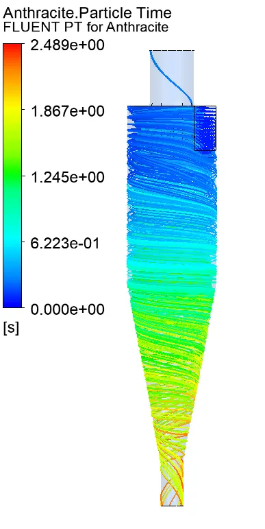
Separation Efficiency = 95/98 *100 = 96.94%
Analysis on a given cyclone separator model by varying the particle velocity from 1 m/sec to 5 m/sec and calculate the separation efficiency and pressure drop in each case. Discuss the results. [Use particle diameter size as 5 μm for all cases & keep flow velocity same as particle velocity]
A. 1 m/sec and 5 μm
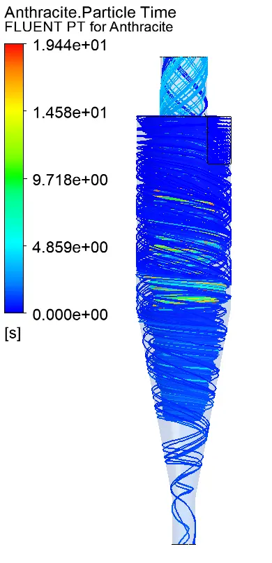
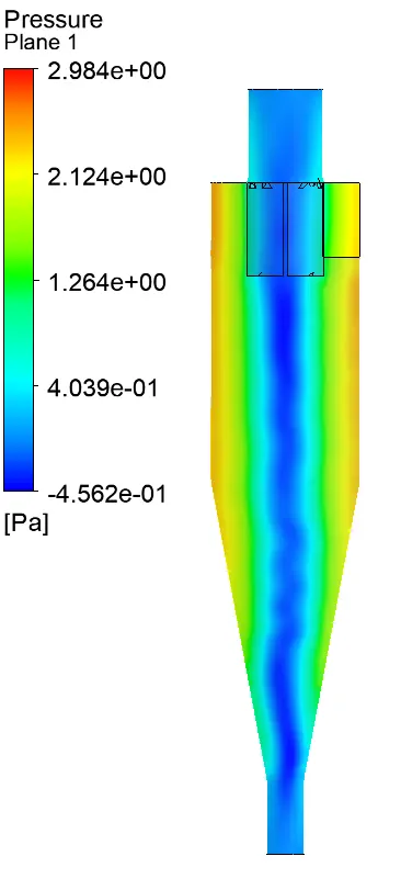
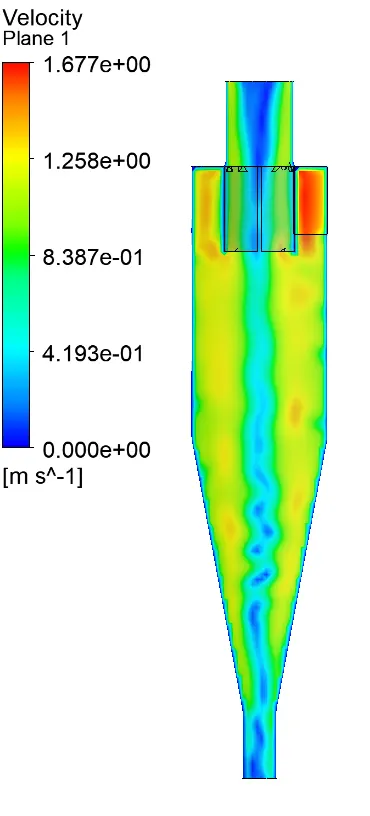
Separation Efficiency = 4/98 *100 = 4.08%
C. 3 m/sec and 5 μm
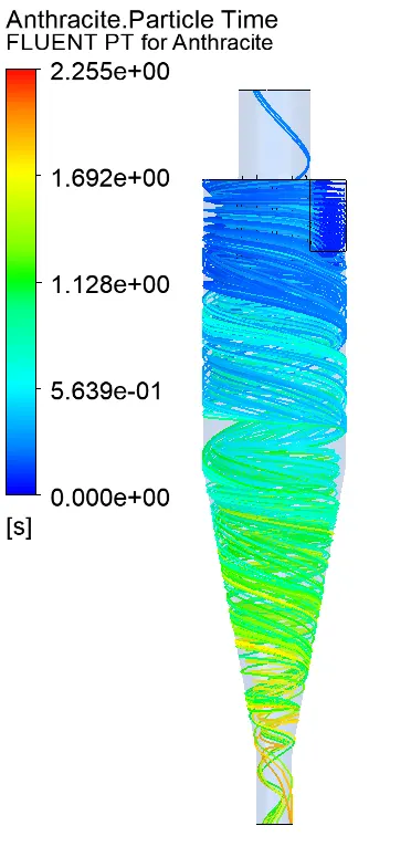
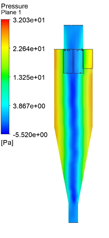
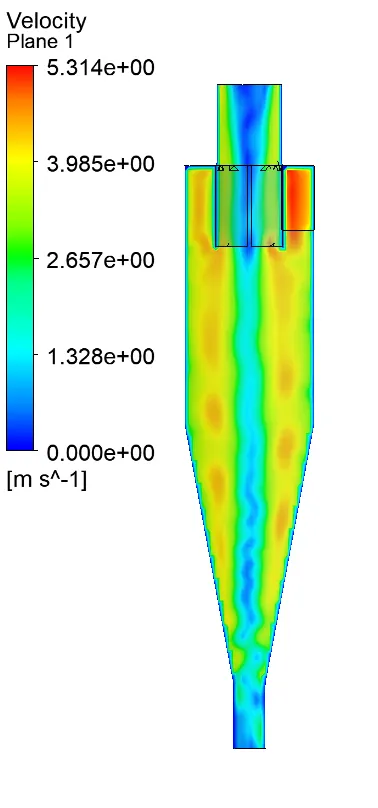
Separation Efficiency = 95/98 *100 = 96.94%
C. 4 m/sec and 5 μm
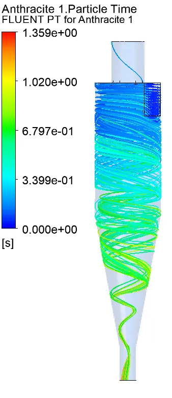
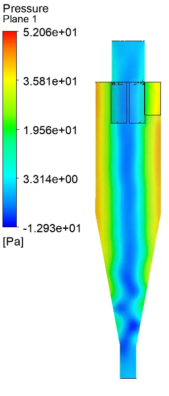
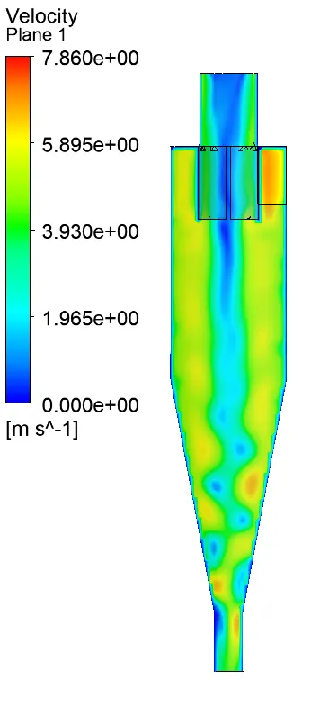
Separation Efficiency = 95/98 *100 = 96.94%
C. 5 m/sec and 5 μm
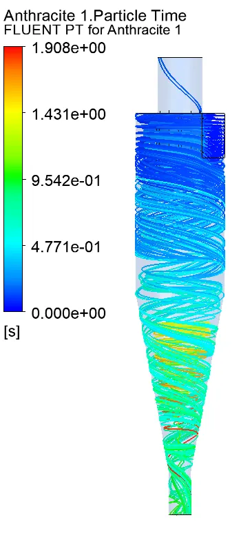
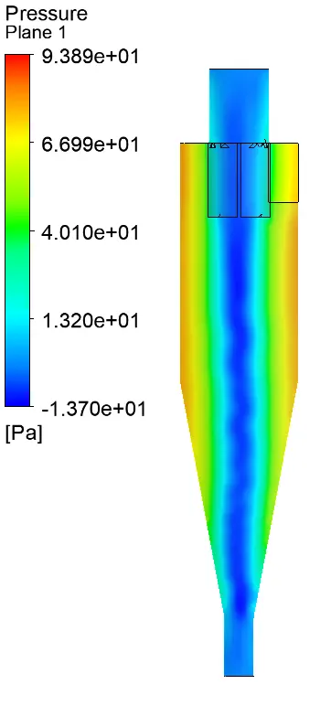
Separation Efficiency = 95/98 *100 = 96.94%
Results:
For same velocity and different particle size
| Cases | Particle size (m) |
Particle velocity (m/s) |
Particle tracked | Particle trapped | Particle escaped | Separation efficiency (%) | Pressure drop (Pa) |
| 1 | 1e-6 | 3 | 98 | 24 | 40 | 24.48 | 30.02 |
| 2 | 2e-6 | 3 | 98 | 40 | 33 | 40.81 | 30.02 |
| 3 | 3e-6 | 3 | 98 | 68 | 28 | 69.38 | 30.02 |
| 4 | 4e-6 | 3 | 98 | 88 | 6 | 89.79 | 30.02 |
| 5 | 5e-6 | 3 | 98 | 95 | 3 | 96.94 | 30.02 |
For different velocity and same particle size
| Cases | Particle size (m) |
Particle velocity (m/s) |
Particle tracked | Particle trapped | Particle escaped | Separation efficiency (%) | Pressure drop (Pa) |
| 1 | 5e-6 | 1 | 98 | 4 | 11 | 24.48 | 3.45 |
| 2 | 5e-6 | 2 | 98 | 26 | 33 | 40.81 | 14.32 |
| 3 | 5e-6 | 3 | 98 | 95 | 3 | 96.94 | 31.88 |
| 4 | 5e-6 | 4 | 98 | 95 | 3 | 96.94 | 55.54 |
| 5 | 5e-6 | 5 | 98 | 95 | 3 | 96.94 | 87.21 |
Conclusion
1. Separation efficiency in a cyclone separator depends on the velocity and the particle size.
2. Separation efficiency in a cyclone separator is directly proportional to velocity and pressure drop between inlet and outlet.
3. Particle resident time decreases with increase in particle size and velocity, thus increases the efficiency.