Week 9 - Parametric study on Gate valve.
PARAMETRIC STUDY ON GATE VALUE
AIM: To perform a parametric study on the gate valve simulation by setting the opening from 10 % to 80%.
OBJECTIVE:
- Obtain the mass flow rates at the outlet for each design point.
- Calculate the flow coefficient and flow factor for each opening and plot the graph.
- Discuss the results of the mass flow rate and flow coefficient.
THEORY:
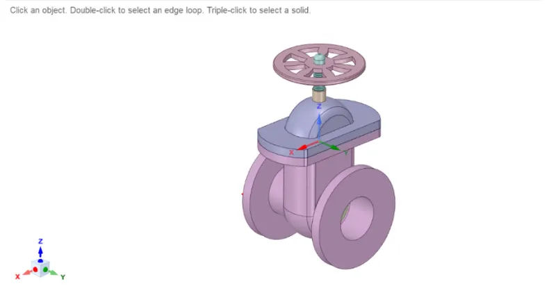
Gate valves work by inserting a rectangular gate or wedge into the path of a flowing fluid. They are operated by a threaded stem that connects the actuator (generally a hand wheel or motor) to the stem of the gate. If the valve has a rising stem its position can be seen just by looking at the position of the stem. A gate valve is used to control the fluid flow through lifting and descending the gate. A gate distinct feature is to provide an unobstructed passageway, which includes minimal pressure loss over the valve.
Flow factor:
The flow factor of a device is a relative measure of its efficiency at allowing fluid flow. It describes the relationship between the pressure drop across an orifice valve or other assembly and the corresponding flow rate.
Mathematically the flow factor `k_v`(or flow-capacity rating of valve) can be expressed as :
`k_v=Q((SG)/(DeltaP))^0.5`
where:
- Q is the rate of flow (expressed in `m^3/h`),
- SG is the specific gravity of the fluid (for water = 1),
- ΔP is the pressure drop across the valve (expressed in a bar).
Flow coefficient(`C_v`)
`c_v=1.1560*k_v`
SIMULATIONS AND SOLUTIONS:
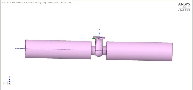
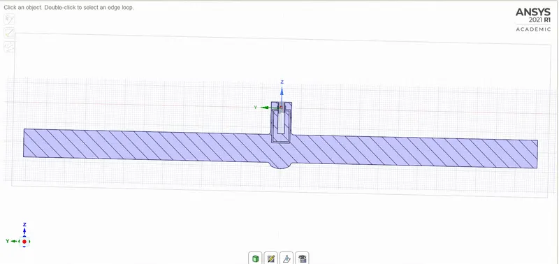
In this project, we have a total of 8 cases in which each case shows the flow of water through the gate valve with a release of 0.01m in each case.
Geometry:
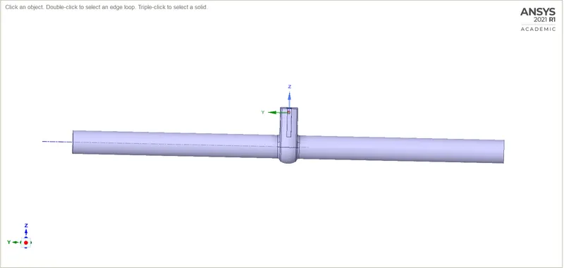
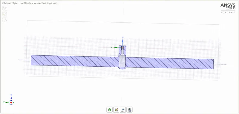
To the given geometry we move the gate valve up accordingly to each case, then pulling the sides of the extracted volume.
Case 1:
Case 2:
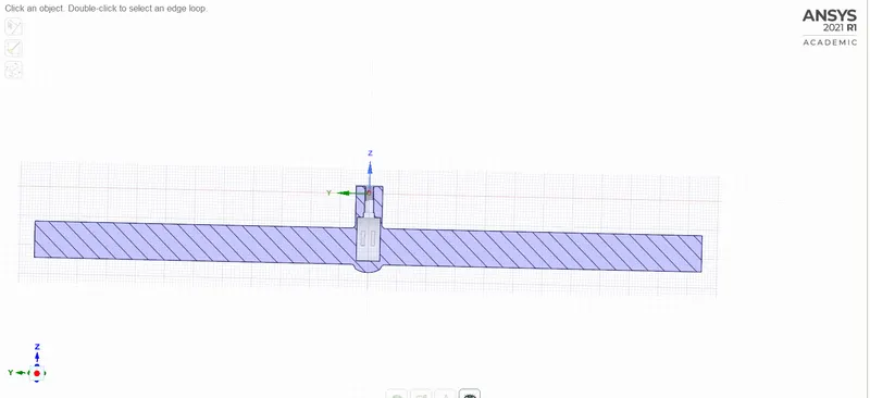
Case 3:
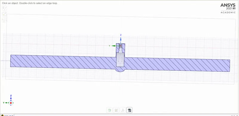
Case 4:
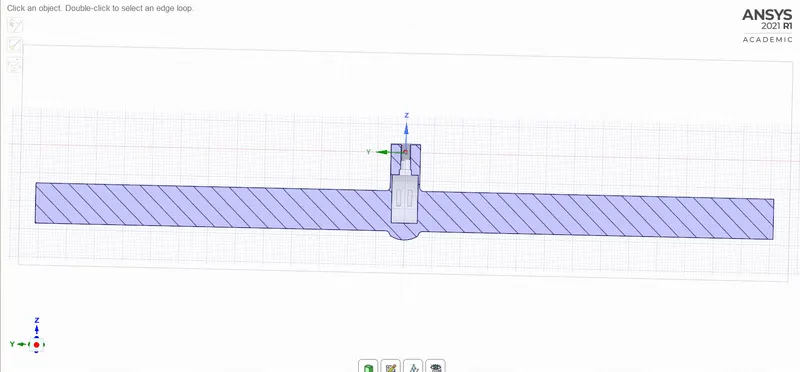
Case 5:
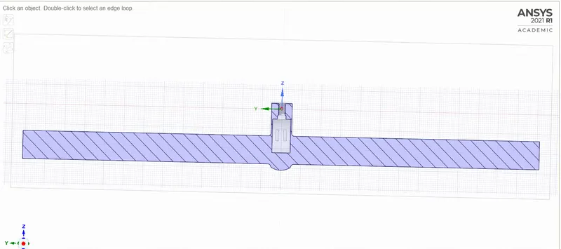
Case 6:
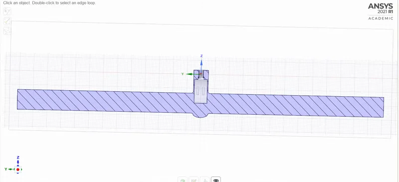
Case 7:
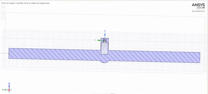
Case 8:
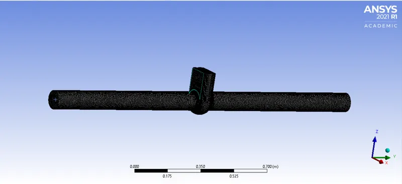
Meshing:
Mesh is the same for all the cases keeping the element size 0.0055m.
Simulations
CASE 1:
We have lifted the gate valve: 0.01.
Part 1:
|
SETUP |
||
|
Gravity |
-9.81 in the Z direction | |
|
Solver Type |
Pressure-Based |
|
|
Velocity Formulation |
Absolute |
|
|
Time |
|
|
|
Models |
Viscous model: K-epsilon, Realize, Scaled wall functions. Energy model: OFF |
|
|
Material |
Fluid type: Water Solid-type: Aluminium |
|
|
Cell zones |
Fluid type: water Solid: Al |
|
|
Boundaries |
Pressure Inlet: 10pa Wall:- wall Outlet:-Outlet pressure Volume: interior |
|
|
Reference values |
Standard |
|
|
Definitions |
Mass flow rate | |
|
Initialization |
Standard Starting from inlet |
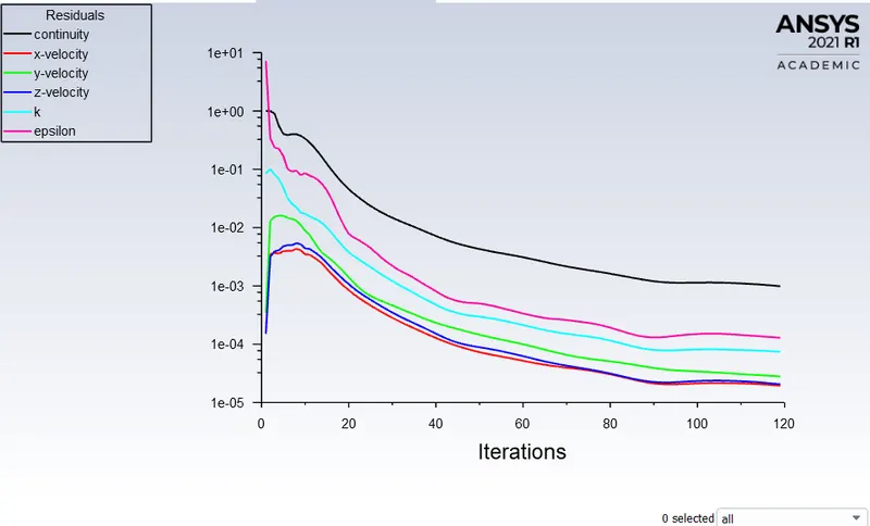
Residual plot:
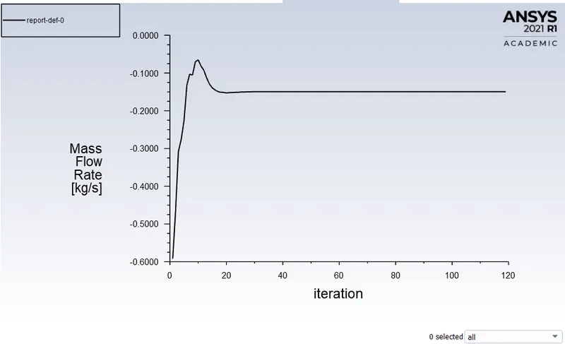
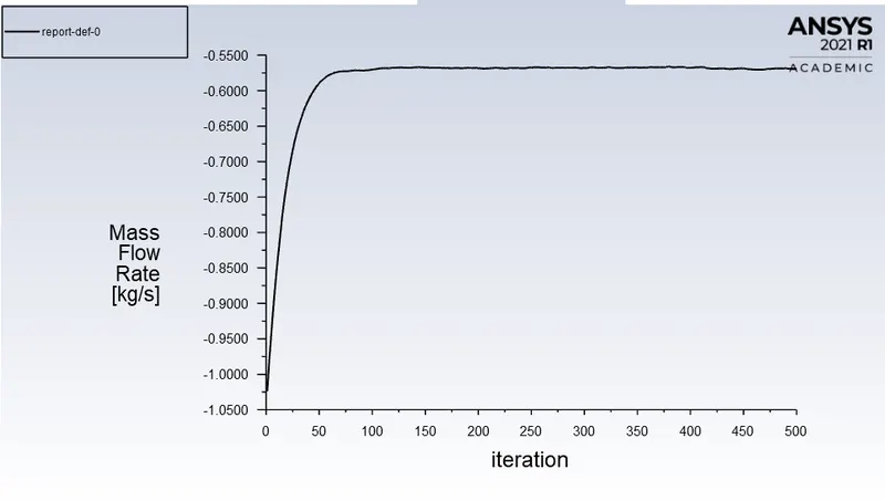
Mass flow rate:
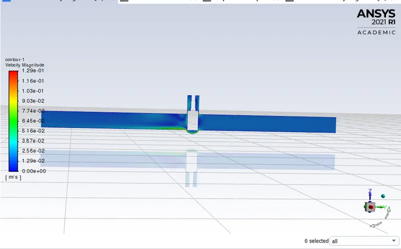
Velocity counter:
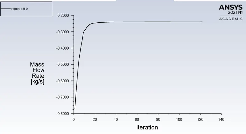
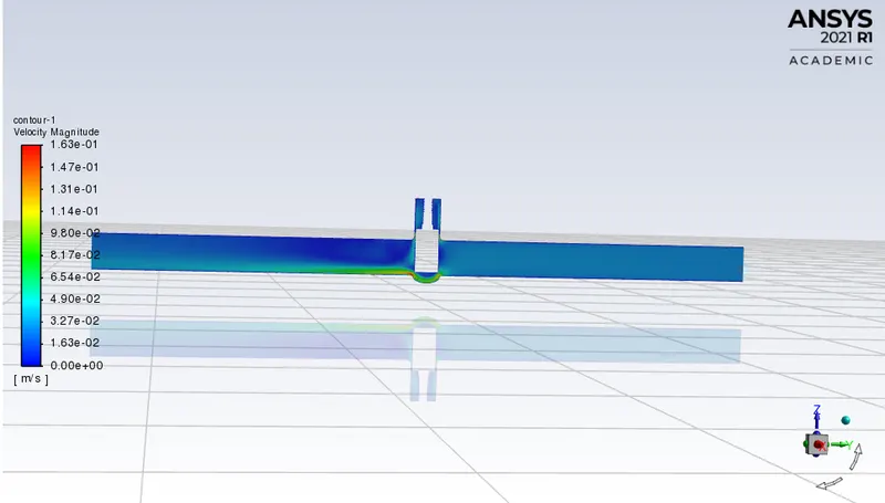
CASE 2:
We have lifted the gate valve: 0.02.
Part 1:
|
SETUP |
||
|
Gravity |
-9.81 in the Z direction | |
|
Solver Type |
Pressure-Based |
|
|
Velocity Formulation |
Absolute |
|
|
Time |
|
|
|
Models |
Viscous model: K-epsilon, Realize, Scaled wall functions. Energy model: OFF |
|
|
Material |
Fluid type: Water Solid-type: Aluminium |
|
|
Cell zones |
Fluid type: water Solid: Al |
|
|
Boundaries |
Pressure Inlet: 10pa Wall:- wall Outlet:-Outlet pressure Volume: interior |
|
|
Reference values |
Standard |
|
|
Definitions |
Mass flow rate | |
|
Initialization |
Standard Starting from inlet |
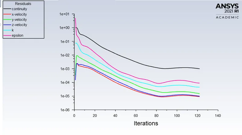
Residual plot:
Mass flow rate:
Velocity counter:
CASE 3:
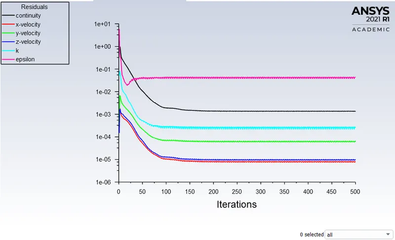
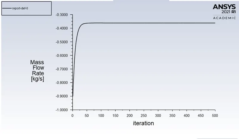
We have lifted the gate valve: 0.03.
Part 1:
|
SETUP |
||
|
Gravity |
-9.81 in the Z direction | |
|
Solver Type |
Pressure-Based |
|
|
Velocity Formulation |
Absolute |
|
|
Time |
|
|
|
Models |
Viscous model: K-epsilon, Realize, Scaled wall functions. Energy model: OFF |
|
|
Material |
Fluid type: Water Solid-type: Aluminium |
|
|
Cell zones |
Fluid type: water Solid: Al |
|
|
Boundaries |
Pressure Inlet: 10pa Wall:- wall Outlet:-Outlet pressure Volume: interior |
|
|
Reference values |
Standard |
|
|
Definitions |
Mass flow rate | |
|
Initialization |
Standard Starting from inlet |
Residual plot:
Mass flow rate:
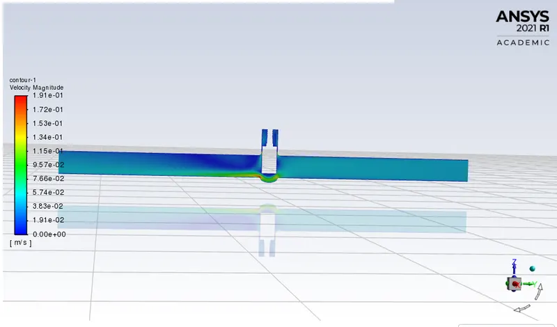
Velocity counter:
 c
c
CASE 4:
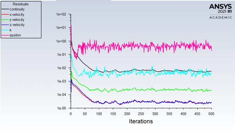
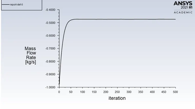
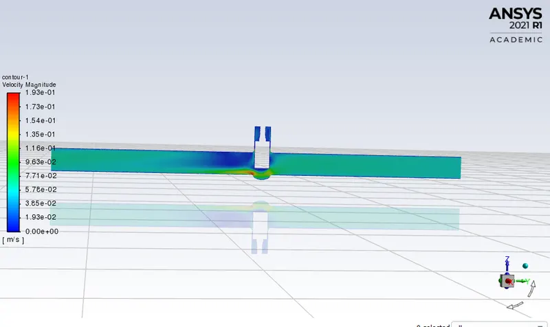
We have lifted the gate valve: 0.04.
Part 1:
|
SETUP |
||
|
Gravity |
-9.81 in the Z direction | |
|
Solver Type |
Pressure-Based |
|
|
Velocity Formulation |
Absolute |
|
|
Time |
|
|
|
Models |
Viscous model: K-epsilon, Realize, Scaled wall functions. Energy model: OFF |
|
|
Material |
Fluid type: Water Solid-type: Aluminium |
|
|
Cell zones |
Fluid type: water Solid: Al |
|
|
Boundaries |
Pressure Inlet: 10pa Wall:- wall Outlet:-Outlet pressure Volume: interior |
|
|
Reference values |
Standard |
|
|
Definitions |
Mass flow rate | |
|
Initialization |
Standard Starting from inlet |
Residual plot:
Mass flow rate:
Velocity counter:
CASE 5:
We have lifted the gate valve: 0.05.
Part 1:
|
SETUP |
||
|
Gravity |
-9.81 in the Z direction | |
|
Solver Type |
Pressure-Based |
|
|
Velocity Formulation |
Absolute |
|
|
Time |
|
|
|
Models |
Viscous model: K-epsilon, Realize, Scaled wall functions. Energy model: OFF |
|
|
Material |
Fluid type: Water Solid-type: Aluminium |
|
|
Cell zones |
Fluid type: water Solid: Al |
|
|
Boundaries |
Pressure Inlet: 10pa Wall:- wall Outlet:-Outlet pressure Volume: interior |
|
|
Reference values |
Standard |
|
|
Definitions |
Mass flow rate | |
|
Initialization |
Standard Starting from inlet |
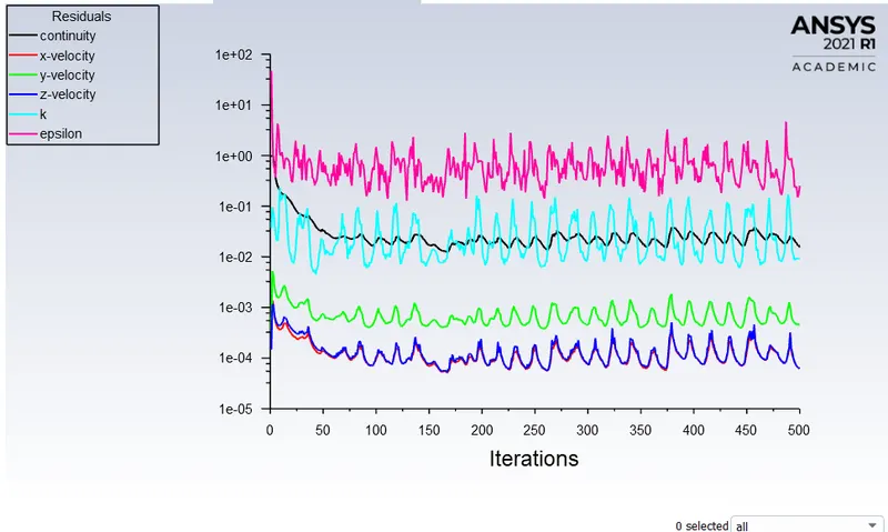
Residual plot:
Mass flow rate:
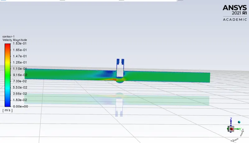
Velocity counter:
CASE 6:
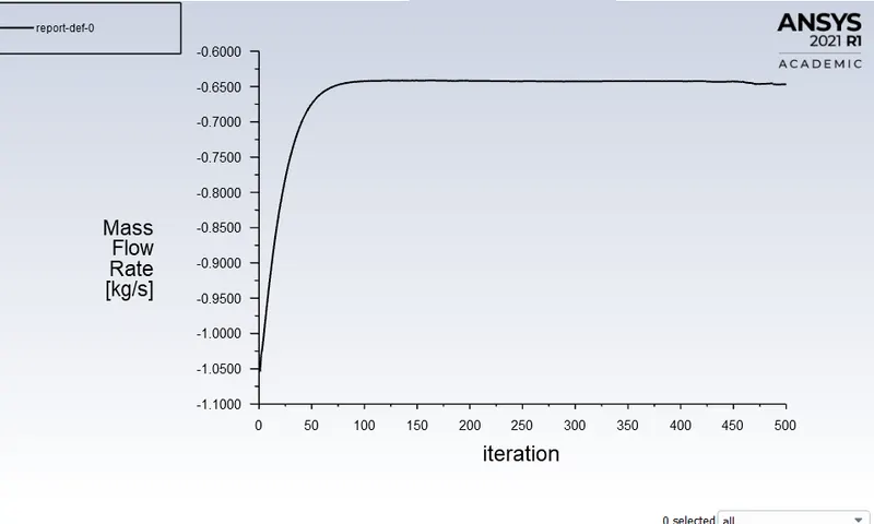
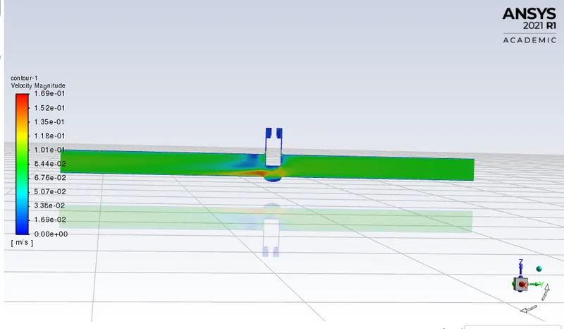
We have lifted the gate valve: 0.06.
Part 1:
|
SETUP |
||
|
Gravity |
-9.81 in the Z direction | |
|
Solver Type |
Pressure-Based |
|
|
Velocity Formulation |
Absolute |
|
|
Time |
|
|
|
Models |
Viscous model: K-epsilon, Realize, Scaled wall functions. Energy model: OFF |
|
|
Material |
Fluid type: Water Solid-type: Aluminium |
|
|
Cell zones |
Fluid type: water Solid: Al |
|
|
Boundaries |
Pressure Inlet: 10pa Wall:- wall Outlet:-Outlet pressure Volume: interior |
|
|
Reference values |
Standard |
|
|
Definitions |
Mass flow rate | |
|
Initialization |
Standard Starting from inlet |
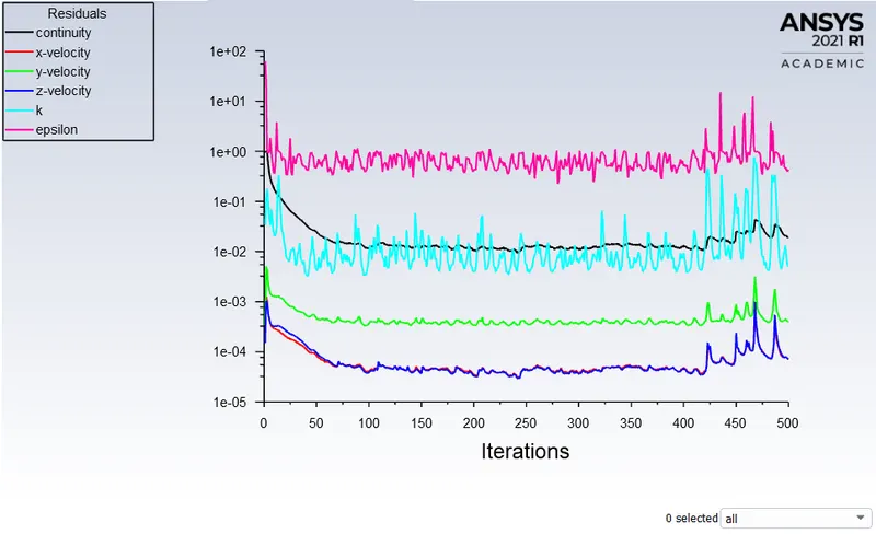
Residual plot:
Mass flow rate:
Velocity counter:
CASE 7:
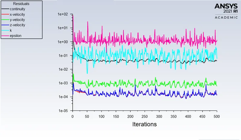
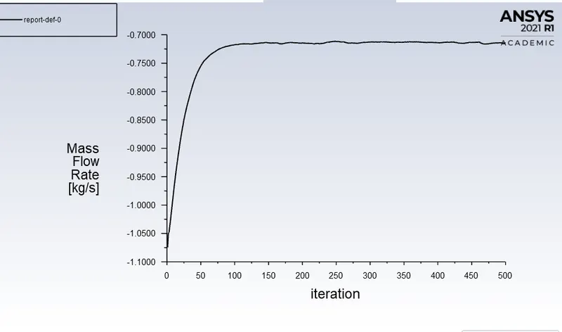
We have lifted the gate valve: 0.07.
Part 1:
|
SETUP |
||
|
Gravity |
-9.81 in the Z direction | |
|
Solver Type |
Pressure-Based |
|
|
Velocity Formulation |
Absolute |
|
|
Time |
|
|
|
Models |
Viscous model: K-epsilon, Realize, Scaled wall functions. Energy model: OFF |
|
|
Material |
Fluid type: Water Solid-type: Aluminium |
|
|
Cell zones |
Fluid type: water Solid: Al |
|
|
Boundaries |
Pressure Inlet: 10pa Wall:- wall Outlet:-Outlet pressure Volume: interior |
|
|
Reference values |
Standard |
|
|
Definitions |
Mass flow rate | |
|
Initialization |
Standard Starting from inlet |
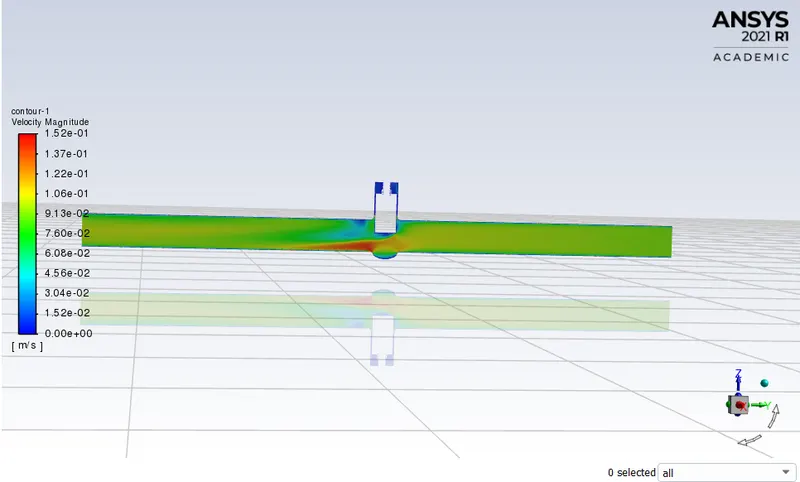
Residual plot:
Mass flow rate:
Velocity counter:
CASE 8:
We have lifted the gate valve: 0.08.
Part 1:
|
SETUP |
||
|
Gravity |
-9.81 in the Z direction | |
|
Solver Type |
Pressure-Based |
|
|
Velocity Formulation |
Absolute |
|
|
Time |
|
|
|
Models |
Viscous model: K-epsilon, Realize, Scaled wall functions. Energy model: OFF |
|
|
Material |
Fluid type: Water Solid-type: Aluminium |
|
|
Cell zones |
Fluid type: water Solid: Al |
|
|
Boundaries |
Pressure Inlet: 10pa Wall:- wall Outlet:-Outlet pressure Volume: interior |
|
|
Reference values |
Standard |
|
|
Definitions |
Mass flow rate | |
|
Initialization |
Standard Starting from inlet |
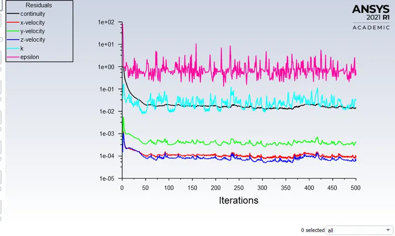
Residual plot:
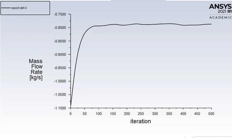
Mass flow rate:
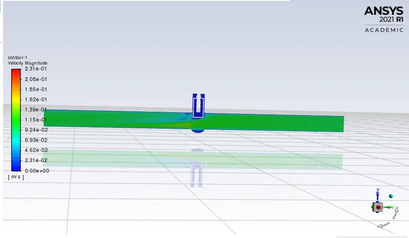
Velocity counter:
Parametric Table of mass flow rate:
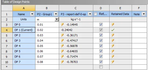
Using the following formulas
To calculate the Flow coefficient
`k_v=Q((SG)/(DeltaP))^0.5`
`c_v=1.1560*k_v`
Final Table:
| Case 1 | Lift of gate valve | The mass flow rate in Kg/s | Flow Coefficient | Flow Factor |
| 1 | 0.01 | -0.14945 | 0.004726 | 0.004087 |
| 2 | 0.02 | -0.24042 | 0.075807 | 0.065573 |
| 3 | 0.03 | -0.36171 | 0.011438 | 0.009893 |
| 4 | 0.04 | -0.47417 | 0.149945 | 0.129702 |
| 5 | 0.05 | -0.56878 | 0.179864 | 0.155582 |
| 6 | 0.06 | -0.64655 | 0.204457 | 0.176855 |
| 7 | 0.07 | -0.71474 | 0.226020 | 0.195507 |
| 8 | 0.08 | -0.78704 | 0.248880 | 0.215812 |
Conclusion:
1. Mass flow rate gradually increses as the lift of gate disc is increased.
2. The variation of flow coefficient and flow factor with the opening of the valve is studied by using parametric.
3. Parametric study is time reducing option when studying the effects of changes of certain parameters on a system.
4. Flow coefficient plays important role in the selection of valve and sizing of a valve, so calculating it is necessary.
5. flow coefficient also helps in computing the efficiency of the system and the effect of pressure on the system.