Week 9 - Parametric study on Gate valve.
A PARAMETRIC STUDY ON GATE VALVE
A gate valve, also known as a sluice valve, is a valve that opens by lifting a barrier (gate) out of the path of the fluid. Gate valves require very little space along the pipe axis and hardly restrict the flow of fluid when the gate is fully opened. The gate faces can be parallel but are most commonly wedge-shaped (in order to be able to apply pressure on the sealing surface)
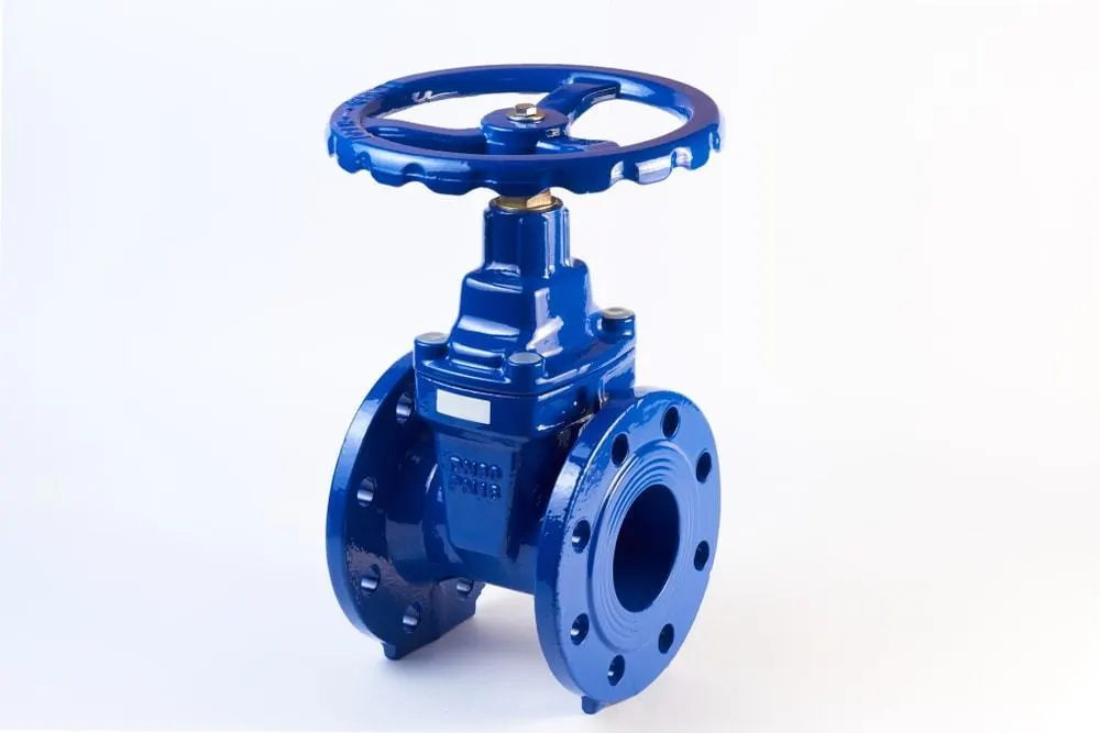
Gate valves are used to shut off the flow of liquids rather than for flow regulation. When fully open, the typical gate valve has no obstruction in the flow path, resulting in very low flow resistance.[1] The size of the open flow path generally varies in a nonlinear manner as the gate is moved. This means that the flow rate does not change evenly with stem travel. Depending on the construction, a partially open gate can vibrate from the fluid flow.
Gate valves are mostly used with larger pipe diameters (from 2" to the largest pipelines) since they are less complex to construct than other types of valves in large sizes.
At high pressures, friction can become a problem. As the gate is pushed against its guiding rail by the pressure of the medium, it becomes harder to operate the valve. Large gate valves are sometimes fitted with a bypass controlled by a smaller valve to be able to reduce the pressure before operating the gate valve itself.
Gate valves without an extra sealing ring on the gate or the seat are used in applications where minor leaking of the valve is not an issue, such as heating circuits or sewer pipes.
Common gate valves are actuated by a threaded stem that connects the actuator (e.g. handwheel or motor) to the gate. They are characterised as having either a rising or a nonrising stem, depending on which end of the stem is threaded. Rising stems are fixed to the gate and rise and lower together as the valve is operated, providing a visual indication of valve position. The actuator is attached to a nut that is rotated around the threaded stem to move it. Nonrising stem valves are fixed to, and rotate with, the actuator, and are threaded into the gate. They may have a pointer threaded onto the stem to indicate valve position, since the gate's motion is concealed inside the valve. Nonrising stems are used where vertical space is limited.
Gate valves may have flanged ends drilled according to pipeline-compatible flange dimensional standards.
Gate valves are typically constructed from cast iron, cast carbon steel, ductile iron, gunmetal, stainless steel, alloy steels, and forged steels.
All-metal gate valves are used in ultra-high vacuum chambers to isolate regions of the chamber.[2]
Bonnet
Bonnets provide leakproof closure for the valve body. Gate valves may have a screw-in, union, or bolted bonnet. A screw-in bonnet is the simplest, offering a durable, pressure-tight seal. A union bonnet is suitable for applications requiring frequent inspection and cleaning. It also gives the body added strength. A bolted bonnet is used for larger valves and higher pressure applications.
Pressure seal bonnet
Another type of bonnet construction in a gate valve is pressure seal bonnet. This construction is adopted for valves for high pressure service, typically in excess of 2250 psi (15 MPa). The unique feature of the pressure seal bonnet is that the bonnet ends in a downward-facing cup that fits inside the body of the valve. As the internal pressure in the valve increases, the sides of the cup are forced outward. improving the body-bonnet seal. Other constructions where the seal is provided by external clamping pressure tend to create leaks in the body-bonnet joint.
Knife gate valve
For plastic solids and high-viscosity slurries such as paper pulp, a specialty valve known as a knife gate valve is used to cut through the material to stop the flow. A knife gate valve is usually not wedge shaped and has a tapered knife-like edge on its lower surface
Types of Gate Valves
There are three ways to classify the gate valve.
- Types of Disk
- Solid taper wedge
- Flexible wedge
- Split wedge or Parallel disks Valve
- Types of Body Bonnet Joint
- Screwed Bonnet
- Bolted-Bonnet
- Welded-Bonnet
- Pressure-Seal Bonnet
- Types of Stem movement
- Rising Stem or OS & Y Type (Outside Stem and Screw Type)
- Non-rising Stem type
Simulation
Here we have a Gate valve with which we are simulating flow of (fluid) through it ad how the level of the gate affects the velocity and pressure throughout the volume medium.
Geometry
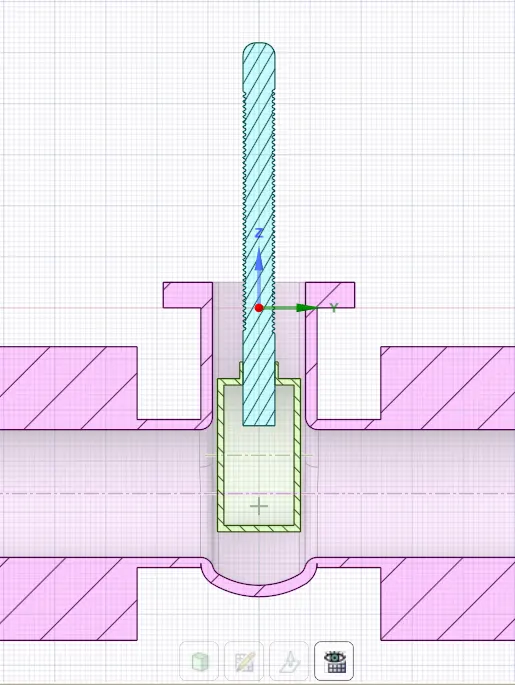
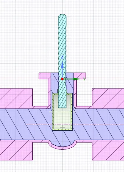
Below you can see the part imported Space claim. In space claim we prepare the geometry and extract the fluid volume because we are dealing with water.
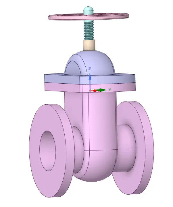
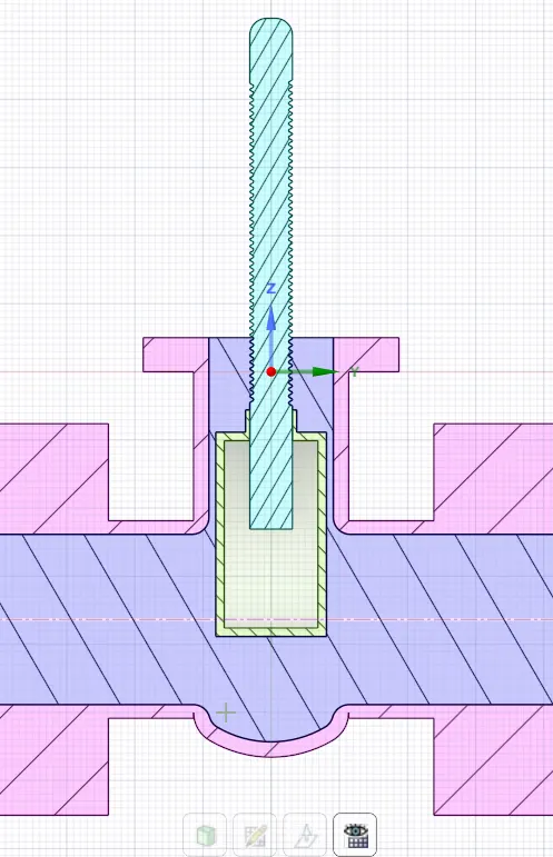
When you hide the bottom part of the gate valve we get to see the gate disk.
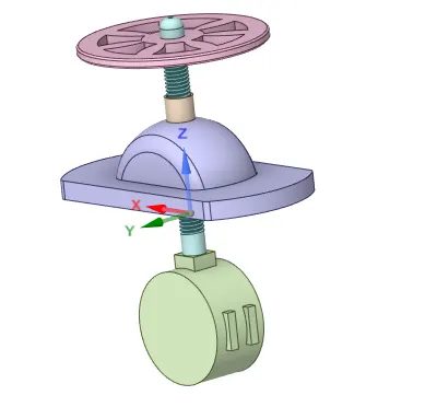
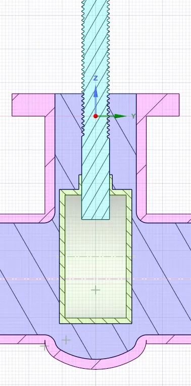
The above picture shows the mechanism of the gate valve, the Green color gate disk moves up and down in the enclosed space letting fluid out. The level of the gate disk can be controlled by the spindle which is connected to the hand wheel on the top. When we turn the hand wheel the gate disk moves up or down opening or closing the passage of fluid.
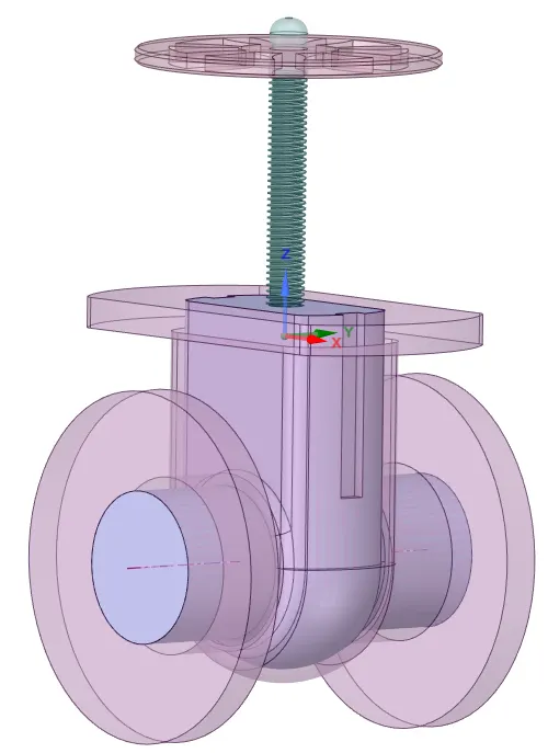
We extract the fluid volume from the geometry and extend the volume for ease. You can see the extended volume in the mesh profile. We need to be careful while extracting the fluid volume and confirm that your domain deals with the extracted volume only.
Meshing

Above image is the mesh profile. The base mesh didnt seem to give the accuracy i wanted visually.The no of nodes and elements is given in the snippet below.
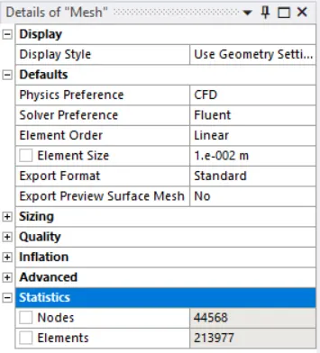 Since the 500,000 elements mark isnt crossed this simulation can be done without having any license problem
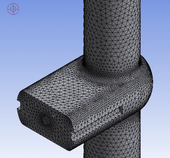
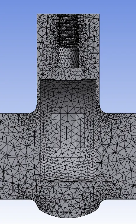 As you can see here the mesh is fine.
setup details
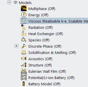
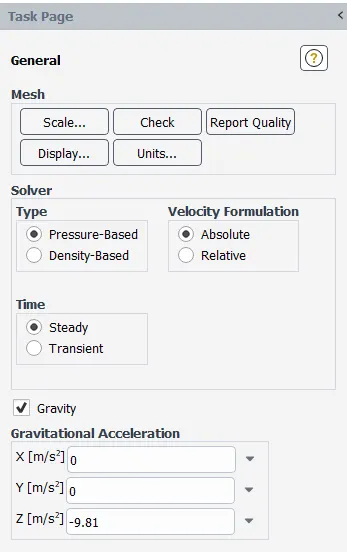
If you look at the above snippets you can see tha i have Enabled gravity in the negative z-axis, this is because of the orientation of the geometry.
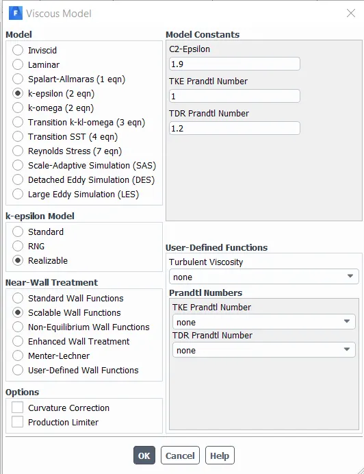
For the viscous model i hhave opted for the K-epsilon(Realizable) model with scalable wall functions
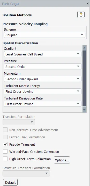 Here are the Methods usd by ANSYS to solve the problem and attain the correct solution.
Below you can find the details on the boundary conditions. The inlet and outlet are pressure dependant and not velocity. A pressure of 10 pascals is applied at the inlet with 0 guage pressure at the outlet.
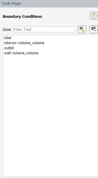
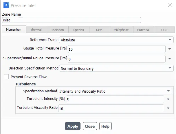
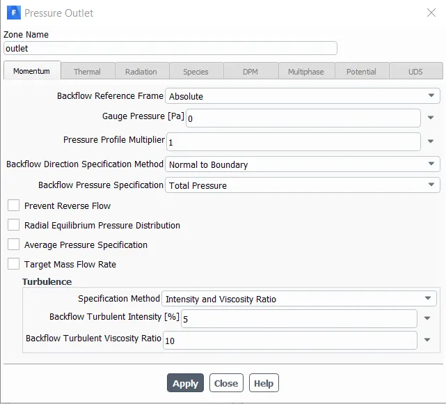
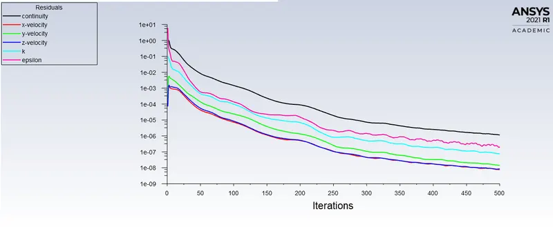
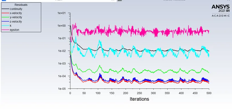
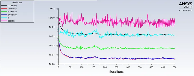
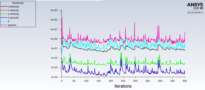
With these settings and contour plot applied, this simulation was run for 500 iterations with scaling factor 1.
Results
There are 4 cases of lift
1. 30mm
2. 40mm
3. 45mm
4. 50mm
1. 20mm lift results
Mass flow rate = -0.2370556 kg/s
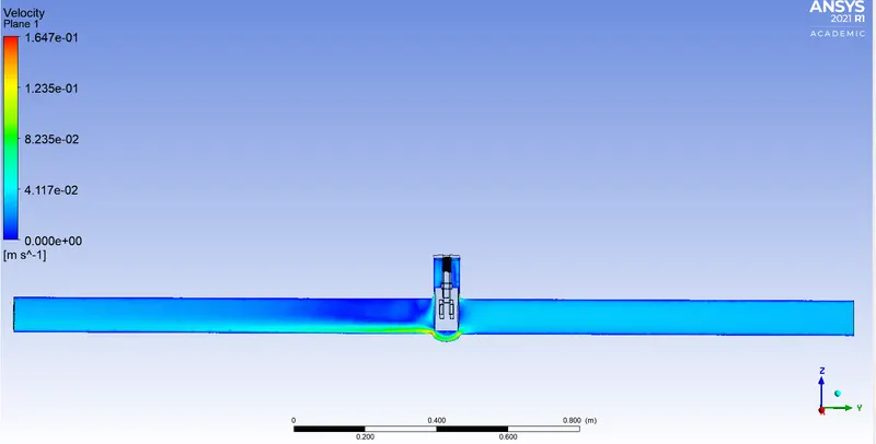
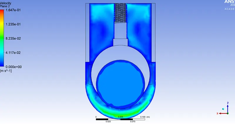
2. 30mm lift results
Mass flow rate = -0.3579211 kg/s
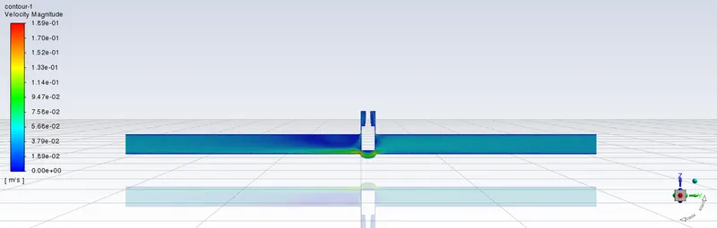
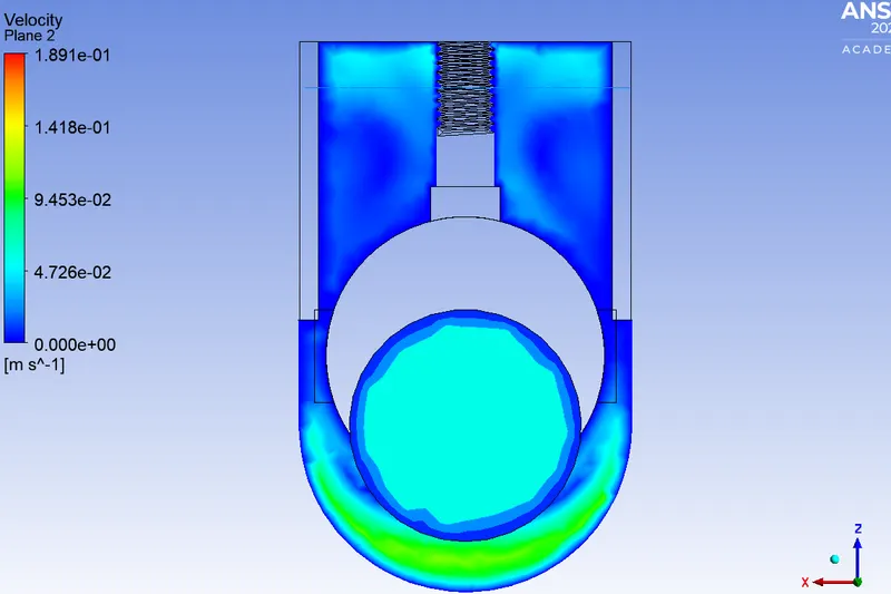
3. 40mm lift results
Mass flow rate = -0.4625 kg/s
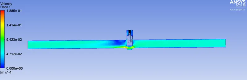
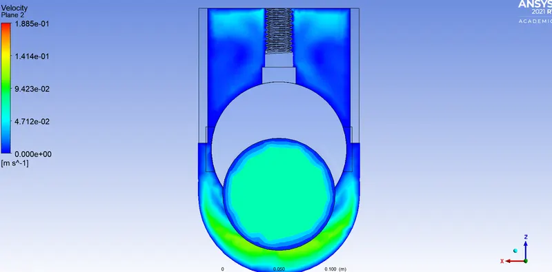
4. 50mm lift results
Mass flow rate = -0.55615487
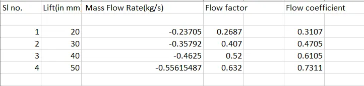
Below you can find the table with all the results
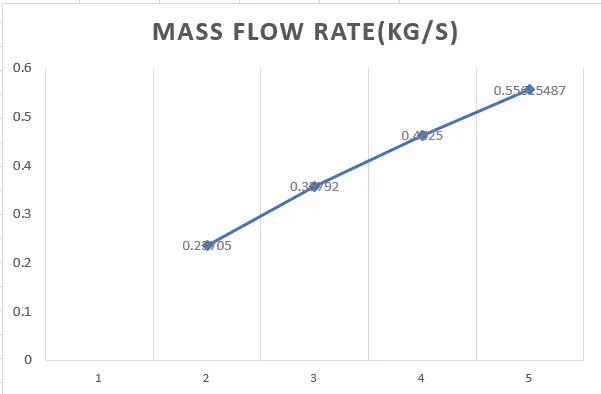
Sl no ----->
The flow coefficient of a device is a relative measure of its efficiency at allowing fluid flow. It describes the relationship between the pressure drop across an orifice valve or other assembly and the corresponding flow rate.
Mathematically the flow coefficient Cv (or flow-capacity rating of valve) can be expressed as :

where:
- Q is the rate of flow (expressed in US gallons per minute),
- SG is the specific gravity of the fluid (for water = 1),
- ΔP is the pressure drop across the valve (expressed in psi).
The metric equivalent flow factor (Kv; commonly used everywhere else in the world with the exception of the United States) is calculated using metric units :

where
- Kv is the flow factor (expressed in
 ).
). - Q is the flowrate (expressed in cubic metres per hour

- SG is the specific gravity of the fluid (for water = 1),
- ∆P is the differential pressure across the device (expressed in [bar]).
Kv can be calculated from Cv using the equation:
 (This is the equation i used to get the Flow coefficient Cv)
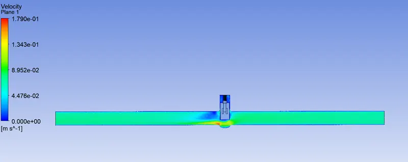
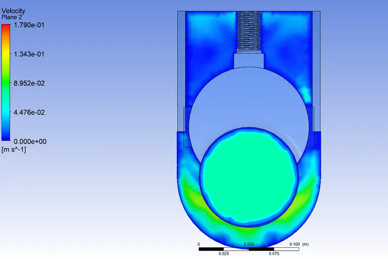
Now looking at the Table above we can observe that with the increase in the lift the fluid(Water) flow rate is higher as should be the case in reality. As you open a gate valve further it lifts even higher to give the maximum flow. Here with the contour plots above we can also see where the velocity is at it highest. It is highest where there is a change in volume from a large volume to small volume and then large volume again which creates a nozzle effect which causes the water to flow faster at the region of high volume to low volume transition.