Week 9 - Parametric study on Gate valve.
Introduction
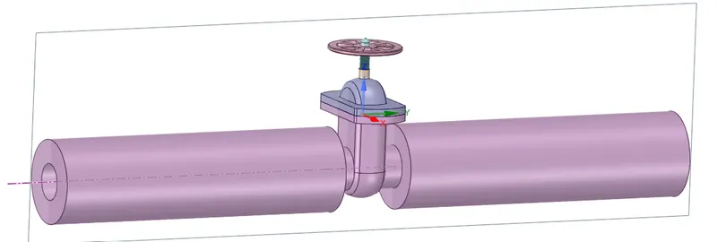
A Gate valve ( mostly used for large diameters ) is a valve that opens by lifting a barrier (gate) out of the path of the fluid. Gate valves require very little space along the pipe axis and hardly restrict the flow of fluid when the gate is fully opened. Therefore a fully opened valve does not obstruct the path of fluid flow. Although it can be used to shut off the flow and regulate the flow, it is mainly used to stop fluid flow. Depending on the construction, a partially open gate can vibrate from the fluid flow. At high pressures, friction can become a problem and makes it harder to operate the valve. Following is a stainless steel gate valve with flanged ends. Bolts connect the lower valve body with the upper “bonnet”. This is a raising-stem valve.
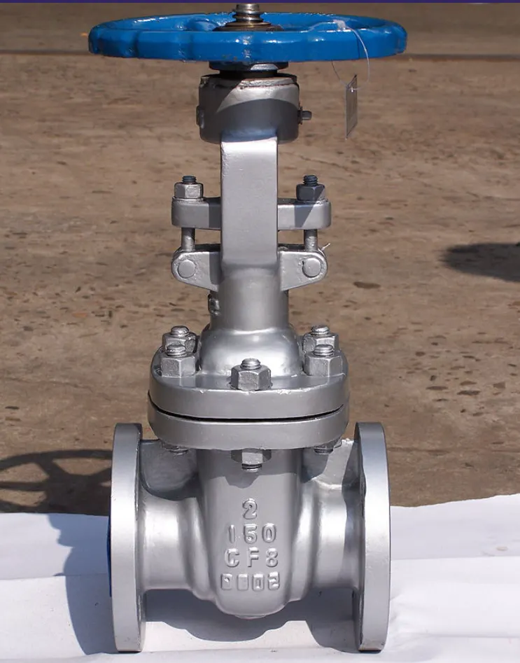
Computational Model (Spaceclaim)
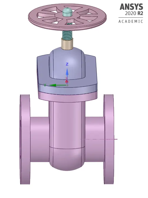
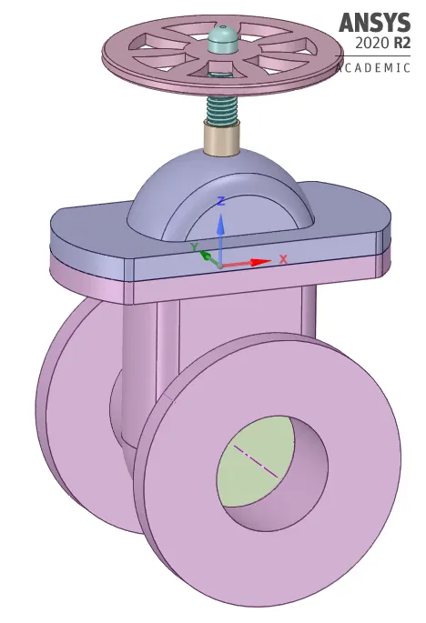
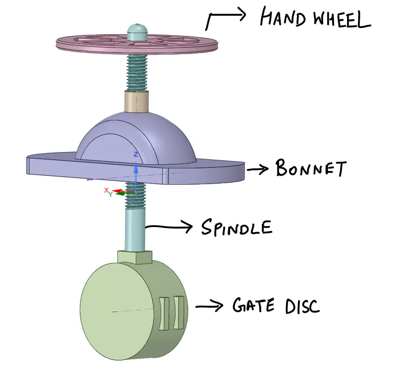
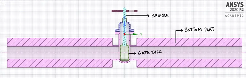
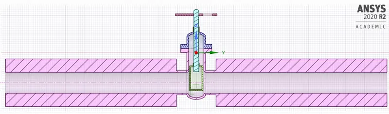
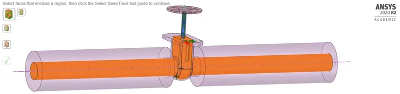
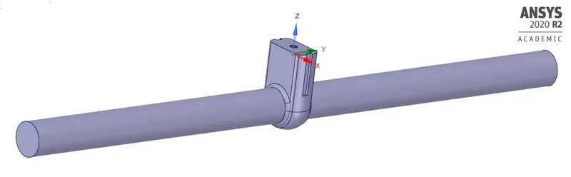
The above is the model analysed in Ansys fluent. It has the main features of a gate valve. The components of the gate valve are the Handwheel, Spindle, Bonnet, Gate Disc, Bottom part. Initially, the valve is fully closed. We have to increase the lift of the gate disc for every design point of the parametric study. We use the parameter option to parametrize the lift of the Gate Disc. The lift is given by using the "move" command in Ansys Spaceclaim, after that we extract the fluid volume. We use the "pull" command to create the pipe geometry.
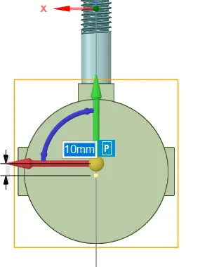
Initial Gate Disc position (fully closed)
Gate Disc position (Partially open)
Fluid Volume Extraction
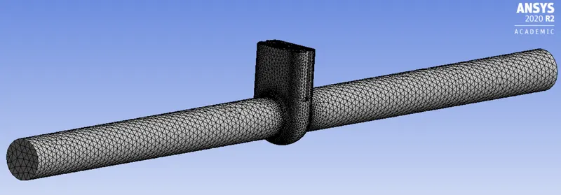
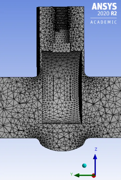
Computational Mesh
We use the default computational mesh. Element size = 92.892 mm.
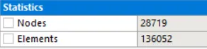
Sectional View

Element Quality
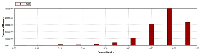
--> Mesh size and Mesh parameters will vary with respect to lift of gate disc but it will not make much of a difference. Following is the table of the Parametric study with the design points and lift of the gate disc.
| Design Point | Lift [mm] |
| dp0 | 10 |
| dp1 | 20 |
| dp2 | 33 |
| dp3 | 40 |
| dp4 | 50 |
Fluid Flow Setup
We are using Gravity enabled steady-state Simulation. The realizable k-e turbulence model is used with scalable wall functions. The fluid used is water.
density rho = 998.2 kg/m3
Dynamic Viscosity mu = 0.001003 kg/m-s
Inlet face is assigned pressure-inlet boundary condition with an inlet pressure of 10 Pa. The outlet is assigned with pressure outlet boundary condition. Rest faces are no-slip wall boundary condition. A report plot is created for the mass flow rate. The solution is initialized with standard initialization with values computed at the inlet face.
Results
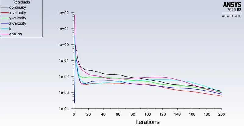
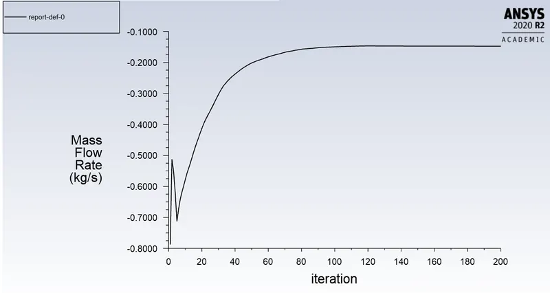
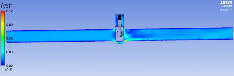
Design Point 0 - Gate valve Lift = 10 mm.
Residual plot
Mass-flow-rate

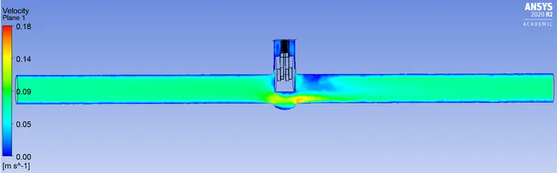
Velocity contour
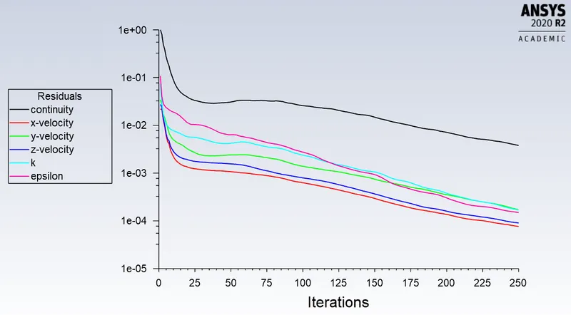
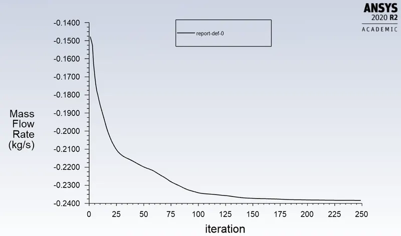
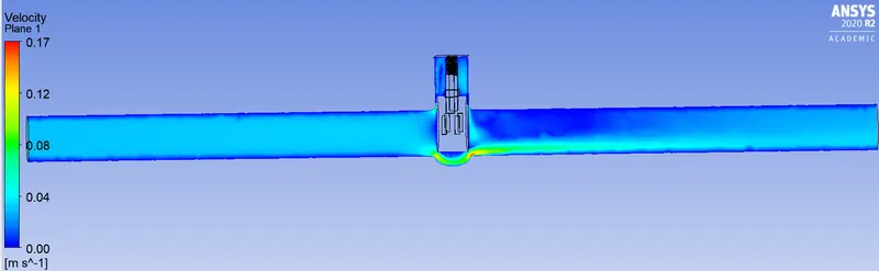
Design Point 1 - Gate valve Lift = 20 mm.
Residual plot
Mass-flow-rate

Velocity contour
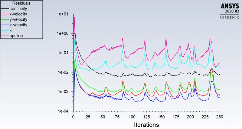
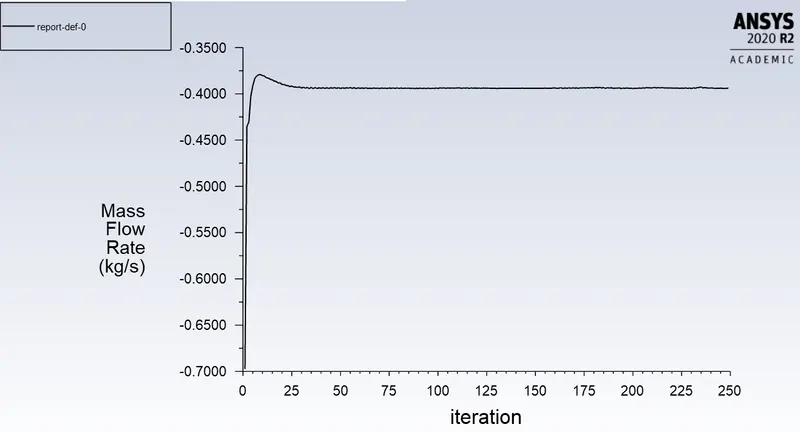
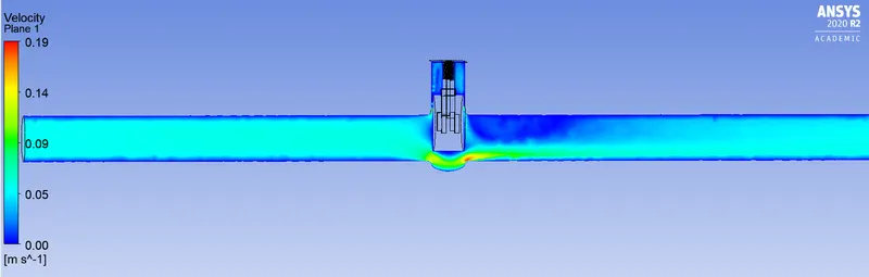
Design Point 2 - Gate valve Lift = 33 mm.
Residual plot
Mass-flow-rate

Velocity contour
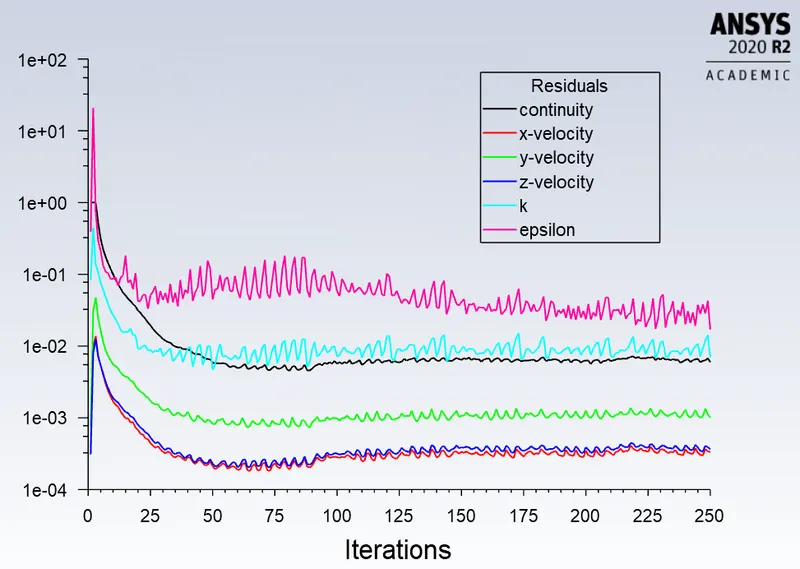
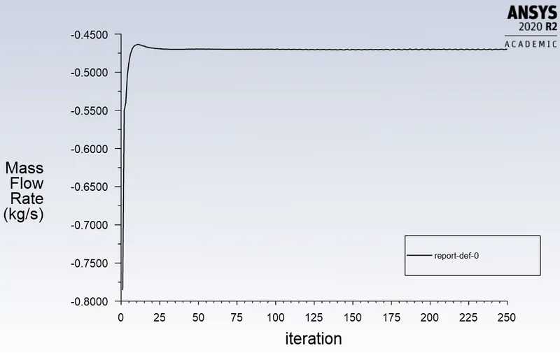
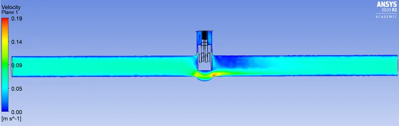
Design Point 3 - Gate valve Lift = 40 mm.
Residual plot
Mass-flow-rate

Velocity contour
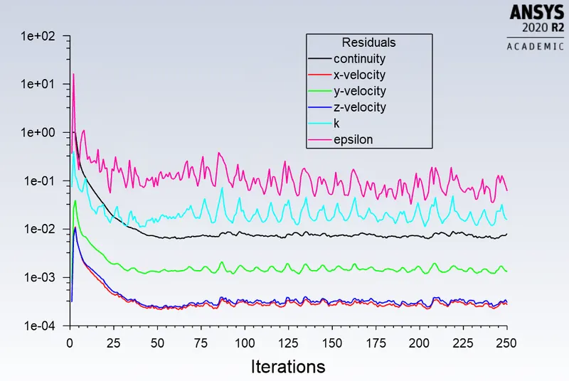
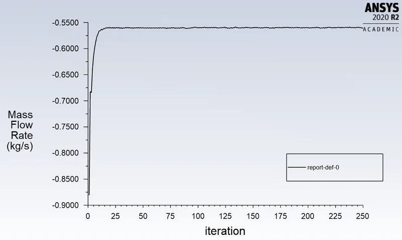
Design Point 4 - Gate valve Lift = 50 mm.
Residual plot
Mass-flow-rate

Velocity contour
Conclusion
| Design Point | Lift [mm] | Mass Flow Rate [kg/s] |
| dp0 | 10 | -0.14775625 |
| dp1 | 20 | -0.23832169 |
| dp2 | 33 | -0.39452034 |
| dp3 | 40 | -0.46984304 |
| dp4 | 50 | -0.56045021 |
--> Parametric Study was done using Ansys fluent on the Gate valve.
--> Lift of the gate disc was parameterized and corresponding mass flow rate computed.